Table of Contents
Advertisement
INSTALLATION MANUAL
STG - ROTISSERIE OVEN MODELS
STW - WARMER MODELS
MODELS
STG5 P
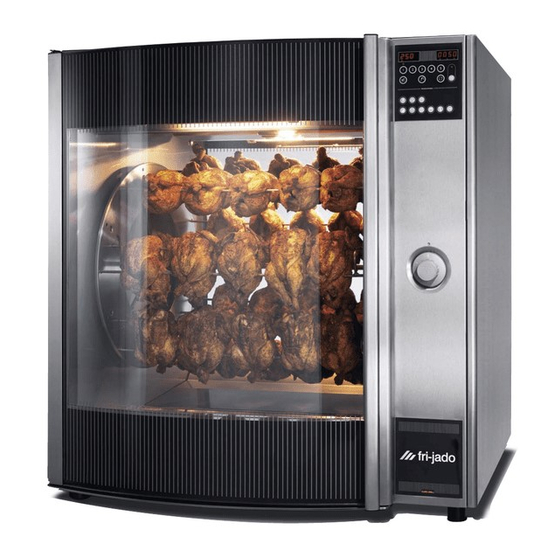
STG7 P
STW5
STW7
This manual is prepared for the use of trained Service Technicians and
should not be used by those not properly qualified. If you have atten-
ded a trianing for this product, you may be qualified to perform all the
This manual is not intended to be all encompassing. If you have not at-
tended a training for this product, you should read, in its entirety, the
repair procedure you wish to performto determine if you have the ne-
cessary tools, instruments and skills required to perform the procedure.
Procedures for which you do not have the necessary tools, instruments
Reproduction or other use of this Manual, without the express written
WWW.FRIJADO.COM
Model STG7 P
- NOTICE -
procedures in this manual.
and skills should be performed by a trained technician.
consent of Fri-Jado, is prohibited.
Model STW7
Installation Manual STG5/7 STW5/7 form 9123656 rev. 03/2010
Advertisement
Table of Contents

Related Manuals for Fri-Jado STG5 P


Summary of Contents for Fri-Jado STG5 P
- Page 1 Procedures for which you do not have the necessary tools, instruments and skills should be performed by a trained technician. Reproduction or other use of this Manual, without the express written consent of Fri-Jado, is prohibited. WWW.FRIJADO.COM Installation Manual STG5/7 STW5/7 form 9123656 rev. 03/2010...
- Page 2 Installation Manual STG5/7 STW5/7 form 9123656 rev. 03/2010 Page 2...
-
Page 3: Table Of Contents
TABLE OF CONTENTS Index Index ................................3 General technical data ..........................4 Technical data ............................4 Installation procedures ..........................5 Unpacking the unit ..........................5 Location ..............................6 Electrical supply ............................. 6 Legs / Castors ............................7 Tethering of the unit ..........................7 Test run .............................. -
Page 4: General Technical Data
GENERAL TECHNICAL DATA GENERAL TECHNICAL DATA The STG and STW rotisserie ovens and warmers feature full view tempered glass doors, both front and back, and quartz lighting that promotes visual appeal and stimulates customer interest. All of the information, illustrations and specifications contained in this manual are based on the latest product information available at the time of printing. -
Page 5: Installation Procedures
INSTALLATION PROCEDURES INSTALLATION PROCEDURES • Unpacking of the unit. • Remove the pallet under the unit with the help of a fork lift. • Put the unit on his location. • Check if there is enough free space around the unit (see installation drawing). • Check the electrical supply. • Tethering of the unit • STG: Load a program in the memory and make a test run on 250°C. • STW: Make a test run on 100°C. • Give instructions to the operator. UNPAckING ThE UNIT Immediately after unpacking the oven, check for possible shipping damage. If the oven is found to be damaged, save the packaging material and contact the carrier within 15 days of delivery. -
Page 6: Location
INSTALLATION PROCEDURES LOcATION The oven must be installed on a level surface. The installation location must allow adequate clearances for servicing and proper operation. IMPORTANT: Make sure you lea- ve sufficient space around the rotisserie or warmer to easily remove or insert the rotor. If the base has (rotating) wheels, the floor on which it rests must be level. -
Page 7: Legs / Castors
INSTALLATION PROCEDURES LEGS / cASTORS Each oven and warmer is furnished on 40mm legs. Stacked models are furnished with 2 swi- vel and 2 locking swivel castors. A castor-equipped stand with convenient storage drawer is available; the oven is mounted on top of the stand. TEThERING Of ThE UNIT (For model STG 5 and STG 7 units when stacked or placed on base with castors) Warning: Safety standards require that, when this appliance is properly connected to the... -
Page 8: Test Run
INSTALLATION PROCEDURES TEST RUN The oven must be burned in to release any odours that might result from heating the new oven surfaces. Operate the oven at maximum temperature setting of 250°C for 30 minutes and the warmer on 100°C. Smoke with an unplaesant odour will normally be given off du- ring this burn-in period. ExTRAcTION Of ThE ROTISSERIE Although an extraction hood is not prescribed, it could be desired that a hood is placed over the rotisserie. -
Page 9: Placing And Connecting Of The Units
PLACING AND CONNECTING PLACING AND CONNECTING OF THE UNITS Description belonging to the lables on the drawings Label Description Power cable, length 2,2 meters * Exhaust opening Space between a rotisserie and a wall or ceiling Location for socket *) length is measured from the point where the cables coms out of the unit STG 5 Installation Manual STG5/7 STW5/7 form 9123656 rev. - Page 10 PLACING AND CONNECTING STG 7 1025 Installation Manual STG5/7 STW5/7 form 9123656 rev. 03/2010 Page 10...
-
Page 11: Stg 5 + 5
PLACING AND CONNECTING STG 5 + 5 Installation Manual STG5/7 STW5/7 form 9123656 rev. 03/2010 Page 11... -
Page 12: Stg 7 + 7
PLACING AND CONNECTING STG 7 + 7 Installation Manual STG5/7 STW5/7 form 9123656 rev. 03/2010 Page 12... -
Page 13: Stg 5 + Stw 5
PLACING AND CONNECTING STG 5 + STW 5 Installation Manual STG5/7 STW5/7 form 9123656 rev. 03/2010 Page 13... -
Page 14: Stg 7 + Stw 7
PLACING AND CONNECTING STG 7 + STW 7 Installation Manual STG5/7 STW5/7 form 9123656 rev. 03/2010 Page 14... -
Page 15: Stg 5 On Base
PLACING AND CONNECTING STG 5 ON bASE Installation Manual STG5/7 STW5/7 form 9123656 rev. 03/2010 Page 15... -
Page 16: Stg 7 On Base
PLACING AND CONNECTING STG 7 ON bASE Installation Manual STG5/7 STW5/7 form 9123656 rev. 03/2010 Page 16... -
Page 17: Stw 5
PLACING AND CONNECTING STW 5 Installation Manual STG5/7 STW5/7 form 9123656 rev. 03/2010 Page 17... -
Page 18: Stw 7
PLACING AND CONNECTING STW 7 1025 Installation Manual STG5/7 STW5/7 form 9123656 rev. 03/2010 Page 18... -
Page 19: Stw 5 On Base
PLACING AND CONNECTING STW 5 ON bASE Installation Manual STG5/7 STW5/7 form 9123656 rev. 03/2010 Page 19... -
Page 20: Stw 7 On Base
PLACING AND CONNECTING STW 7 ON bASE Installation Manual STG5/7 STW5/7 form 9123656 rev. 03/2010 Page 20... - Page 21 Page 21 Installation Manual STG5/7 STW5/7 form 9123656 rev. 03/2010...
- Page 22 Fri-Jado B.V. • P.O. Box 560 • 4870 AN • Etten-Leur • The Netherlands • tel +31 76 50 85 400 • fax +31 76 50 85 444 • info@frijado.com • www.frijado.com...
Need help?
Do you have a question about the STG5 P and is the answer not in the manual?
Questions and answers