Advertisement
Quick Links
Advertisement

Related Manuals for Storage Canopy DT Container shelter


Summary of Contents for Storage Canopy DT Container shelter
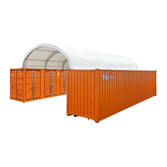
- Page 1 SHELTER ASSEMBLY MANUAL 40x80x15 DT Container shelter Double Truss...
-
Page 2: Parts List
PARTS LIST Part Code Description Top bent tube Side bent tube Lower bent tube Purlin Top tensioning device Clips Left base plate Right base plate Ratchet Nylon band for ratchet Tensioning tube 2 groups Bolts M8x70 Bolts M12x30 Bolts M10x80 Roof cover Knitting rope for cover Plastc plug... - Page 3 ANCHORING THE CONTAINER Make sure you have: • Welder. • Cement. • Four 3” x 3” x 6 feet ¼” Square steel angle 1. As shown in the diagram 1, make a 3 ft deep hole right beside one of the front and opposite rear corners of the container, in which the 6ft square steel will be installed.
- Page 4 Highly Recommended 1. All container canopy covers need to be removed during windstorm of 60 mph, leaving frame assembled. Customer responsibility. 2. All container canopy covers need to be removed before a snowstorm of 1-2 inches (for single truss Shipping container roofs) and 3-4 inches (for double truss Shipping container roofs), leaving the frame assembled.
-
Page 5: Specifications
SPECIFICATIONS Width: 40 ft Length: 80 ft Height: 15 ft IMPORTANT: READ MANUAL FIRST Improper site preparation, assembly and maintenance may invalidate warranty and cause unnecessary and costly mistakes. If you have any questions, contact your local dealer. For an easy assembly process, we have identified each individual component with the part code as indicated in the parts list. -
Page 6: Installation Process
EQUIPMENT AND TOOLS FOR INSTALLATION 1. Measuring tape 2. Alignment string 3. Step ladder 4. Welder 5. Sledgehammer 6. Wrench 7. Scissors INSTALLATION PROCESS A - BASE PLATES INSTALLATION Please refer to the Figure 1 to place the base plates. Figure 1 1. - Page 7 B - FRAME INSTALLATION (Refer to figure 2 for the full diagram) Figure 2 1. Connect the Top Bent Tube (part code 1), the Side Bent Tube (part code 2) and the Lower Bent Tube (part code 3) with the Bolts M8x70 (part code 11); these make one group of arches.
- Page 8 2. Insert one end of the assembled arch into one base plate and force the other end of the arch into the opposite base plate. Figure 4 3. After installing the first two arches, connect the Purlin (part code 4) onto them using the Bolts M10x80 (part code 12).
- Page 9 C - ROOF COVER INSTALLATION NOTE: DO NOT install the cover onto the frame of your building in high wind conditions. A slight breeze is the most advantageous for cover installation. To take advantage of the breeze, pull the cover up over the arches with the breeze blowing in the cover like a sail filled with air.
- Page 10 3. On the Roof cover, cut pockets over each ratchet on the base plates, then use the Nylon band for ratchet (part code 9) to tie down the Tensioning tubes. Figure 8 4. Weld the Angle seats (part code 16) on each container and use Knitting Rope for Cover (part code 14) to knit the cover on the two side arches and tie the Knitting Rope for Cover to the Angle seats.
- Page 11 Please, check the detailed installation pictures below: NOTES: DO NOT LEAVE THE ROOF COVER UNATTACHED UNDER ANYCIRCUMSTANCES until the final assembly and tightening has been completed. The process is quite easy, but some tightening adjustments will be necessary to get a flat, tensioned roof cover.
Need help?
Do you have a question about the DT Container shelter and is the answer not in the manual?
Questions and answers