Advertisement
Quick Links
Advertisement

Related Manuals for Storage Canopy Two Car Garage Shelter


Summary of Contents for Storage Canopy Two Car Garage Shelter
- Page 1 SHELTER ASSEMBLY MANUAL Two Car Garage Shelter...
- Page 2 Parst List Roof bent tube Incline tube Shoulder bent tube Standing leg Purlin Supporting tube for roof frame Base Plate Base Plate at middle Ratchet Tension tube Stake peg Roof cover Front and back cover bolt 8*70mm bolt 10*80mm bolt 8*20mm Rope 60 m Nylon Band for Ratchet...
-
Page 3: Specification
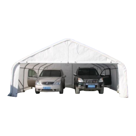
SPECIFICATION Width:22 Length: 24 Height: 11 ft IMPORTANT ---- READ MANUAL FIRST Improper site preparation, Assembly and Maintenance may invalidate warranty and cause unnecessary and costly mistake. If you have any questions contact your local dealer. For user friendly assembly we have identified each individual component with the part code as indicated in the parts list. -
Page 4: Installation Process
EQUIPEMNT AND TOOLS FOR INSTALIATION 1. Measuring tape 2. String for alignment 3. Step ladder 4. Welder 5. Sledge hammer 6. Wrench 7. Scissors INSTALLATION PROCESS A—BASE INSTALLATION Please refer to the diagram (Figure 1) to place the base plates. (UNIT: m) Figure 1 1. - Page 5 Model: 222411P Frame Figure 2 (Size: W22 x L24 x H11 )
- Page 6 B--FRAME INSTALLATION 1. As Figure 3 shown find 1 piece of Roof Bent Tube (part code 1), 2 pieces of Incline Tube (part code 2) 2 pieces of Shoulder Bent Tube (part code 3) and 2 pieces of Standing Leg Tube (Part No. 4).
- Page 7 Figure 4 3. After finishing installing the first two groups of peak arches, connect the Connection Tube (part code 5) and Supporting tube for roof frame (Part No 6) onto them by using Bolt M10x80mm (part code 14). Then install the third group into base plate and connect the connection tubes, there are 5 groups of peak arches and 5 pieces of connection tubes between each two groups.
- Page 8 Figure 6 NOTE: DO NOT install the cover onto the frame of your building high wind conditions. A slight breeze is the most advantageous for cover installation. To take advantage of the breeze, pull the cover up over the arches with the breeze blowing in the cover like a sail filled with air.
- Page 9 Figure 7 The process is quite easy. But some tightening adjustments will be necessary to produce a flat, tension roof cover. Please adjust the roof cover every month or windy day.
Need help?
Do you have a question about the Two Car Garage Shelter and is the answer not in the manual?
Questions and answers