Advertisement
Quick Links
Advertisement

Related Manuals for Storage Canopy 33x40x12


Summary of Contents for Storage Canopy 33x40x12
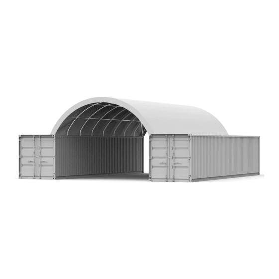
- Page 1 SHELTER ASSEMBLY MANUAL 33x40x12 Container Shelter Single truss...
-
Page 2: Parts List
PARTS LIST Part Code Description Left base plate Rigth base plate Top bent tube Middle bent tube Sidewall bent tube Connection purlin Support tube Clip Lower tensioning tube for roof cover 2 Groups Roof cover Bolt M8x70 Bolt M10x80 ∮ 32 Plastic plug for end of tensioning tube Ropes 1 dozen Ratchet strap (To tie down ratchet) -
Page 3: Specifications
SPECIFICATIONS Width: 33 ft Length: 40 ft Height: 12 ft IMPORTANT: READ MANUAL FIRST Improper site preparation, assembly and maintenance may invalidate warranty and cause unnecessary and costly mistakes. If you have any questions, contact your local dealer. For an easy assembly process, we have identified each individual component with the part code as indicated in the parts list. -
Page 4: Installation Process
EQUIPMENT AND TOOLS FOR INSTALLATION 1. Measuring tape 2. Alignment string 3. Step ladder 4. Welder 5. Sledgehammer 6. Wrench 7. Scissors INSTALLATION PROCESS A - BASE PLATES INSTALLATION Please refer to the Figure 1 to place the base plates. Figure 1 1. - Page 5 B - FRAME INSTALLATION (Refer to figure 2 for the full diagram) Figure 2 1. Connect the Top bent tube (part code 1), the Middle Bent Tube (part code 2) and the Sidewall Bent Tube (part code 3) with the Bolt M8x70 (part code 9); these make one group of arches.
- Page 6 3. After installing the first two arches, connect the Connection purlin (part code 4) onto them using the Bolt M10x80 (part code 10). There are 5 pieces of Connection purlins (part code 4) between each arch. 4. Install the Support tube (part code 5) using the Clip (part code 6) and the Bolt M8x70 (part code 9).
- Page 7 C - ROOF COVER INSTALLATION NOTE: DO NOT install the cover onto the frame of your building in high wind conditions. A slight breeze is the most advantageous for cover installation. To take advantage of the breeze, pull the cover up over the arches with the breeze blowing in the cover like a sail filled with air.
- Page 8 3. On the Roof cover, cut pockets over each ratchet on the base plates, then use the Ratchet strap (part code 13) to tie down the Lower tensioning tubes. Figure 6 4. Weld the Angle seats (part code 14) on each container and use the Rope (part code 11) to knit the cover on the two external arches.
- Page 9 Please, check our installation images and videos section by clicking the following link: https://drive.google.com/drive/u/3/folders/1p9FLejo-JIrkJPx5_Kp-hDcssOph2dWa NOTES: DO NOT LEAVE THE ROOF COVER UNATTACHED UNDER ANYCIRCUMSTANCES until the final assembly and tightening has been completed. The process is quite easy, but some tightening adjustments will be necessary to get a flat, tensioned roof cover.
Need help?
Do you have a question about the 33x40x12 and is the answer not in the manual?
Questions and answers