Advertisement
Quick Links
Advertisement

Related Manuals for Storage Canopy C4040S


Summary of Contents for Storage Canopy C4040S
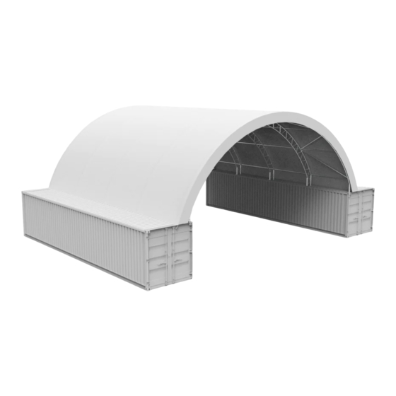
- Page 1 SHELTER ASSEMBLY MANUAL Model # W12xL12xH 4.5m C4040S Container Shelter...
-
Page 2: Specification
SPECIFICATION Width:12m Length:12m Height:4.5m IMPORTANT ---- READ MANUAL FIRST Improper site preparation, Assembly and Maintenance may invalidate warranty and cause unnecessary and costly mistake. If you have any questions contact your local dealer. For User Friendly assembly we have identified each individual component with the part code as indicated in the parts list. -
Page 3: Parts List
Parts List Part Code Description Top Bent Tube Side Bent Tube Lower Bent Tube Purlin Top Tension Device Clips Left Base Plate Right Base Plate Ratchet Nylon band for ratchet 2 组 Tensioning Tube Bolts M8x80 Bolts M10x80 Roof Cover Knitting Rope for Cover ∮... - Page 4 EQUIPEMNT AND TOOLS FOR INSTALIATION 1. Measuring tape 2. String for alignment 3. Step ladder 4. Welder 5. Sledge hammer 6. Wrench 7. Scissors INSTALLATION PROCESS A—BASE INSTALLATION Please refer to the diagram (Figure 1) to place the base plates. Figure 1 1.
- Page 5 Figure 2 Sketch Frame...
- Page 6 B—FRAME INSTALLATION Figure 3 1. As Figure 3 shown find Roof Bent Tube (No. 1), Side Bent Tube (No.2), Lower Bent Tube(No.3). To connect them by Bolts M8x80 ( No.11).Which makes one group of arch. Please NOTE the direction of the bolt. DO NOT install the bolts on the top of the truss where the fabric will rest.
- Page 7 Figure 4 3. After finishing installing the first two arches, connect the Connection purlins onto them by using screw M10x80(No.12).There are 7 pieces of Connection Purlins (No.4) between each arch. Then install the third arch into base plate and connect the purlins. Finally install the Top Tension Device (No.5) using bolt and Clip (No.6).
- Page 8 C—ROOF COVER INSTALLATION NOTE: DO NOT install the cover onto the frame of your building in high wind conditions. A slight breeze is the most advantageous for cover installation. To take advantage of the breeze, pull the cover up over the arches with breeze blowing in the cover like a sail filled with air. 1.
- Page 9 Figure 6 3. Weld the Angle Seats (No. 16) on each container and use Ropes (No. 14) to knit the cover on the two side arches, finally tie the Roof cover to the Angle seats. 4. Cut pockets over each ratchet on the base plates and put the Tensioning Tube for roof cover (No.
- Page 10 NOTE: DO NOT LEAVE THE ROOF COVER UNATTACHED UNDER ANY CIRCUMSTANCES until the final assembly and tightening has been completed. The process is quite easy. But some tightening adjustments will be necessary to produce a flat, tensioned roof cover. Please adjust the roof cover every month. Please Note: Please use the tape wrapped around the gap between the steel skeleton after installing.
Need help?
Do you have a question about the C4040S and is the answer not in the manual?
Questions and answers