
Related Manuals for Pilz PSSu E S 2DOR 10


Summary of Contents for Pilz PSSu E S 2DOR 10
- Page 1 PSSu E S 2DOR 10(-T) Decentralised system PSSuniversal I/O Operating Manual 22047-EN-05...
- Page 2 Preface This document is a translation of the original document. All rights to this documentation are reserved by Pilz GmbH & Co. KG. Copies may be made for internal purposes. Suggestions and comments for improving this documentation will be gratefully received.
-
Page 3: Table Of Contents
Removing an electronic module 5.3.3 Changing an electronic module during operation Section 6 Wiring General wiring guidelines 6.1.1 Mechanical connection of the base modules Terminal configuration Connecting the module Section 7 Operation Messages Display elements Operating Manual PSSu E S 2DOR 10(-T) 22047-EN-05... - Page 4 Contents 7.2.1 Display elements for module diagnostics 7.2.2 Display elements for output status Section 8 Technical details Section 9 Order reference Product Accessories Operating Manual PSSu E S 2DOR 10(-T) 22047-EN-05...
-
Page 5: Operating Manual Pssu E S 2Dor 10(-T)
Introduction Validity of documentation This documentation is valid for the products PSSu E S 2DOR 10 and PSSu E S 2DOR 10- T. It is valid until new documentation is published. This operating manual explains the function and operation, describes the installation and provides guidelines on how to connect the product. -
Page 6: Definition Of Symbols
It also highlights areas within the text that are of particular import- ance. INFORMATION This gives advice on applications and provides information on special fea- tures. Operating Manual PSSu E S 2DOR 10(-T) 22047-EN-05... -
Page 7: Overview
Current load capacity per output: 10,0 A LEDs for: – Switch status of each output – Module error For standard applications in system environment A and B T-type: PSSu E S 2DOR 10-T: for increased environmental requirements Operating Manual PSSu E S 2DOR 10(-T) 22047-EN-05... -
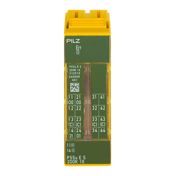
Page 8: Front View
2D code 3: Labelling strip for the terminal configuration on the base module 4: Status LEDs 5: Name of electronic module 6: Connection level 1 7: Connection level 2 8: Connection level 3 Operating Manual PSSu E S 2DOR 10(-T) 22047-EN-05... - Page 9 11: Round connection holes (connection levels 1, 2, 3 and 4) for connecting the signal lines 12: Mounting slot for colour marker to label the connection level (connection levels 1, 2, 3 and 4) Operating Manual PSSu E S 2DOR 10(-T) 22047-EN-05...
-
Page 10: Safety
PAS4000 from version 1.7.0 – We recommend that you always use the latest version (download from www.pilz.de). The PSSu E S 2DOR 10 module may be used in conjunction with the following base mod- ules: PSSu BP 2/16 S PSSu BP 2/16 C... -
Page 11: Safety Regulations
In safety-related applications, please comply with the mission time T in the safety-re- lated characteristic data. When decommissioning, please comply with local regulations regarding the disposal of electronic devices (e.g. Electrical and Electronic Equipment Act). Operating Manual PSSu E S 2DOR 10(-T) 22047-EN-05... -
Page 12: Function Description
DIN VDE 0110 overvoltage category 2 in a pro- tected industrial network Temperature monitoring The module provides the following diagnostic data: Start-up error Configuration error ST communication error Bus termination error Temperature error: too warm Temperature error: too hot Operating Manual PSSu E S 2DOR 10(-T) 22047-EN-05... -
Page 13: Functions
The relationship between the load current and the operating temperature is illustrated in the following derating diagram. The operating point should be below the characteristic curve. PSSu E S 2DOR 10: Derating diagram for the permitted ambient temperature T dependent on load current I T [°C]... -
Page 14: Reaction Times
Data access is via pre-defined I/O data types: I/O data name I/O data type I/O data element Meaning O0(11,21) ST_O_DO Data: BOOL Output data O0 O1(14,24) ST_O_DO Data: BOOL Output data O1 Operating Manual PSSu E S 2DOR 10(-T) 22047-EN-05... -
Page 15: Installation
5.1.1 Dimensions 25,2 mm 8,1 mm 52,1 mm (0.992") (0.319") (2.051") 25,2 mm 72,7 mm (0.992") (2.862") Operating Manual PSSu E S 2DOR 10(-T) 22047-EN-05... -
Page 16: Installing The Base Module
Push the base module back [2] until you hear it lock into position. On the mounting rail, slide the base module to the left until you hear the two lateral mounting hooks on the adjacent module lock into position [3]. Schematic representation: Operating Manual PSSu E S 2DOR 10(-T) 22047-EN-05... -
Page 17: Inserting And Removing An Electronic Module
This is how the base module is coded. The mechanics of the electronic modules are designed for 50 plug in/out cycles. Operating Manual PSSu E S 2DOR 10(-T) 22047-EN-05... -
Page 18: Inserting An Electronic Module
Installation 5.3.1 Inserting an electronic module Procedure: The electronic module must audibly lock into position [1]. Mark the electronic module using the labelling strips [2]. Schematic representation: Operating Manual PSSu E S 2DOR 10(-T) 22047-EN-05... -
Page 19: Removing An Electronic Module
The substitute values are used for the modules' FS outputs, with Valid Bits = FALSE. CAUTION! Sparking can cause interference and errors! Only change the module when the load is switched off! Operating Manual PSSu E S 2DOR 10(-T) 22047-EN-05... -
Page 20: Wiring
Use copper wiring. The terminal configuration as stated on the front plate applies for base modules with C- rail. The terminal configuration as stated in the technical documentation applies for all other base modules. Operating Manual PSSu E S 2DOR 10(-T) 22047-EN-05... -
Page 21: Mechanical Connection Of The Base Modules
– Insert the stripped cable into the round fixing hole [2], as far as it will go [5]. – Pull out the screwdriver [6]. – Check that the cable is firmly seated. Operating Manual PSSu E S 2DOR 10(-T) 22047-EN-05... - Page 22 To crimp the ferrules you can use crimp pliers (crimp form A or C) conforming to EN 60947-1, such as the PZ 1.5 or PZ 6.5 from Weidmüller, for example. – Maximum torque setting: 0.8 Nm Use copper wiring. Operating Manual PSSu E S 2DOR 10(-T) 22047-EN-05...
-
Page 23: Terminal Configuration
12-22: Not connected 13-23: C-rail supply (13-23-33-43 linked within the base module) 14: Output O1 Relay contact 2 24: Output O1 Relay contact 2 31–41, 32–42: Not connec- 33-43: C-rail supply 34-44: Not connected Operating Manual PSSu E S 2DOR 10(-T) 22047-EN-05... -
Page 24: Connecting The Module
Wiring Connecting the module Output circuit With C-rail Resistive load Switches 230 VAC n. c. n. c. n. c. n. c. Operating Manual PSSu E S 2DOR 10(-T) 22047-EN-05... -
Page 25: Operation
"too warm" theshold value, the relay contacts will close if the head module has set the status of the outputs to "1". Further information on PSSu error messages is available in the online help for the PSSuni- versal Assistant system software. Operating Manual PSSu E S 2DOR 10(-T) 22047-EN-05... -
Page 26: Display Elements
- - - 0 signal O0 (Out- 11, 21 put 1) Green 1 signal - - - 0 signal O1 (Out- 14, 24 put 2) 14 24 34 44 Green 1 signal Operating Manual PSSu E S 2DOR 10(-T) 22047-EN-05... -
Page 27: Technical Details
Max. power 2400 VA 2400 VA Relay contacts, DC1 at 24 V 24 V Min. current 10,00 mA 10,00 mA Max. current 10,0 A 10,0 A Max. power 240 W 240 W Operating Manual PSSu E S 2DOR 10(-T) 22047-EN-05... - Page 28 In accordance with the standard EN 60068-2-30, EN 60068-2-78 EN 60068-2-30, EN 60068-2-78 93 % r. h. at 40 °C 93 % r. h. at 40 °C Humidity Condensation during operation Not permitted Short-term Operating Manual PSSu E S 2DOR 10(-T) 22047-EN-05...
- Page 29 25,2 mm 25,2 mm Depth 60,2 mm 60,2 mm Weight 62 g 64 g Mechanical coding Type Colour Dark grey Dark grey Where standards are undated, the 2008-07 latest editions shall apply. Operating Manual PSSu E S 2DOR 10(-T) 22047-EN-05...
-
Page 30: Order Reference
Order reference Product Product type Features Order No. PSSu E S 2DOR 10 Electronic module, base type 312 510 PSSu E S 2DOR 10-T Electronic module, T-type 314 510 Accessories Base modules Product type Features Order no. PSSu BP 2/16 S...
Need help?
Do you have a question about the PSSu E S 2DOR 10 and is the answer not in the manual?
Questions and answers