
Related Manuals for Pilz PSSu E F 2DOR 8


Summary of Contents for Pilz PSSu E F 2DOR 8
- Page 1 PSSu E F 2DOR 8(-T)(-R) Decentralised system PSSuniversal I/O Operating Manual-21334-EN-13...
- Page 2 Preface This document is the original document. All rights to this documentation are reserved by Pilz GmbH & Co. KG. Copies may be made for the user's internal purposes. Suggestions and comments for improving this documenta- tion will be gratefully received.
-
Page 3: Table Of Contents
..............Wiring ............................General wiring guidelines ......................6.1.1 Mechanical connection of the base modules................Terminal configuration ......................Connecting the module......................Function test during commissioning ..................Operation ..........................Messages ..........................Display elements ........................Operating Manual PSSu E F 2DOR 8(-T)(-R) 21334-EN-13... - Page 4 Display elements for an output's FS enable ................7.2.3 Display elements for output status.................... Technical details ........................Safety characteristic data ......................Service life graphs ........................Order reference ........................Product ............................. Accessories ..........................Operating Manual PSSu E F 2DOR 8(-T)(-R) 21334-EN-13...
-
Page 5: Introduction
Introduction Validity of documentation This documentation is valid for the product types PSSu E F 2DOR 8, PSSu E F 2DOR 8-T and PSSu E F 2DOR 8-R. It is valid until new documentation is published. This operating manual explains the function and operation, describes the installation and provides guidelines on how to connect the product. -
Page 6: Definition Of Symbols
It also highlights areas within the text that are of particular import- ance. INFORMATION This gives advice on applications and provides information on special fea- tures. Operating Manual PSSu E F 2DOR 8(-T)(-R) 21334-EN-13... -
Page 7: Overview
The product has the following features: Relay contacts – N/O contact – Volt-free – Current load capacity per output: 8 A LEDs for: – Switch status of each output – Module error Operating Manual PSSu E F 2DOR 8(-T)(-R) 21334-EN-13... -
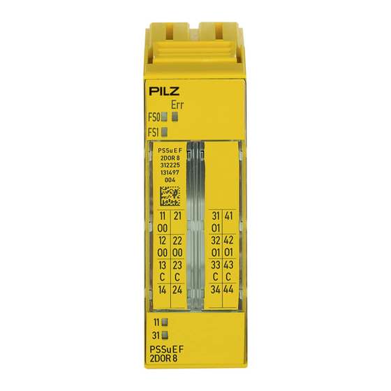
Page 8: Front View
Overview For failsafe applications in system environment A and B T-type: PSSu E F 2DOR 8-T: for increased environmental requirements R-type: PSSu E F 2DOR 8-R: for railway applications Front view PSSu E F 2DOR 8 312225 000000 14 24... - Page 9 11: Round connection holes (connection levels 1, 2, 3 and 4) for connecting the signal lines 12: Mounting slot for colour marker to label the connection level (connection levels 1, 2, 3 and 4) Operating Manual PSSu E F 2DOR 8(-T)(-R) 21334-EN-13...
-
Page 10: Safety
The module may be used for failsafe applications in system environment A and B (automa- tion system PSS 4000). The modules PSSu E F 2DOR 8 and PSSu E F 2DOR 8-T may be used as a safety com- ponents in accordance with the Lifts Directive 95/16/EC in accordance with the require- ments of EN 81-1/2:1998+A3:2009, EN 81-20:2015, EN 81-50:2015, EN 81-22:2014 and... -
Page 11: Safety Regulations
PSSu BP 2/16 C PSSu BP-C 2/16 S PSSu BP-C 2/16 C The PSSu E F 2DOR 8-T and PSSu E F 2DOR 8-R modules may be used in conjunction with the following base modules: PSSu BP 2/16 S-T PSSu BP 2/16 C-T... -
Page 12: Warranty And Liability
In safety-related applications, please comply with the mission time T in the safety-related characteristic data. When decommissioning, please comply with local regulations regarding the disposal of electronic devices (e.g. Electrical and Electronic Equipment Act). Operating Manual PSSu E F 2DOR 8(-T)(-R) | 12 21334-EN-13... -
Page 13: Function Description
+ 24 V DC Module Supply + 5 V DC Data (FS) (C-Rail) 13 23 33 43 Module features 4.2.1 Functions Module supply The module supply provides the module with voltage. Outputs Operating Manual PSSu E F 2DOR 8(-T)(-R) | 13 21334-EN-13... - Page 14 The relationship between the load current and the operating temperature is illustrated in the following derating diagram. The operating point should be below the characteristic curve. PSSu E F 2DOR 8: Derating diagram for the permitted ambient temperature T dependent on load current I T[°C]...
-
Page 15: Integrated Protection Mechanisms
Read/write access through the standard bus system (configured per FS output): "&" configuration (local enable principle) Optimisation of ST process image by combining adjacent bits of the same type. “*” configuration Operating Manual PSSu E F 2DOR 8(-T)(-R) | 15 21334-EN-13... -
Page 16: Addresses In The Process Image
Data access is via pre-defined I/O data types: I/O data name I/O data type I/O data element Meaning O0(11,21) FS_O_DO Data: SAFEBOOL Output data O0 O1(31,32) FS_O_DO Data: SAFEBOOL Output data O1 Operating Manual PSSu E F 2DOR 8(-T)(-R) | 16 21334-EN-13... -
Page 17: Installation
5.1.1 Dimensions 25,2 mm 8,1 mm 52,1 mm (0.992") (0.319") (2.051") 25,2 mm 72,7 mm (0.992") (2.862") Operating Manual PSSu E F 2DOR 8(-T)(-R) | 17 21334-EN-13... -
Page 18: Installing The Base Module
Push the base module back [2] until you hear it lock into position. On the mounting rail, slide the base module to the left until you hear the two lateral mounting hooks on the adjacent module lock into position [3]. Schematic representation: Operating Manual PSSu E F 2DOR 8(-T)(-R) | 18 21334-EN-13... -
Page 19: Inserting And Removing An Electronic Module
This is how the base module is coded. The mechanics of the electronic modules are designed for 50 plug in/out cycles. Operating Manual PSSu E F 2DOR 8(-T)(-R) | 19 21334-EN-13... -
Page 20: Inserting An Electronic Module
Installation 5.3.1 Inserting an electronic module Procedure: The electronic module must audibly lock into position [1]. Mark the electronic module using the labelling strips [2]. Schematic representation: Operating Manual PSSu E F 2DOR 8(-T)(-R) | 20 21334-EN-13... -
Page 21: Removing An Electronic Module
– The substitute values are used for the modules' FS outputs, with Valid Bits = FALSE. CAUTION! Sparking can cause interference and errors! Only change the module when the load is switched off! Operating Manual PSSu E F 2DOR 8(-T)(-R) | 21 21334-EN-13... -
Page 22: Wiring
– Use a screwdriver to loosen the screw on the screw terminal [1] – Insert the stripped cable into the round fixing hole [2], as far as it will go. – Tighten up the screw on the screw terminal. Operating Manual PSSu E F 2DOR 8(-T)(-R) | 22 21334-EN-13... - Page 23 – Inputs/outputs on the counter modules: 1.5 mm (AWG16) – Analogue inputs/outputs: 1.5 mm (AWG16) – Communication cables: 1.5 mm (AWG16) – Test pulse outputs: 1.5 mm (AWG16) – Power supply: 2.5 mm (AWG12) – Functional earth: 2.5 mm (AWG12) Operating Manual PSSu E F 2DOR 8(-T)(-R) | 23 21334-EN-13...
-
Page 24: Terminal Configuration
14-24: Not assigned 31: Output O1 Relay contact 1 41: Not assigned 32-42: Output O1 Relay contact 2 (32-42 linked within the base module) 34-44: Not assigned Operating Manual PSSu E F 2DOR 8(-T)(-R) | 24 21334-EN-13... - Page 25 (12-22 linked within the base module) 14-24: Not assigned 31: Output O1 Relay contact 1 41: Not assigned 32-42: Output O1 Relay contact 2 (32-42 linked within the base module) 34-44: Not assigned Operating Manual PSSu E F 2DOR 8(-T)(-R) | 25 21334-EN-13...
-
Page 26: Connecting The Module
Wiring Connecting the module Output circuit With C-rail Single-channel actuator Switches 230 VAC n. c. n. c. Dual-channel actuator Switches 230 VAC n. c. n. c. Operating Manual PSSu E F 2DOR 8(-T)(-R) | 26 21334-EN-13... -
Page 27: Function Test During Commissioning
INFORMATION The short circuit test must be performed on the load and not on the output terminal. Operating Manual PSSu E F 2DOR 8(-T)(-R) | 27 21334-EN-13... -
Page 28: Operation
Reset the module and stop the af- tion in the control cabinet or pre- fected I/O-Groups (SafetyBUS p) vent overload. Relay control error Error during cyclical monitoring Change faulty relay module. test of the relay coils Operating Manual PSSu E F 2DOR 8(-T)(-R) | 28 21334-EN-13... -
Page 29: Display Elements
FS outputs are driven via a standard bus system using the local enable principle. An FS en- able is assigned to each of these FS outputs. The status of that enable is displayed via the enable LEDs (“FS0” and “FS1”). Operating Manual PSSu E F 2DOR 8(-T)(-R) | 29 21334-EN-13... -
Page 30: Display Elements For Output Status
- - - 0 signal O0 (Out- put 1) 12-22 Green 1 signal - - - 0 signal O1 (Out- put 2) 32-42 14 24 34 44 Green 1 signal Operating Manual PSSu E F 2DOR 8(-T)(-R) | 30 21334-EN-13... -
Page 31: Technical Details
Permitted loads inductive, resistive inductive, resistive inductive, resistive Relay outputs 312225 314225 315225 Number of relay outputs Utilisation category In accordance with the EN 60947-4-1 EN 60947-4-1 EN 60947-4-1 standard Operating Manual PSSu E F 2DOR 8(-T)(-R) | 31 21334-EN-13... - Page 32 External contact fuse pro- tection, safety contacts In accordance with the standard VDE 0660 VDE 0660 VDE 0660 10 A 10 A 10 A Blow-out fuse, quick Blow-out fuse, slow Operating Manual PSSu E F 2DOR 8(-T)(-R) | 32 21334-EN-13...
- Page 33 – – -40 ... +70 °C Storage temperature In accordance with the standard EN 60068-2-1/-2 EN 60068-2-1/-2 EN 60068-2-1/-2 -25 - 70 °C -40 - 70 °C Temperature range – Operating Manual PSSu E F 2DOR 8(-T)(-R) | 33 21334-EN-13...
- Page 34 In accordance with the standard – – EN 50155 Class – – S2, C1, C2 Airgap creepage In accordance with the standard EN 60664-1 EN 60664-1 EN 50124-1 Overvoltage category Pollution degree Operating Manual PSSu E F 2DOR 8(-T)(-R) | 34 21334-EN-13...
-
Page 35: Safety Characteristic Data
1-channel 2-channel PL e Cat. 4 SIL CL 3 7,78E-10 SIL 3 1,34E-06 All the units used within a safety function must be considered when calculating the safety characteristic data. Operating Manual PSSu E F 2DOR 8(-T)(-R) | 35 21334-EN-13... -
Page 36: Service Life Graphs
The wear is mainly caused by the electrical load; the mechanical load is negli- gible. Switching current (A) Fig.: Service life graph / Switching capability 24 VDC / 250 VAC Operating Manual PSSu E F 2DOR 8(-T)(-R) | 36 21334-EN-13... - Page 37 With capacitive loads, any power surges that occur must be noted. With DC contact- ors, use flywheel diodes for spark suppression. We recommend you use semiconductor outputs to switch 24 VDC loads. Operating Manual PSSu E F 2DOR 8(-T)(-R) | 37 21334-EN-13...
-
Page 38: Order Reference
314 630 PSSu BP-C 2/16 C Base module with C-rail and cage clamp terminals 312 631 PSSu BP-C 2/16 C-T Base module with C-rail and cage clamp terminals, T-type 314 631 Operating Manual PSSu E F 2DOR 8(-T)(-R) | 38 21334-EN-13... - Page 39 Front cover Support Technical support is available from Pilz round the clock. Americas Australia Scandinavia +45 74436332 Brazil +61 3 95600621 +55 11 97569-2804 Spain Canada Europe +34 938497433 +1 888-315-PILZ (315-7459) Austria Switzerland Mexico +43 1 7986263-0 +41 62 88979-30...
Need help?
Do you have a question about the PSSu E F 2DOR 8 and is the answer not in the manual?
Questions and answers