
Related Manuals for R&S RTC1002


Summary of Contents for R&S RTC1002
- Page 1 ® R&S RTC1000 Digital Oscilloscope Getting Started (=S×^2) 1335734602 Version 06 Distributed by: Sie haben Fragen oder wünschen eine Beratung? Angebotsanfrage unter +49 7121 / 51 50 50 oder über info@datatec.eu...
- Page 2 ® This manual describes the following R&S RTC1000 models: ● R&S ® RTC1002 (1335.7500K02) © 2021 Rohde & Schwarz GmbH & Co. KG Mühldorfstr. 15, 81671 München, Germany Phone: +49 89 41 29 - 0 Email: info@rohde-schwarz.com Internet: www.rohde-schwarz.com Subject to change – data without tolerance limits is not binding.
-
Page 3: Table Of Contents
® Contents R&S RTC1000 Contents 1 Safety Information..............5 1.1 Safety Instructions................5 1.2 Korea Certification Class A..............6 2 Documentation Overview............7 2.1 Manuals and Instrument Help..............7 2.2 Data Sheet and Brochure..............8 2.3 Calibration Certificate................8 2.4 Release Notes, Open Source Acknowledgment........ 8 3 Preparing for Use..............9 3.1 Unpacking and Checking the Instrument........... - Page 4 ® Contents R&S RTC1000 Getting Started 1335.7346.02 ─ 06...
-
Page 5: Safety Information
® Safety Information R&S RTC1000 Safety Instructions Safety Information The R&S RTC1000 digital oscilloscope is designed for measurements on circuits that are only indirectly connected to the mains or not connected at all. It is not rated for any measurement category. The instrument is rated for pollution degree 2 - for indoor, dry location use where only non-conductive pollution occurs. -
Page 6: Korea Certification Class A
® Safety Information R&S RTC1000 Korea Certification Class A An unsuitable operating site or test setup can damage the instrument and con- nected devices. Ensure the following operating conditions before you switch on the instrument: ● Read and observe the "Basic Safety Instructions" brochure and the safety instructions in the manuals. -
Page 7: Documentation Overview
® Documentation Overview R&S RTC1000 Manuals and Instrument Help Documentation Overview This section provides an overview of the R&S RTC1000 user documentation. Manuals and Instrument Help You find the manuals on the product page at: www.rohde-schwarz.com/manual/rtc1000 Getting started manual Introduces the R&S RTC1000 and describes how to set up the product. A printed English version is included in the delivery. -
Page 8: Data Sheet And Brochure
® Documentation Overview R&S RTC1000 Release Notes, Open Source Acknowledgment Service manual Describes the performance test for checking the rated specifications, module replacement and repair, firmware update, troubleshooting and fault elimination, and contains mechanical drawings and spare part lists. The service manual is available for registered users on the global Rohde &... -
Page 9: Preparing For Use
® Preparing for Use R&S RTC1000 Unpacking and Checking the Instrument Preparing for Use Unpacking and Checking the Instrument 1. Inspect the package for damage. If the packaging material shows any signs of stress, notify the carrier who delivered the instrument. 2. -
Page 10: Positioning The Instrument
® Preparing for Use R&S RTC1000 Positioning the Instrument Positioning the Instrument The instrument is designed for use under laboratory conditions. It can be used in standalone operation on a bench top or can be installed in a rack. For standalone operation, place the instrument on a horizontal bench with even, flat surface. -
Page 11: Starting The Instrument
® Preparing for Use R&S RTC1000 Starting the Instrument Risk of instrument damage due to overheating An insufficient airflow can cause the R&S RTC1000 to overheat, which can impair the measurement results, disturb the operation, and even cause damage. ● Ensure that all fan openings are unobstructed and that the airflow perfo- rations are unimpeded. -
Page 12: Starting Up And Shutting Down
® Preparing for Use R&S RTC1000 Starting the Instrument 2. Connect the power cable to the socket outlet. 3. Switch the main power switch at the rear of the instrument to position I. The [ON/OFF] key lights up when the instrument is in standby mode. The key is located next to the upper right corner of the screen. -
Page 13: Powering Off
® Preparing for Use R&S RTC1000 Replacing the Fuse 3.3.3 Powering Off Powering off is required only if the instrument must be disconnected from all power supplies. 1. If the instrument is running, press the [ON/OFF] key on the front panel to shut down the instrument. - Page 14 ® Preparing for Use R&S RTC1000 Replacing the Fuse Risk of electric shock The fuse is part of the main power supply. Therefore, handling the fuse while power is on can lead to electric shock. Before opening the fuse holder, make sure that the instrument is switched off and disconnected from all power supplies.
-
Page 15: Instrument Tour
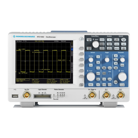
® Instrument Tour R&S RTC1000 Front Panel Instrument Tour Front Panel Figure 4-1 shows the front panel of the R&S RTC1000. The function keys are grouped in functional blocks to the right of the display. Figure 4-1: Front view of the R&S RTC1000 1 = Display 2 = Softkeys and menu 3 = [ON/OFF] key... -
Page 16: Input Connectors
® Instrument Tour R&S RTC1000 Front Panel 9 = Connector for the logic probe (option R&S RTC-B1) 10 = Multi-purpose BNC connector [Aux Out] 11 = USB connector 4.1.1 Input Connectors BNC inputs (6, 7) The R&S RTC1000 has two channel inputs (6) to connect the input signals. The external trigger input (7) is used to control the measurement by an external sig- nal. -
Page 17: Other Connectors On The Front Panel
® Instrument Tour R&S RTC1000 Front Panel Risk of injury and instrument damage The instrument is not rated for any measurement category. When measur- ing in circuits with transient overvoltages of category II, III or IV circuits, make sure that no such overvoltages reach the R&S RTC1000 input. Therefore, use only probes that comply with DIN EN 61010-031. -
Page 18: Rear Panel
® Instrument Tour R&S RTC1000 Rear Panel [Pattern Generator] (8) Connectors for the pattern generator P0, P1, P2, P3. [Probe Comp.] (8) Probe compensation terminal to support adjustment of passive probes to the oscilloscope channel. Square wave signal for probe compensation. Ground connector for probes. - Page 19 ® Instrument Tour R&S RTC1000 Rear Panel Figure 4-2: Rear panel view of R&S RTC1000 1 = AC power supply connector and main power switch 2 = USB connector, type B 3 = LAN connector 4 = not used 5 = Kensington lock slot to secure the instrument against theft AC supply: mains connector and main power switch (1) The instrument supports a wide range power supply.
- Page 20 ® Instrument Tour R&S RTC1000 Rear Panel [LAN] (3) 8-pin connector RJ-45 used to connect the instrument to a Local Area Network (LAN). It supports up to 100 Mbit/s. Getting Started 1335.7346.02 ─ 06...
-
Page 21: Contacting Customer Support
® Contacting Customer Support R&S RTC1000 Contacting Customer Support Technical support – where and when you need it For quick, expert help with any Rohde & Schwarz product, contact our customer support center. A team of highly qualified engineers provides support and works with you to find a solution to your query on any aspect of the operation, program- ming or applications of Rohde &...
Need help?
Do you have a question about the RTC1002 and is the answer not in the manual?
Questions and answers