
Subscribe to Our Youtube Channel
Related Manuals for R&S RTA4000


Summary of Contents for R&S RTA4000
- Page 1 ® R&S RTA4000 Oscilloscope User Manual (=SÜð2) 1335789802 Version 08 Distributed by: Sie haben Fragen oder wünschen eine Beratung? Angebotsanfrage unter +49 7121 / 51 50 50 oder über info@datatec.eu...
- Page 2 ® This manual describes the following R&S RTA4000 models with firmware version 1.7xx: ● ® R&S RTA4004 (1335.7700K04) In addition to the base unit, the following options are described: ● ® R&S RTA-K1, I²C/SPI trigger and decode ● ® R&S RTA-K2, UART/RS232 trigger and decode ●...
-
Page 3: Table Of Contents
® Contents R&S RTA4000 Contents 1 Safety and regulatory information............17 Safety instructions......................17 Labels on the product....................22 Warning messages in the documentation..............22 Korea certification class A..................23 2 Preface....................24 Documentation overview....................24 2.1.1 Manuals and instrument help..................24 2.1.2 Data sheet and brochure....................25 2.1.3... - Page 4 ® Contents R&S RTA4000 Using the touchscreen....................36 4.3.1 Accessing functionality using the main menu............... 36 4.3.2 Accessing functionality using shortcuts.................38 4.3.3 Entering data.........................38 4.3.4 Using gestures......................39 Front panel keys......................40 4.4.1 Action controls.......................40 4.4.2 Analysis controls......................41 Using the toolbar......................42 Quick access.......................
- Page 5 ® Contents R&S RTA4000 Shortcuts for trigger settings..................79 General trigger settings....................80 Edge trigger......................... 82 Edge A/B trigger......................84 Width trigger........................ 85 Video trigger........................ 88 Pattern trigger......................90 Runt trigger........................93 6.10 Rise time trigger......................94 6.11 Timeout trigger......................96 6.12 Actions on trigger....................... 98 7 Waveform analysis................101...
- Page 6 ® Contents R&S RTA4000 Search........................130 7.5.1 Search conditions and results..................130 7.5.2 General search settings....................133 7.5.3 Edge search........................ 135 7.5.4 Width search....................... 136 7.5.5 Peak search........................ 137 7.5.6 Rise/fall time search....................137 7.5.7 Runt setup........................139 7.5.8 Data2Clock........................140 7.5.9 Pattern search......................142 7.5.10...
- Page 7 ® Contents R&S RTA4000 9.3.3 Peak list and markers....................185 9.3.4 Display settings for spectrum and spectrogram............190 Spectrum analysis and spectrogram (option R&S RTA-K37)....... 191 9.4.1 FFT menu with spectrum analysis................192 9.4.2 Spectrogram........................193 9.4.3 Peak list and markers....................195 9.4.4 Display settings for spectrum and spectrogram............
- Page 8 ® Contents R&S RTA4000 11.6 Setting the date, time and language................236 11.7 Options........................238 11.7.1 Activating options......................238 11.8 Updating the firmware....................239 12 Network connections and remote operation........240 12.1 LAN connection......................240 12.1.1 LAN settings........................240 12.2 USB connection......................243 12.2.1 USB TMC........................
- Page 9 ® Contents R&S RTA4000 13.3 I²C (option R&S RTA-K1)...................268 13.3.1 The I²C protocol......................269 13.3.2 I²C configuration......................270 13.3.3 I²C trigger........................272 13.3.4 I²C decode results....................... 274 13.3.5 I²C label list......................... 276 13.4 UART / RS232 (option R&S RTA-K2)............... 277 13.4.1 The UART / RS232 interface..................277...
- Page 10 ® Contents R&S RTA4000 13.8.2 MIL-STD-1553 configuration..................323 13.8.3 MIL-STD-1553 trigger....................325 13.8.4 MIL-STD-1553 decode results..................330 13.8.5 MIL-STD-1553 label list....................331 13.9 ARINC 429 (option R&S RTA-K7)................331 13.9.1 ARINC 429 basics.......................331 13.9.2 ARINC 429 configuration.................... 332 13.9.3 ARINC 429 trigger.......................334 13.9.4...
- Page 11 ® Contents R&S RTA4000 14.7.3 Turn ON/OFF time.......................381 14.7.4 Safe operating area (S.O.A.)..................384 15 Logic analyzer (option R&S RTA-B1, MSO)........392 15.1 Short menu for logic channels................392 15.2 Logic analyzer settings.................... 394 15.3 Triggering on logic channels................... 396 15.4 Analyzing logic channels..................
- Page 12 ® Contents R&S RTA4000 17.2.4 Function generator...................... 430 17.3 Common commands....................430 17.4 Waveform setup......................433 17.4.1 Automatic setup......................434 17.4.2 Starting and stopping acquisition................434 17.4.3 Vertical settings......................435 17.4.4 Passive probes......................442 17.4.5 Active probes......................443 17.4.6 R&S ProbeMeter......................450 17.4.7...
- Page 13 ® Contents R&S RTA4000 17.7.3 Cursor measurements....................529 17.8 Applications.......................536 17.8.1 General........................536 17.8.2 Mask testing........................ 536 17.8.3 FFT analysis........................542 17.8.4 Spectrum analysis and spectrogram (options R&S RTA-K18/K37)......549 17.8.5 XY-Waveforms......................557 17.8.6 Digital voltmeter......................558 17.8.7 Trigger counter......................560 17.8.8 Bode plot (option R&S RTA-K36)................561 17.9...
- Page 14 ® Contents R&S RTA4000 17.12.1 General........................714 17.12.2 Probe adjustment......................716 17.12.3 Report......................... 717 17.12.4 Consumption....................... 718 17.12.5 Dynamic ON resistance....................720 17.12.6 Power efficiency......................721 17.12.7 Current harmonic......................723 17.12.8 Inrush current......................729 17.12.9 Modulation analysis.....................730 17.12.10 Turn on/off........................734 17.12.11...
- Page 15 ® Contents R&S RTA4000 Annex....................804 A Remote control basics...............804 SCPI command structure..................804 A.1.1 Syntax for common commands...................804 A.1.2 Syntax for instrument-specific commands..............805 A.1.3 SCPI parameters......................806 A.1.4 Overview of syntax elements..................809 A.1.5 Structure of a command line..................810 A.1.6...
- Page 16 ® Contents R&S RTA4000 User Manual 1335.7898.02 ─ 08...
-
Page 17: Safety And Regulatory Information
17. Intended use The R&S RTA4000 oscilloscope is designed for measurements on circuits that are only indirectly connected to the mains or not connected at all. It is not rated for any mea- surement category. The product is intended for the development, production and verification of electronic components and devices in industrial, administrative, and laboratory environments. - Page 18 ® Safety and regulatory information R&S RTA4000 Safety instructions In these safety instructions, the term "product" covers instruments (oscilloscopes), probes and their accessories. Lifting and carrying the instrument Check the data sheet for the maximum weight of the instrument. A single person can only carry a maximum of 18 kg safely depending on age, gender and physical condi- tion.
- Page 19 ® Safety and regulatory information R&S RTA4000 Safety instructions ment such as household appliances and similar loads. Be aware that electrically pow- ered products have risks, such as electric shock, fire, personal injury or even death. Take the following measures for your safety: ●...
- Page 20 ® Safety and regulatory information R&S RTA4000 Safety instructions ● When working with high voltages and current probes, observe the additional oper- ating conditions specified in this safety instructions. ● The probe pins are extremely pointed and can easily penetrate clothes and the skin.
- Page 21 ® Safety and regulatory information R&S RTA4000 Safety instructions Measurement categories IEC 61010-2-030 defines measurement categories that rate instruments on their ability to resist short transient overvoltages that occur in addition to the working voltage. Use the measurement setup only in electrical environments for which they are rated.
-
Page 22: Labels On The Product
® Safety and regulatory information R&S RTA4000 Warning messages in the documentation Potential hazard Read the product documentation to avoid personal injury or product damage. Electrical hazard Indicates live parts. Risk of electric shock, fire, personal injury or even death. -
Page 23: Korea Certification Class A
® Safety and regulatory information R&S RTA4000 Korea certification class A NOTICE Potential risks of damage. Could result in damage to the supported product or to other property. 1.4 Korea certification class A 이 기기는 업무용(A급) 전자파 적합기기로서 판매자 또는 사용자는 이 점을 주의하시기... -
Page 24: Preface
You find the manuals on the product page at: www.rohde-schwarz.com/manual/rta4000 Getting started manual Introduces the R&S RTA4000 and describes how to set up the product. A printed Eng- lish version is included in the delivery. User manual Contains the description of all instrument modes and functions. It also provides an... -
Page 25: Data Sheet And Brochure
Conventions used in the documentation 2.1.2 Data sheet and brochure The data sheet contains the technical specifications of the R&S RTA4000. It also lists the options with their order numbers and optional accessories. The brochure provides an overview of the instrument and deals with the specific characteristics. -
Page 26: Conventions For Procedure Descriptions
® Preface R&S RTA4000 Conventions used in the documentation 2.2.2 Conventions for procedure descriptions When operating the instrument, several alternative methods may be available to per- form the same task. In this case, the procedure using the touchscreen is described. -
Page 27: Getting Started
4. Check the equipment for damage. If the delivery is incomplete or equipment is damaged, contact Rohde & Schwarz. Delivery contents The delivery package contains the following items: ● R&S RTA4000 oscilloscope ● R&S RT-ZP10 probes (4x) ● Country-specific power cable ●... -
Page 28: Setting Up The Product
® Getting started R&S RTA4000 Preparing for use Electromagnetic compatibility classes The electromagnetic compatibility (EMC) class indicates where you can operate the product. The EMC class of the product is given in the data sheet under "General data". ● Class B equipment is suitable for use in: –... -
Page 29: Considerations For Test Setup
Design and implement an efficient ventilation concept for the rack. To mount the R&S RTA4000 in a rack 1. Use an adapter kit that fits the dimensions of the R&S RTA4000 to prepare the instrument for rack mounting. For information on the dimensions, see data sheet. -
Page 30: Connecting To Power
3.1.6 Connecting to power For safety information, see "Connecting to power and grounding" on page 18. The R&S RTA4000 can be used with different AC power voltages and adapts itself automatically to it. The nominal ranges are: ● 100 V to 240 V AC at 50 Hz to 60 Hz, with maximal 10% voltage fluctuation on line ●... -
Page 31: Instrument Tour
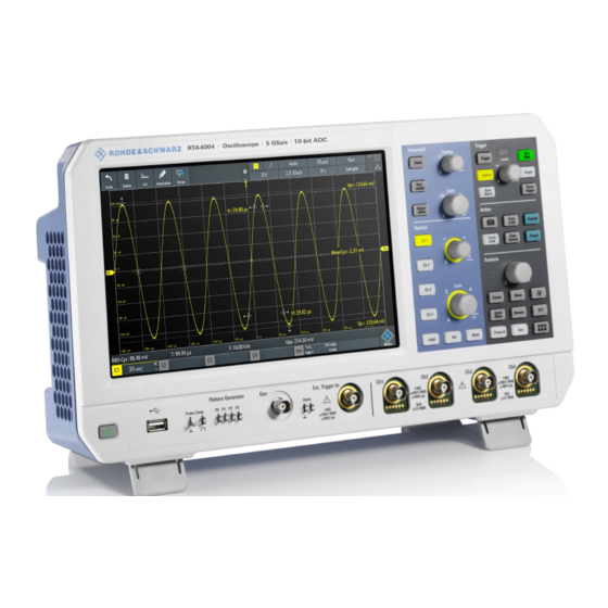
3.2 Instrument tour 3.2.1 Front view Figure 3-1 shows the front panel of the R&S RTA4000. The function keys are grouped in functional blocks to the right of the display. Figure 3-1: Front panel of R&S RTA4000 with 4 input channels... - Page 32 Input connectors BNC inputs (4 and 5) The R&S RTA4000 has two or four channel inputs (4) to connect the input signals. The external trigger input (5) is used to control the measurement by an external signal. The trigger level can be set from -5 V to 5 V.
-
Page 33: Side View
800 mV (Vpp) is 400 MHz. 3.2.3 Rear view Figure 3-3 shows the rear panel of the R&S RTA4000 with its connectors. User Manual 1335.7898.02 ─ 08... - Page 34 ® Getting started R&S RTA4000 Instrument tour Figure 3-3: Rear panel view of R&S RTA4000 1 = Aux Out connector 2 = USB connector, type B 3 = LAN connector 4 = AC power supply connector and main power switch...
-
Page 35: Operating Basics
The touchscreen display of the instrument shows the waveforms and measurement results, and also information and everything that you need to control the instrument. Figure 4-1: Display of the R&S RTA4000 with 4 channels 1 = Toolbar 2 = Trigger source, main trigger parameter (here: slope for edge trigger), trigger level... -
Page 36: Selecting The Application
4.3.1 Accessing functionality using the main menu Using the touchscreen of the R&S RTA4000 is as easy as using your mobile phone. To open the main menu, tap the "Menu" button - that is the R&S logo in the right bottom corner of the display. - Page 37 ® Operating basics R&S RTA4000 Using the touchscreen Figure 4-2: Open the main menu and select a menu item Figure 4-3: Switch on or off (left) and select a parameter value (right) ► To close the menu: User Manual 1335.7898.02 ─ 08...
-
Page 38: Accessing Functionality Using Shortcuts
® Operating basics R&S RTA4000 Using the touchscreen Tap "Back", or tap into the diagram outside the menu. 4.3.2 Accessing functionality using shortcuts The labels in information bar at the top of the display, the channel labels and also the results at the bottom provide shortcuts to the most important settings. -
Page 39: Using Gestures
® Operating basics R&S RTA4000 Using the touchscreen Figure 4-5: Enter numerical value and unit 4.3.4 Using gestures Drag one finger Drag horizontally in the diagram to change the horizontal position of all waveforms. In frequency domain, the center frequency is changed. -
Page 40: Front Panel Keys
® Operating basics R&S RTA4000 Front panel keys Spread or pinch two fingers in horizontal direction to change the horizontal scale of all waveforms. In frequency domain, the frequency span is changed. Swipe two fingers If the history option R&S RTA-K15 is installed, swipe two fingers in the diagram to scrolls through the history segments. -
Page 41: Analysis Controls
® Operating basics R&S RTA4000 Front panel keys [Clear Screen] Deletes all waveforms, annotations and the measurement results of deleted wave- forms. All settings remain unchanged. Remote command: on page 592 DISPlay:CLEar[:SCReen] 4.4.2 Analysis controls The controls in the [Analysis] functional block open various menus for signal analysis. -
Page 42: Using The Toolbar
® Operating basics R&S RTA4000 Using the toolbar Note: Channels other than the selected one are switched off in quick measurement mode. When you activate quick measurements, cursor measurements are automati- cally deactivated. Deactivate quick measurements before selecting the cursors. -
Page 43: Quick Access
® Operating basics R&S RTA4000 Quick access 4. Close the dialog box. 4.6 Quick access If the measurement task requires to change the settings from different menus repeat- edly, you can use the "QuickAccess". The "QuickAccess" is a user-defined menu, which can be added to the toolbar. -
Page 44: Menu History
The menu history is another way to speed up and simplify the usage of the R&S RTA4000. The menu history is also a user-defined menu, which can be added to the toolbar. It logs all menus that you used during the current session. -
Page 45: Getting Help
® Operating basics R&S RTA4000 Getting help 4.8 Getting help In most menus and dialogs, graphics explain the meaning of the selected setting. For further information, you can open the help, which provides functional description of selected setting. To open the help window 1. -
Page 46: Waveform Setup
® Waveform setup R&S RTA4000 Connecting probes and displaying a signal 5 Waveform setup This chapter describes how to connect and set up probes, to adjust the horizontal and vertical settings, and to control the acquisition. 5.1 Connecting probes and displaying a signal... -
Page 47: Horizontal Setup
® Waveform setup R&S RTA4000 Horizontal setup 1 Ω resistor and a 10:1 probe is used, the V/A-value of the resistor is 1 V/A. The attenuation factor of the probe is 0.1, and the resulting current probe attenuation is 100 mV/A. - Page 48 ® Waveform setup R&S RTA4000 Horizontal setup the horizontal acquisition window to the waveform section of interest, you can use the following parameters: ● The horizontal position defines the time distance of the trigger point (the zero point of the diagram) to the reference point. Changing the horizontal position, you can move the trigger point, even outside the screen.
-
Page 49: Horizontal Controls
® Waveform setup R&S RTA4000 Horizontal setup 5.2.1 HORIZONTAL controls [Position] Changes the trigger position, the time distance from the trigger point to the reference point (trigger offset). The trigger point is the zero point of the diagram. Thus, you can set the trigger point even outside the diagram and analyze the signal some time before or after the trigger. -
Page 50: Shortcuts For Horizontal Settings
® Waveform setup R&S RTA4000 Horizontal setup [Horizontal] Opens the menu to configure horizontal scale, position, and reference point. The cur- rent scale and position is shown in the top information bar. If zoom is active, you can find also the zoom scale and zoom position in this menu. -
Page 51: Vertical Setup
® Waveform setup R&S RTA4000 Vertical setup The reference point defines which part of the waveform is shown. By default, the refer- ence point is displayed in the center of the window, and you can move it to the left or right. -
Page 52: Vertical Controls
® Waveform setup R&S RTA4000 Vertical setup There are several ways to adjust vertical settings: ● Use the controls in the Vertical functional block of the front panel to select the channel, to scale the waveform, and to set the position. - Page 53 ® Waveform setup R&S RTA4000 Vertical setup [Offset/Position (upper knob)] The upper vertical knob adjusts the following, depending on the selected waveform: ● Offset or position of an analog channel (adjustable: main menu > "Vertical"). The visual effect is the same. While the offset sets a voltage, position is a graphical set- ting given in divisions.
-
Page 54: Short Menu For Analog Channels
® Waveform setup R&S RTA4000 Vertical setup [Math] Displays the math waveforms with their last configuration. A math waveform is a wave- form that is calculated from the captured data. The second keypress opens the menu, where you can activate and configure math waveforms, and save and load equation sets. - Page 55 ® Waveform setup R&S RTA4000 Vertical setup 1. To open the "Vertical" menu: a) Open the main menu. b) Select "Vertical". 2. Select the parameter that is assigned to the upper vertical knob: "Offset" or "Posi- tion". 3. Open the channel menu.
- Page 56 ® Waveform setup R&S RTA4000 Vertical setup Vert. Position Knob Selects the parameter to be changed with the [Offset/Position (upper knob)]: "Offset" or "Position". By default, position is set. [Preset] does not affect the assignment. Channel <n> Opens the channel menu.
- Page 57 ® Waveform setup R&S RTA4000 Vertical setup To reduce noise, you can set a frequency limit. Higher frequencies are removed from the signal. Limited bandwidth is indicated by "B " in the waveform label. For analog applications, the highest signal frequency determines the required oscillo- scope bandwidth.
- Page 58 ® Waveform setup R&S RTA4000 Vertical setup Position Moves the selected signal up or down in the diagram. While the offset sets a voltage, position is a graphical setting given in divisions. The visual effect is the same as for off- set.
-
Page 59: Threshold Settings
® Waveform setup R&S RTA4000 Vertical setup "Temperature" Display in temperature colors. Blue corresponds to rare occurrences of the samples, while white indicates frequent ones. "Rainbow" Display in rainbow colors. Blue corresponds to rare occurrences of the samples, while red indicates frequent ones. -
Page 60: Label Settings
® Waveform setup R&S RTA4000 Vertical setup Threshold Hysteresis Logic 0 Logic 1 Logic 0 The numerical values of "Small", "Medium", and "Large" hysteresis correspond to the vertical scale. Remote command: on page 441 CHANnel<m>:THReshold:HYSTeresis Find Threshold The instrument analyzes the channel and sets the threshold for digitization. If no level can be found, the existing value remains unchanged, and you can set the thresholds manually. -
Page 61: Probes
5.4 Probes With R&S RTA4000, you can use various probe types. Mostly these probes are pas- sive and active voltage probes but also current probes are supported. The "Probe" menu provides all probe-relevant information. The functionality in the menu changes according to the type of the attached probe. -
Page 62: Probe Settings For Probes With Bnc Connector
® Waveform setup R&S RTA4000 Probes 5.4.2 Probe settings for probes with BNC connector For passive probes, which are connected with a BNC connector, you set the probe attenuation and the unit, and you can start an adjustment procedure for the probe. All settings are channel-specific. -
Page 63: Probe Settings For Probes With Rohde & Schwarz Interface
Probes with Rohde & Schwarz probe interface have an integrated data memory that contains identification data and individual probe correction parameters. The R&S RTA4000 can detect these probes and read out the data, for example, bandwidth, termination and attenuation. These parameters do not need any adjustment. - Page 64 ® Waveform setup R&S RTA4000 Probes Copy to offset Sets the offset to the mean value of the ProbeMeter's DC measurement. Remote command: on page 447 PROBe<m>:SETup:ADVanced:PMToffset ® ProbeMeter Shows the measurement result of the integrated R&S ProbeMeter of active Rohde &...
- Page 65 ® Waveform setup R&S RTA4000 Probes Remote command: on page 443 PROBe<m>:SETup:MODE Info Shows general information on the connected probe, for example, type, serial number, and production date. Below, electrical characteristics are shown, like bandwidth, attenuation, input capacitance and impedance, voltage and DC offset range.
- Page 66 ® Waveform setup R&S RTA4000 Probes Figure 5-4: Probe settings of R&S RT-ZD20 with ProbeMeter measurement Offset Same as "Offset" in the "Vertical" menu, see "Offset" on page 57. Copy to offset Same as "Copy to offset" for active broadband single-ended probes, see "Copy to off-...
- Page 67 ® Waveform setup R&S RTA4000 Probes Current probes R&S RT-ZCxx The current probes R&S RT-ZCxx have BNC connectors. The setup is described in Chapter 5.4.2, "Probe settings for probes with BNC connector", on page 62. Demag- netizing and zero adjustment is done on the probe, see the probe's User Manual for details.
- Page 68 ® Waveform setup R&S RTA4000 Probes Remote command: on page 447 PROBe<m>:SETup:DEGauss Info Same as for active single-ended probes, see "Info" on page 65. 5.4.3.4 High-voltage differential probes Rohde & Schwarz high-voltage differential probes of the R&S RT-ZHD series have the same settings as active broadband differential probes, and additional range settings.
- Page 69 ® Waveform setup R&S RTA4000 Probes "Auto" The voltage range is set only at the oscilloscope by adjusting the ver- tical scale. "<High value>" Sets the higher voltage range of the connected probe. The selection list shows the value that is specified on the probe.
- Page 70 ® Waveform setup R&S RTA4000 Probes Figure 5-6: Probe settings of R&S RT-ZM30 with ProbeMeter measurement Offset Same as "Offset" in the "Vertical" menu, see "Offset" on page 57. Copy to offset Same as "Copy to offset" for active broadband single-ended probes, see "Copy to off-...
- Page 71 ® Waveform setup R&S RTA4000 Probes "DM" Differential mode input voltage (V ), the voltage between the positive and negative input terminal. "CM" Common mode input voltage (V ), the mean voltage between the positive and negative input terminal vs. ground.
-
Page 72: Acquisition Setup
PROBe<m>:SETup:ACCoupling 5.5 Acquisition setup During an acquisition, the R&S RTA4000 captures the signal and converts it to digital samples. The digital samples are processed according to the acquisition settings. The result is a waveform record that is displayed on the screen and stored in memory. -
Page 73: Shortcuts For Acquisition Settings
® Waveform setup R&S RTA4000 Acquisition setup 5.5.1 Shortcuts for acquisition settings To adjust the acquisition mode, and to perform a single acquisition, you can use the shortcuts on the top of the display. The labels show the current values. - Page 74 Sample decimation reduces the data stream of the ADC to a stream of waveform points with lower sample rate and a less precise time resolution. The R&S RTA4000 uses decimation, if the waveform sample rate is less than the ADC sample rate. The acquisition modes "Peak Detect"...
- Page 75 ® Waveform setup R&S RTA4000 Acquisition setup "Envelope + Each acquisition is done in high resolution mode, and the minimum HR" and maximum values over some consecutive acquisitions build the envelope. Remote command: on page 456 CHANnel<m>:ARIThmetics on page 455 CHANnel<m>:TYPE...
- Page 76 ® Waveform setup R&S RTA4000 Acquisition setup "Sin(x)/x" Two adjacent ADC sample points are connected by a sin(x)/x curve, and also the adjoining sample points are considered by this curve. The interpolated points are placed on the resulting curve. This inter- polation method is the default method.
-
Page 77: Trigger
● Use the comprehensive menu to select the trigger type and to adjust all trigger set- tings. The R&S RTA4000 can output a pulse at the Aux Out connector when the instrument triggers. See "Pulse" on page 99. -
Page 78: Trigger Controls
® Trigger R&S RTA4000 Trigger controls 6.1 Trigger controls The keys and the rotary knob in the Trigger functional block adjust the trigger and start or stop acquisition. The green LED above the [Levels] knob lights up when the instrument triggers. -
Page 79: Shortcuts For Trigger Settings
® Trigger R&S RTA4000 Shortcuts for trigger settings Remote command: on page 462 TRIGger:A:LEVel<n>[:VALue] on page 462 TRIGger:A:FINDlevel [Force Trigger] Provokes an immediate single acquisition. Use this key if the acquisition is running in normal mode and no valid trigger occurs. Thus, you can confirm that a signal is availa- ble and use the waveform display to determine how to trigger on it. -
Page 80: General Trigger Settings
® Trigger R&S RTA4000 General trigger settings 1 = adjust the trigger source 2 = open the keypad to enter the value of the trigger level or threshold 3 = adjust slope or polarity 4 = adjust the trigger mode... - Page 81 ® Trigger R&S RTA4000 General trigger settings "Edge A/B" Triggers on a sequence of two edge trigger conditions. Chapter 6.5, "Edge A/B trigger", on page 84. "Width" Triggers on pulse width. Chapter 6.6, "Width trigger", on page 85. "Video" Triggers on various PAL, NTSC and HDTV standard video signals.
-
Page 82: Edge Trigger
® Trigger R&S RTA4000 Edge trigger The trigger "Hold Off" defines when the next trigger event is recognized after the cur- rent trigger event. Thus, it affects the next trigger to occur after the current one. Hold off helps to obtain stable triggering when the oscilloscope is triggering on undesired events. - Page 83 ® Trigger R&S RTA4000 Edge trigger Slope..........................83 Trigger Level, Threshold....................83 Hysteresis........................84 Coupling........................84 Reject........................84 Noise Reject........................84 Slope Sets the edge direction for the trigger. You can trigger on: ● rising edge, that is a positive voltage change ●...
-
Page 84: Edge A/B Trigger
® Trigger R&S RTA4000 Edge A/B trigger Hysteresis Sets a hysteresis range around the trigger level. Hysteresis avoids unwanted trigger events caused by noise oscillation around the trigger level. The automatic, small, medium, large hysteresis values depend on the vertical scale. -
Page 85: Width Trigger
® Trigger R&S RTA4000 Width trigger Trigger Setup Opens a dialog where you configure the trigger sequence. On the left, the first edge trigger (A) is defined as usual. On the right, a second edge trigger (B) is defined with the same parameters: source, level, edge, and hysteresis. - Page 86 ® Trigger R&S RTA4000 Width trigger You can use the width trigger, for example, to trigger on glitches. Figure 6-2: Pulse width is shorter (left) or longer (right) than a given duration (also known as glitch trigger) Figure 6-3: Pulse width is inside or outside an allowable time range 1 = Inside: min width <...
- Page 87 ® Trigger R&S RTA4000 Width trigger Polarity.......................... 87 Comparison........................87 Time t..........................88 Variation........................88 Time t1, Time t2......................88 Threshold........................88 Hysteresis........................88 Polarity Sets the polarity of the pulse. You can trigger on: ● positive going pulse, the width is defined from the rising to the falling slopes.
-
Page 88: Video Trigger
® Trigger R&S RTA4000 Video trigger "Inside"[, ]"Out- Triggers on pulses inside or outside a range specified with "Time t1" side" and "Time t2". This method is an alternative setting to the range definition with "Time t" and "Variation". The values are interdependent. "Variation"... - Page 89 ® Trigger R&S RTA4000 Video trigger First select the standard and the signal polarity, then decide to trigger on lines or fields and enter the specific settings. ► [Trigger] > "Trigger Type" = "Video" Figure 6-5: Video trigger menu Standard........................89 Signal..........................
-
Page 90: Pattern Trigger
® Trigger R&S RTA4000 Pattern trigger Signal Selects the polarity of the signal. Note that the sync pulse has the opposite polarity. If the video modulation is positive, the sync pulses are negative. If the modulation is neg- ative, sync pulses are positive. The edges of the sync pulses are used for triggering, therefore incorrect polarity setting causes a sporadic triggering by the video informa- tion. - Page 91 ® Trigger R&S RTA4000 Pattern trigger ► [Trigger] > "Trigger Type" = "Pattern" > "Edit Pattern" Figure 6-7: Pattern trigger with logic editor Thresholds At the bottom of the "Logic Editor", you see the current threshold settings of all chan- nels.
- Page 92 ® Trigger R&S RTA4000 Pattern trigger Remote command: on page 469 TRIGger:A:PATTern:SOURce And | Or Sets the logical combination of the channel states. "AND" All defined states must be true. "OR" At least one of the defined states must be true.
-
Page 93: Runt Trigger
® Trigger R&S RTA4000 Runt trigger Remote command: on page 470 TRIGger:A:PATTern:MODE on page 470 TRIGger:A:PATTern:WIDTh:RANGe on page 470 TRIGger:A:PATTern:WIDTh[:WIDTh] on page 471 TRIGger:A:PATTern:WIDTh:DELTa 6.9 Runt trigger A runt is a pulse lower than normal in amplitude. The amplitude crosses the first threshold twice in succession without crossing the second one. -
Page 94: Rise Time Trigger
® Trigger R&S RTA4000 Rise time trigger Upper Level Sets the upper voltage threshold for runt detection. A negative runt crosses the upper level twice without crossing the lower level. Remote command: on page 471 TRIGger:A:LEVel<n>:RUNT:UPPer Lower Level Sets the lower voltage threshold for runt detection. A positive runt crosses the lower level twice without crossing the upper level. - Page 95 ® Trigger R&S RTA4000 Rise time trigger Polarity.......................... 95 Comparison........................95 Rise Time........................96 Variation........................96 Upper Level........................96 Lower Level........................96 Hysteresis........................96 Find Threshold......................96 Polarity Sets the edge, the transition time of which is to be analyzed: ● rise time trigger ●...
-
Page 96: Timeout Trigger
® Trigger R&S RTA4000 Timeout trigger ± Varia- "Equal" Triggers on transition times inside the time range Rise Time tion. ± Varia- "Not equal" Triggers on transition times outside the time range Rise Time tion. Remote command: on page 473... - Page 97 ® Trigger R&S RTA4000 Timeout trigger time Figure 6-8: Timeout trigger with range Stays High ► [Trigger] > "Trigger Type" = "Timeout" Figure 6-9: Timeout trigger menu Range Selects the relation of the signal level to the threshold: Stays High The signal level stays above the trigger level.
-
Page 98: Actions On Trigger
® Trigger R&S RTA4000 Actions on trigger Hysteresis Hysteresis of the trigger source channel, see "Hysteresis" on page 59. Remote command: on page 441 CHANnel<m>:THReshold:HYSTeresis 6.12 Actions on trigger A trigger event can be used to initiate one or several actions. All available actions can be initiated at the same time, and for all trigger types. - Page 99 ® Trigger R&S RTA4000 Actions on trigger Actions on Trigger Activates the selected actions on trigger event. Remote command: on page 475 TRIGger:EVENt[:ENABle] Configuration Opens a menu to select the actions that are initiated on trigger event. Pulse Generates a pulse on the Aux Out connector on trigger event. The acquisition is not delayed, the pulse generation runs asynchronously.
- Page 100 ® Trigger R&S RTA4000 Actions on trigger Remote command: on page 477 TRIGger:EVENt:WFMSave TRIGger:EVENt:WFMSave:DESTination, 1, en_US References Saves reference waveforms of all active channels, and activates the references. This action works only with single acquisition. The channels are assigned to the references: C1 to R1, C2 to R2 and so on. If a chan- nel is off, the assigned reference is also not active.
-
Page 101: Waveform Analysis
® Waveform analysis R&S RTA4000 Zoom 7 Waveform analysis ● Zoom........................101 ● Mathematics......................105 ● Reference waveforms................... 116 ● History and segmented memory ................121 ● Search........................130 7.1 Zoom The zoom magnifies a part of the waveform to view more details. The zoom is applied to all active analog and digital channels and math waveforms. - Page 102 ® Waveform analysis R&S RTA4000 Zoom Figure 7-1: Display of horizontal zoom: zoom in bottom window, normal waveform in upper window = Tap to activate zoom settings = Tap to activate normal waveform settings 3 (blue) = Horizontal zoom scale and width of the zoom area...
-
Page 103: Modifying The Zoom
® Waveform analysis R&S RTA4000 Zoom Figure 7-2: Display of vertical zoom 7.1.2 Modifying the zoom There are several ways to adjust the zoom: ● Use finger gestures on the screen. ● Use the [Scale] and [Position] knobs. ● Tap the zoom scale or zoom position label in the zoom window and enter a value on the keypad. -
Page 104: Zoom Settings
® Waveform analysis R&S RTA4000 Zoom Drag the zoom area on the original waveform in the upper window. To adjust the zoom using the horizontal rotary knobs 1. To set the focus to the zoom window (lower window), tap in the zoom window. -
Page 105: Mathematics
® Waveform analysis R&S RTA4000 Mathematics Remote command: on page 478 TIMebase:ZOOM:SCALe Zoom Position Defines the distance of the trigger point to the reference point in the zoom window. The value determines the position of the zoom area in the upper window. -
Page 106: Configuring Math Waveforms
® Waveform analysis R&S RTA4000 Mathematics 7.2.2 Configuring math waveforms 1. Press the [Math] key. The math waveforms are activated, using the latest settings. 2. Press the [Math] key again. The "Mathematics" menu and the "Equation Set Editor" are shown. -
Page 107: Mathematic Functions
® Waveform analysis R&S RTA4000 Mathematics – Waveform color Remote commands: ● on page 479 CALCulate:MATH<m>:STATe ● on page 481 CALCulate:MATH<m>:POSition ● on page 482 CALCulate:MATH<m>:SCALe ● on page 482 CALCulate:MATH<m>:WCOLor ● Waveform transfer: see Chapter 17.9.1.3, "Math waveforms", on page 574 ●... - Page 108 ® Waveform analysis R&S RTA4000 Mathematics Addition Source1 + Source2 Adds the values of 2 sources (channel or math waveform, or con- stant). Subtraction Source1 - Source2 Subtracts the second source from the first source. Multiplication Source1 * Source2 Multiplies the two sources.
- Page 109 ® Waveform analysis R&S RTA4000 Mathematics Common Log. log(Source) Calculates the logarithm to the basis 10 of the source. Note that the logarithm of a negative number is undefined and the result is clipped. Natural Log. ln(Source) Calculates the logarithm to the basis e (Euler number) of the source.
-
Page 110: Filters
The track is a waveform that shows measurement values in time-correlation to the measured signal. It is the graphical interpretation of measurement values of a single acquisition. The R&S RTA4000 can track frequency, period, pulse width, and duty cycle User Manual 1335.7898.02 ─ 08... - Page 111 ® Waveform analysis R&S RTA4000 Mathematics of pulse width modulated waveforms (PWM) and pulse density modulated waveforms (PDM). Math tracks are independent of the measurement functions. Tracks are used, for example, in power analysis, or for analysis of motor controls, which use PWM signals to control speed.
- Page 112 ® Waveform analysis R&S RTA4000 Mathematics Figure 7-4: Unipolar PWM signal with duty cycle track M1, which is the demodulated waveform Figure 7-5: Unipolar PWM signal with pulse width track M2 Figure 7-6: Bipolar PWM waveform with duty cycle track M1 in green and period track M2 in blue...
- Page 113 ® Waveform analysis R&S RTA4000 Mathematics Figure 7-7: Unipolar PDM waveform with pulse width track M1 in green and period track M2 in blue Figure 7-8: Bipolar PDM signal with pulse width track M1 in green and period track M2 in blue. For PDM waveforms, pulse width and period are synchronous.
- Page 114 ® Waveform analysis R&S RTA4000 Mathematics The determination of track values requires a threshold. When the pulse crosses the threshold, the pulse width is measured and displayed as track value. To detect the real transitions of the pulse signal, the hysteresis is used. The unit is set automatically.
- Page 115 Chapter 16.2.7, "Settings for PWM signals", on page 420. To get familiar with track functions, the R&S RTA4000 provides several pre-configured signals with track waveforms. These example waveforms require option R&S RTA-B6. To display an example signal: 1. Press the [Apps Selection] key.
-
Page 116: Saving And Loading Formularies
® Waveform analysis R&S RTA4000 Reference waveforms 7.2.7 Saving and loading formularies You can save equation sets with up to 5 formularies in the internal storage of the instru- ment, or to USB flash drive, and load them later. Furthermore, you can move or copy saved equation sets from internal storage to USB flash drive, and vice versa, see Chapter 10.6, "Export and... -
Page 117: Using References
USB flash device. TRF is the specific binary format for reference waveforms of the R&S RTA4000. It con- tains the amplitude value of each sample that is displayed on the screen (8 bit or 16 bit long). -
Page 118: Settings For Reference Waveforms
® Waveform analysis R&S RTA4000 Reference waveforms b) Tap "Accept Dir." . 7. If necessary, change the "File Name". 8. Optionally, add a comment. 9. Tap "Save" 10. Close the dialog box. To load a reference waveform 1. To open the "References" menu, tap the menu icon and select "References". -
Page 119: Source
® Waveform analysis R&S RTA4000 Reference waveforms Source......................... 119 Reference........................119 Copy..........................119 State..........................120 Load Reference......................120 Load Setup........................120 Save Reference......................120 Waveform Color......................120 Label........................... 121 └ Bit........................121 └ Label......................121 └ Predefined Label...................121 └ Edit Label...................... 121 Source Defines the source of the reference waveform. Any active channel, math or reference waveform can be selected. -
Page 120: State
® Waveform analysis R&S RTA4000 Reference waveforms Remote command: on page 485 REFCurve<m>:UPDate State Activates the reference waveform and displays it. Remote command: on page 485 REFCurve<m>:STATe Load Reference Provides functions to load a reference waveform. You can load CSV and TRF files. -
Page 121: History And Segmented Memory
You can analyze history segments in the same way as the waveform of the latest acquisition. All R&S RTA4000 measurement and analysis tools are available: zoom, cursor measurements, quick and automatic measurements, mask test, serial protocol analysis, mixed-signal functions and so on. -
Page 122: Activating The History
® Waveform analysis R&S RTA4000 History and segmented memory Total memory 10 segments 4 waveforms acquired 4 segments Segmented memory at time = t Discarded earlier waveforms 12 waveforms acquired 10 segments Segmented memory at time = t Figure 7-9: Segmented memory. In this example, the memory can store 10 segments. -
Page 123: History Settings
® Waveform analysis R&S RTA4000 History and segmented memory 2. Stop the acquisition. The captured segments are listed in the segment table, and the buttons in the his- tory player are active. To disable the history ► Press the [History] key. -
Page 124: Segment Table And History Player
® Waveform analysis R&S RTA4000 History and segmented memory The "History" menu has the following settings: Auto Defines how the record length and number of segments are set: automatically by the instrument, or by setting the record length or number of segments manually. - Page 125 ® Waveform analysis R&S RTA4000 History and segmented memory The segment table shows the index and timestamp of all history segments, and whether the segment was captured on a trigger event or in auto mode. Below the table, you find the history player with functions to view the segments that are stored in the memory.
- Page 126 ® Waveform analysis R&S RTA4000 History and segmented memory Functions in the segment table and history player Time Format Sets the format of the timestamp. The timestamp shows the time of the currently dis- played history segment. Thus, the time relation between acquisitions is always availa- ble.
-
Page 127: Exporting History Data
® Waveform analysis R&S RTA4000 History and segmented memory Number Accesses a particular history segment in the memory to display it. The newest acquisi- tion segment has always the index "0". Older segments have a negative index. You can also drag the slider, which is above the icons. The current segment is shown in the index bar. - Page 128 ® Waveform analysis R&S RTA4000 History and segmented memory 6. Enter the "File Name". This name is the name of the folder that contains the seg- ment files. The file format is CSV. 7. To select the target folder, tap the "Destination" field.
- Page 129 ® Waveform analysis R&S RTA4000 History and segmented memory Figure 7-10: Content of a segment table file Waveforms Each history segment is saved to a separate file, and all segment files are written to a folder that contains only the files of the saved acquisition. You can specify the name of the folder.
-
Page 130: Search
7.5 Search 7.5.1 Search conditions and results The search functions of R&S RTA4000 can find all edges, pulse widths, peaks, or other events in an acquisition that match the search conditions. For each search type, spe- cific settings are available. Searches can be performed on channel, math or reference waveforms, available sources depend on the search type. - Page 131 ® Waveform analysis R&S RTA4000 Search Figure 7-14: Search results and settings during running acquisition Remote commands to get search results: ● on page 502 SEARch:RCOunt? ● on page 501 SEARch:RESult:ALL? ● on page 502 SEARch:RESult<n>? ● on page 501 SEARch:RESDiagram:SHOW ●...
- Page 132 ® Waveform analysis R&S RTA4000 Search 3. In the "Search" menu, select "Track event". The selected event is moved to the reference point. If you select another event, it is shown at the same position. To save search results 1. In the upper right corner of the search result table, tap the "Save" symbol.
-
Page 133: General Search Settings
® Waveform analysis R&S RTA4000 Search 5. Tap "Save". The data is saved to a CSV file. 7.5.2 General search settings General search settings are independent of the search type. They are described in the current section. The specific settings for individual search types are described in the following sections. - Page 134 ® Waveform analysis R&S RTA4000 Search "Runt" The runt search finds pulses lower than normal in amplitude. In addi- tion, you can define a time limit for the runt. For settings, see Chapter 7.5.7, "Runt setup", on page 139. "Data2Clock"...
-
Page 135: Edge Search
® Waveform analysis R&S RTA4000 Search 7.5.3 Edge search Similar to the edge trigger, an edge search result is found when the waveform passes the given level in the specified direction. ► [Search] > "Search Type" = "Edge" > "Setup"... -
Page 136: Width Search
® Waveform analysis R&S RTA4000 Search 7.5.4 Width search The width search finds pulses with an exact pulse width, or pulses shorter or longer than a given time, or pulses inside or outside the allowable time range. It is similar to the width trigger. -
Page 137: Peak Search
® Waveform analysis R&S RTA4000 Search The comparison works like the comparison of the width trigger, see Chapter 6.6, "Width trigger", on page 85. Remote command: on page 491 SEARch:TRIGger:WIDTh:RANGe Width Sets the reference pulse width, the nominal value for comparisons. - Page 138 ® Waveform analysis R&S RTA4000 Search ► [Search] > "Search Type" = "Rise/Fall Time" > "Setup" Edge Sets the slope to be found: ● "Rising" to search for rise time ● "Falling" to search for fall time ● "Both" to search for rise and fall time...
-
Page 139: Runt Setup
® Waveform analysis R&S RTA4000 Search Remote command: on page 493 SEARch:TRIGger:RISetime:RANGe Rise/Fall Time Sets the reference rise or fall time, the nominal value for comparisons. Remote command: on page 493 SEARch:TRIGger:RISetime:TIME Variation Sets a range Δt to the reference "Rise/Fall Time" if comparison is set to "Equal" or "Not equal". -
Page 140: Data2Clock
® Waveform analysis R&S RTA4000 Search Upper Level Sets the upper voltage threshold for runt detection. A negative runt crosses the upper level twice without crossing the lower level. Remote command: on page 494 SEARch:TRIGger:LEVel:RUNT:UPPer Lower Level Sets the lower voltage threshold for runt detection. A positive runt crosses the lower level twice without crossing the upper level. - Page 141 ® Waveform analysis R&S RTA4000 Search Clock Selects the input channel of the clock signal. Remote command: on page 495 SEARch:TRIGger:DATatoclock:CSOurce Data Selects the input channel of the data signal. Remote command: on page 489 SEARch:SOURce Level Set the voltage levels for clock and data signals. The crossing of clock level and clock edge defines the start point for setup and hold time.
-
Page 142: Pattern Search
® Waveform analysis R&S RTA4000 Search "Rising" Only positive clock edges are considered. "Falling" Only negative clock edges are considered. "Either" The clock edges next to the data edge are considered regardless of the clock slope. Use this setting, for example, for signals with double data rate. - Page 143 ® Waveform analysis R&S RTA4000 Search Threshold, Hysteresis Sets the search threshold value for each analog channel. If the signal value is higher than the threshold, the signal state is high. Otherwise, the signal state is considered low. For each analog channel, set a hysteresis to avoid unwanted search results caused by noise oscillation of the signal.
-
Page 144: Window Search
® Waveform analysis R&S RTA4000 Search "NOR" "Not or" operator, no channel has the required state. Remote command: on page 497 SEARch:TRIGger:PATTern:FUNCtion Comparison Sets the condition how the duration of a steady pattern is compared with the given limit. The three settings "Width" "Variation" and "Comparison" define the time range how long the true result of the state pattern must be valid. - Page 145 ® Waveform analysis R&S RTA4000 Search "Enter" The signal crosses the upper or lower level and thus enters the win- dow made up of these two levels. "Exit" Searches for events when the signal leaves the window. "Stay within" The signal stays between the upper and lower level for a specified time.
-
Page 146: Measurements
® Measurements R&S RTA4000 Quick measurements 8 Measurements 8.1 Quick measurements Quick measurement performs a set of automatic measurements on the selected input channel. The measurements cannot be configured. The results are displayed directly at the waveform (WF) or in the bottom result line (L) and are updated continuously. -
Page 147: Automatic Measurements
® Measurements R&S RTA4000 Automatic measurements Quick measurement is not available on math and reference waveforms. Channels other than the selected one are switched off in quick measurement mode. When quick measurement is active, cursor measurements are not possible, but you can use auto- matic measurements in parallel. - Page 148 ® Measurements R&S RTA4000 Automatic measurements Figure 8-1: Results of four active measurements Measurement errors are indicated as follows: A result cannot be determined. Adjust the horizontal and vertical settings if the instrument cannot measure. "clipping+" or "clipping-" The measurement result is outside the measurement range and clipping occurs.
- Page 149 ® Measurements R&S RTA4000 Automatic measurements Figure 8-2: Statistic results of four active measurements 1. To delete all measurement results, and to restart statistical evaluation, tap the "Reset" button. 2. To write statistic and measurement results to CSV file, tap the "Save" button.
-
Page 150: Measurement Types
Automatic measurements Figure 8-3: Exported statistic results, converted to columns with comma delimiter 8.2.2 Measurement types The R&S RTA4000 provides many measurement types to measure time and amplitude characteristics, and to count pulses and edges. User Manual 1335.7898.02 ─ 08... - Page 151 ® Measurements R&S RTA4000 Automatic measurements 8.2.2.1 Horizontal measurements (Time) Meas. type Symbol Description Graphic / formula Frequency Frequency of the signal, reciprocal value of the measured f = 1 / T first period. in Hz Period Time of the first period, measured on the middle reference level.
- Page 152 ® Measurements R&S RTA4000 Automatic measurements Meas. type Symbol Description Graphic / formula Delay Time difference between two slopes of the same or different waveforms, measured on the middle reference level. The in s settings of slope selection are described in Chapter 8.2.4,...
- Page 153 ® Measurements R&S RTA4000 Automatic measurements Meas. type Symbol Description Graphic / formula Mean Cycle MeanCyc Mean value of the left-most signal period. in V RMS Cycle RMS-Cyc RMS (root mean square) value of the voltage of the left- most signal period.
-
Page 154: Settings For Automatic Measurements
® Measurements R&S RTA4000 Automatic measurements Meas. type Symbol Description Graphic / formula σ-Std. Dev. Cycle σ-Cyc Standard deviation of one cycle, usually of the first, left-most signal period. σ Crest Factor Crest The crest factor is also known as peak-to-average ratio. It is Crest ... - Page 155 ® Measurements R&S RTA4000 Automatic measurements In the measurement menu, you can configure up to 8 parallel measurements (also called measurement places). Available measurement types depend on the type of the selected waveform. Meas. Place Selects one of the 8 available measurement places to be configured or activated.
- Page 156 ® Measurements R&S RTA4000 Automatic measurements If the waveform is not active, it is activated automatically when selected as measure- ment source. Remote command: on page 518 MEASurement<m>:SOURce Measure Source, Measure Source 2 Set the source waveforms for delay and phase measurement, where two sources are required.
-
Page 157: Delay Setup
® Measurements R&S RTA4000 Automatic measurements Set the lower and upper reference levels for rise and fall time measurements. Sets also the middle reference level used for phase and delay measurements. The levels are defined as percentages of the high signal level. The settings are valid for all measure- ment places. - Page 158 ® Measurements R&S RTA4000 Automatic measurements Figure 8-4: Left: menu for delay measurement, right: menu for delay to trigger measurement Measure Source Selects the rising or falling edge for the indicated source. Remote command: on page 518 MEASurement<m>:DELay:SLOPe Mode for Measure Source, delay measurement Defines the first edge for the delay measurement.
-
Page 159: Cursor Measurements
® Measurements R&S RTA4000 Cursor measurements Remote command: on page 519 MEASurement<m>:DELay:DIRection Display Results Shows the selected edge or edges on the waveform. The markers show the edge, the measured point on the edge, and the direction in which the edge is detected. - Page 160 ® Measurements R&S RTA4000 Cursor measurements Figure 8-5: Cursor measurement with vertical and horizontal cursors and Set To Trace Results = below the grid Cursor lines 1, 2, 3 = no focus Cursor line 4 = has focus, can be moved by turning the [Navigation] knob To configure cursor measurements 1.
-
Page 161: Cursor Settings
® Measurements R&S RTA4000 Cursor measurements The keypad opens, and you can enter an exact value. 8.3.1 Cursor settings ► To open the "Cursor" menu: a) Tap the "Menu" icon in the lower right corner of the screen. b) Scroll down. Select "Cursor". - Page 162 ® Measurements R&S RTA4000 Cursor measurements "Vertical" Sets two vertical cursor lines and measures the time from the trigger point to each cursor line, the time between the cursor lines and the frequency calculated from that time. Results: t1, t2, Δt, 1/Δt (for FFT measurements: frequencies) "Vertical &...
- Page 163 ® Measurements R&S RTA4000 Cursor measurements Figure 8-7: Cursor on one source Figure 8-8: Cursor on two sources. Sources are indicated with the measurement results. Remote command: on page 532 CURSor<m>:USSOURce on page 532 CURSor<m>:SSOURce Track Scaling If enabled, the cursor lines are adjusted when the vertical or horizontal scales are changed.
- Page 164 ® Measurements R&S RTA4000 Cursor measurements Coupling If enabled, the cursors lines are coupled and moved together. Press the [Navigation] key to select whether both cursors or one cursor is moved. If coupling is disabled, pressing the [Navigation] key toggles the single cursor lines.
-
Page 165: Applications
® Applications R&S RTA4000 Mask testing 9 Applications All available applications are provided in the "Apps Selection" dialog. ► To select an application, press the [Apps Selection] key. See also: Chapter 4.2, "Selecting the application", on page 36. Applications are grouped on several tabs: ●... -
Page 166: Using Masks
MASK:VCOunt? File format for masks: MSK MSK is the specific binary format for masks of the R&S RTA4000. It contains pairs of amplitude values (in divisions) , their sample indexes and current instrument settings. Thus, the amplitude values are not related to time and voltage. The mask data is saved in the internal storage and can be loaded back when needed. - Page 167 ® Applications R&S RTA4000 Mask testing To create and set up a mask You create a mask based on a channel waveform, then optimize it by changing its posi- tion and proportions, and save it. 1. Select and adjust the channel waveform that you want to use as basis for the mask.
- Page 168 ® Applications R&S RTA4000 Mask testing 6. To save the mask for later use, tap "Save". To load a mask 1. Press the [Apps Selection] key. 2. Tap "Mask". 3. Tap "Load". 4. Select the mask file. 5. Tap "Load".
-
Page 169: Mask Window
® Applications R&S RTA4000 Mask testing 6. Tap "Reset" to delete the results. 7. To finish the test, tap "Stop". 9.1.3 Mask window The mask window provides the most important function to set up a mask, and to run the test. -
Page 170: Mask Menu
® Applications R&S RTA4000 Mask testing Size+, Size- Enlarges or decreases the mask in x- and y-direction. Save, Load Saves the created mask to file, or loads a previously saved mask. The file format is MSK. Remote command: on page 537... - Page 171 ® Applications R&S RTA4000 Mask testing Test Performs a mask test for the selected signal, i.e. the signal amplitudes are compared with the specified mask. If the amplitude exceeds the limits of the mask, a violation is detected. Remote command:...
- Page 172 ® Applications R&S RTA4000 Mask testing Width X Changes the width of the mask in horizontal direction. The specified factor in divisions is added to the positive x-values and subtracted from the negative x-values of the mask limits in relation to the mask center. Thus, the left half of the mask is pulled to the left, the right half is pulled to the right.
-
Page 173: Fft Analysis
MASK:CAPTure[:MODE] 9.2 FFT analysis The R&S RTA4000 provides basic FFT calculation, which is included in the firmware. During FFT analysis, a time-based waveform is converted to a spectrum of frequen- cies. As a result, the magnitude of the determined frequencies is displayed: the power vs. - Page 174 ® Applications R&S RTA4000 FFT analysis 1 = Enable FFT 2 = Signal vs. time display 3 = FFT parameters 4 = Spectrum, result of the FFT analysis 5 = FFT label with vertical scale (range per division). Color indicates the source waveform of FFT calcula- tion.
-
Page 175: Performing Fft Analysis
® Applications R&S RTA4000 FFT analysis Vertical position and size of the FFT waveform To set the position and the vertical scaling, select the FFT window and use the vertical [Scale] and [Offset/Position] knobs. Remote commands: ● on page 544 SPECtrum:FREQuency:SCALe ●... - Page 176 ® Applications R&S RTA4000 FFT analysis ► To open the short menu, tap the FFT label in the bottom line of the display. The label is only available, if the FFT analysis is active. 9.2.3.2 Settings in the FFT window Typical FFT parameters can be set directly in the FFT window, above the diagram.
- Page 177 ® Applications R&S RTA4000 FFT analysis Center Defines the frequency in the center of the displayed span. The instrument adjusts the start and stop frequencies. To set the center frequency, you can also use the horizontal [Position] knob if the focus is on the spectrum window.
- Page 178 The R&S RTA4000 provides various window functions to suit different input signals. Each window function has specific characteristics, including some advantages and some trade-offs. Consider these characteristics to find the optimum solution for the measurement task.
- Page 179 ® Applications R&S RTA4000 FFT analysis "Blackman" The Blackman window is bell shaped and has the steepest fall in its wave shape of all other available functions. Its value is zero at both borders of the measuring interval. In the Blackman window, the ampli- tudes can be measured very precisely.
- Page 180 ® Applications R&S RTA4000 FFT analysis "Spectrum" The current value for each frequency is displayed. "Min Hold" The minimum value for each frequency over all FFTs is displayed. Using the "Min Hold" waveform type is a good way to highlight signals within noise or suppress intermittent signals.
-
Page 181: Spectrum Analysis And Spectrogram (Option R&S Rta-K18)
® Applications R&S RTA4000 Spectrum analysis and spectrogram (option R&S RTA-K18) "dBV" Logarithmic scaling; related to 1 Veff. Logarithmic scaling; related to 1 μVeff. "dBμV" "Veff" Linear scaling; displays the RMS value of the voltage. Remote command: on page 543 SPECtrum:FREQuency:MAGNitude:SCALe 9.3 Spectrum analysis and spectrogram (option... - Page 182 ® Applications R&S RTA4000 Spectrum analysis and spectrogram (option R&S RTA-K18) Spectogram Enables the spectrogram. For details, see Chapter 9.3.2, "Spectrogram", on page 183. Remote command: on page 557 SPECtrum:DIAGram:SPECtrogram[:ENABle] Automatic RBW If enabled, the instrument sets an appropriate value for the resolution bandwidth. If dis- abled, you can set a manual value, see "RBW"...
-
Page 183: Spectrogram
® Applications R&S RTA4000 Spectrum analysis and spectrogram (option R&S RTA-K18) Display Opens a menu to set up the display of the spectrum and the spectrogram. For details, see Chapter 9.3.4, "Display settings for spectrum and spectrogram", on page 190. - Page 184 ® Applications R&S RTA4000 Spectrum analysis and spectrogram (option R&S RTA-K18) = Maximum level for color scale (setting) = Display of color scale = Minimum level for color scale (setting) = Range (information) 5, 6, 7 = Positions of the time cursors in the spectrogram, and their time difference Time cursors When acquisition is stopped, you can set two time cursors in the spectrogram.
-
Page 185: Peak List And Markers
® Applications R&S RTA4000 Spectrum analysis and spectrogram (option R&S RTA-K18) ● Drag the segment marker in the spectrogram. The spectrum and time-based waveform of the selected segment are displayed. 9.3.3 Peak list and markers You can define various criteria for a peak search. The peaks are indicated in the fre- quency diagram by markers, and the measured peak frequencies and magnitudes are listed in the peak list. - Page 186 ® Applications R&S RTA4000 Spectrum analysis and spectrogram (option R&S RTA-K18) b) For a more detailed peak detection, enable the "Advanced Peak Setup". Set the "Excursion", "Max. Width" and "Distance". 7. If necessary, set a reference marker: a) Select the type of the "R-Marker".
- Page 187 ® Applications R&S RTA4000 Spectrum analysis and spectrogram (option R&S RTA-K18) Min. Level Defines the minimum absolute level for peak detection. Only peaks that exceed the minimum level are detected, listed in the "Peak List", and marked in the spectrum dia- gram.
- Page 188 ® Applications R&S RTA4000 Spectrum analysis and spectrogram (option R&S RTA-K18) Remote command: on page 551 SPECtrum:MARKer:SETup:DISTance 9.3.3.3 R-Marker settings Access: "FFT" menu > enable "Peak List" > "Marker" > "R-Marker" You can define a reference marker and get the peak results as delta values to the val- ues of the reference marker.
- Page 189 ® Applications R&S RTA4000 Spectrum analysis and spectrogram (option R&S RTA-K18) Remote command: on page 552 SPECtrum:MARKer:REFerence:SETup:FREQuency Span Defines frequency range around the center frequency if "R-Marker" = "Range". Remote command: on page 553 SPECtrum:MARKer:REFerence:SETup:SPAN Center to Screen Sets the center frequency to the center of the display.
-
Page 190: Display Settings For Spectrum And Spectrogram
® Applications R&S RTA4000 Spectrum analysis and spectrogram (option R&S RTA-K18) Remote command: on page 553 SPECtrum:MARKer:RMODe Set R-Marker to Center of Screen Sets the reference marker to the center of the display. 9.3.4 Display settings for spectrum and spectrogram You can change the color scale of the spectrogram and of the spectrum, and the level limits of the spectrogram. -
Page 191: Spectrum Analysis And Spectrogram (Option R&S Rta-K37)
® Applications R&S RTA4000 Spectrum analysis and spectrogram (option R&S RTA-K37) "Monochrome" The waveform is displayed in monochrome colors, which depend on the color of the selected source channel. Black corresponds to the low-level values while the channel color indicates for high ones. -
Page 192: Fft Menu With Spectrum Analysis
® Applications R&S RTA4000 Spectrum analysis and spectrogram (option R&S RTA-K37) The initial FFT display, usage, short menu, and FTT settings in the spectrum window are the same as in the basic FFT. These basics are described in Chapter 9.2, "FFT analysis",... -
Page 193: Spectrogram
® Applications R&S RTA4000 Spectrum analysis and spectrogram (option R&S RTA-K37) Remote command: on page 550 SPECtrum:MARKer:RTABle:ENABle Marker Opens a menu to set up the markers and the peak list. The menu is only available if "Peak List" is active. - Page 194 ® Applications R&S RTA4000 Spectrum analysis and spectrogram (option R&S RTA-K37) The spectrogram is shown in a separate window above the spectrum window. Typical spectrogram parameters are shown directly in the spectrogram window, above the dia- gram. = Maximum level for color scale (setting)
-
Page 195: Peak List And Markers
® Applications R&S RTA4000 Spectrum analysis and spectrogram (option R&S RTA-K37) 4. Select a segment: ● Use the history player to browse and select a segment, see Chapter 7.4.4, "Segment table and history player", on page 124. ● Drag the segment marker in the spectrogram. - Page 196 ® Applications R&S RTA4000 Spectrum analysis and spectrogram (option R&S RTA-K37) 5. Tap "Peak Setup". 6. Define the criteria for peak detection: a) Set the "Min. Level". Magnitudes higher than this level are marked as peaks. b) For a more detailed peak detection, enable the "Advanced Peak Setup".
- Page 197 ® Applications R&S RTA4000 Spectrum analysis and spectrogram (option R&S RTA-K37) Min. Level Defines the minimum absolute level for peak detection. Only peaks that exceed the minimum level are detected, listed in the "Peak List", and marked in the spectrum dia- gram.
- Page 198 ® Applications R&S RTA4000 Spectrum analysis and spectrogram (option R&S RTA-K37) Remote command: on page 551 SPECtrum:MARKer:SETup:DISTance 9.4.3.3 R-Marker settings Access: "FFT" menu > enable "Peak List" > "Marker" > "R-Marker" You can define a reference marker and get the peak results as delta values to the val- ues of the reference marker.
- Page 199 ® Applications R&S RTA4000 Spectrum analysis and spectrogram (option R&S RTA-K37) Remote command: on page 552 SPECtrum:MARKer:REFerence:SETup:FREQuency Span Defines frequency range around the center frequency if "R-Marker" = "Range". Remote command: on page 553 SPECtrum:MARKer:REFerence:SETup:SPAN Center to Screen Sets the center frequency to the center of the display.
-
Page 200: Display Settings For Spectrum And Spectrogram
® Applications R&S RTA4000 Spectrum analysis and spectrogram (option R&S RTA-K37) Remote command: on page 553 SPECtrum:MARKer:RMODe Set R-Marker to Center of Screen Sets the reference marker to the center of the display. 9.4.4 Display settings for spectrum and spectrogram You can change the color scale of the spectrogram and of the spectrum, and the level limits of the spectrogram. -
Page 201: Xy-Diagram
® Applications R&S RTA4000 XY-Diagram "Monochrome" The waveform is displayed in monochrome colors, which depend on the color of the selected source channel. Black corresponds to the low-level values while the channel color indicates for high ones. Remote command: on page 557... - Page 202 ® Applications R&S RTA4000 XY-Diagram The XY-diagram is provided in a dedicated application on the R&S RTA4000. If the XY- application is active, reference waveforms are not available in all diagrams. 1. Press the [Apps Selection] key. 2. Select "XY".
-
Page 203: Digital Voltmeter
Source Y2 Defines an optional second source to be displayed in y-direction in an XY-diagram. The source can be any of the analog channels. The setting is only relevant for 4-channel R&S RTA4000 instruments. Remote command: on page 558 DISPlay:XY:Y2Source 9.6 Digital voltmeter... -
Page 204: Using The Meter
® Applications R&S RTA4000 Digital voltmeter 9.6.1 Using the meter To activate meter measurements ► Use one of the following ways: ● Tap the "Meter" icon on the toolbar. ● Press the [Apps Selection] key. Tap "Meter". To deactivate meter measurements ►... -
Page 205: Trigger Counter
® Applications R&S RTA4000 Trigger counter Meter (on/off) Activates or deactivates the digital voltmeter with the last configuration. Preset deletes the voltmeter configuration. Remote command: on page 559 DVM<m>:ENABle Meter Selects one of the four available meter measurements. The configuration of the selected meter is displayed in the menu. -
Page 206: Bode Plot (Option R&S Rta-K36)
® Applications R&S RTA4000 Bode plot (option R&S RTA-K36) By default, the result box shows the frequency and period of the trigger source. 1. To toggle frequency and period results, tap inside the box. 2. To show the counter results of active waveforms, tap the source icon ("Trg") and select a waveform. -
Page 207: About The Bode Plot
® Applications R&S RTA4000 Bode plot (option R&S RTA-K36) 9.8.1 About the bode plot Bode plot display The Bode plot display is divided into several sections, see fig. 9-8. Figure 9-8: Bode plot display 1 = Bode plot parameters 2 = Bode plot diagram, gain: blue color; phase: orange color... -
Page 208: Using A Bode Plot
® Applications R&S RTA4000 Bode plot (option R&S RTA-K36) Marker value table There are two markers available for the Bode plot. They are highlighted on the Bode plot diagram by a white line and the respective marker number 1 or 2. You can move the markers as needed. - Page 209 ® Applications R&S RTA4000 Bode plot (option R&S RTA-K36) Connecting the test setup Figure 9-9: Bode Plot Test Setup 1. Connect the DUT input to the generator output of the oscilloscope. 2. Connect the input of your DUT to a channel input of the oscilloscope.
-
Page 210: Bode Plot Window Controls
® Applications R&S RTA4000 Bode plot (option R&S RTA-K36) 3. Select the number of "Points" to be shown per decade. 4. Set the amplitude for the measurement. 5. If necessary, open the "Setup" dialog to refine the settings: a) Set an "Amplitude Profile" for systems with sensitive circuits. - Page 211 ® Applications R&S RTA4000 Bode plot (option R&S RTA-K36) Input Selects the channel for the input signal of the DUT. Remote command: on page 563 BPLot:INPut[:SOURce] Output Selects the channel for the output signal of the DUT. Remote command: on page 564...
-
Page 212: Bode Plot Settings
® Applications R&S RTA4000 Bode plot (option R&S RTA-K36) 9.8.4 Bode plot settings ► To open the "Bode Plot" configuration menu, tap the "Setup" icon inside the "Bode Plot" result box. Amplitude Profile Enables the amplitude profile. You can then define different amplitudes for different fre- quency in the "Configuration"... - Page 213 ® Applications R&S RTA4000 Bode plot (option R&S RTA-K36) Remote command: on page 562 BPLot:AMPLitude:MODE on page 566 BPLot:AMPLitude:ENABle Configuration Opens a dialog to set the amplitude profile. For each point, you can set an amplitude and frequency pairs. Remote command: on page 562 BPLot:AMPLitude:PROFile:POINt<n>:AMPLitude...
- Page 214 ® Applications R&S RTA4000 Bode plot (option R&S RTA-K36) Maximum Phase Sets the upper boundary of the vertical phase window. The lower boundary is given by "Maximum Phase" - 360°. By default, the "Maximum Phase" is set to 180° for a phase window ranging from -180° to 180° accordingly.
-
Page 215: Documenting Results
® Documenting results R&S RTA4000 10 Documenting results The R&S RTA4000 can store various data to files for further usage, analysis and reporting: ● Instrument settings: Chapter 10.1, "Saving and loading instrument settings", on page 216 ● Waveforms: Chapter 10.2, "Saving waveform data",... -
Page 216: Saving And Loading Instrument Settings
® Documenting results R&S RTA4000 Saving and loading instrument settings external storage location (USB_FRONT). This location is only available if the USB flash drive is connected. Using a USB hub is not supported. Reference waveforms and instrument settings, which are intended for further use on the instrument, are usually saved to the internal storage (/INT). -
Page 217: Saving Waveform Data
® Documenting results R&S RTA4000 Saving waveform data Save Opens a dialog box to save the current instrument setup to file. To change the storage location, select "Destination" > "Location". Change the filename if the auto name does not fit. The file extension SET is set auto- matically. -
Page 218: Waveform Export Settings
® Documenting results R&S RTA4000 Saving waveform data 2. Press the [Save Load] key. 3. Select "Waveforms". 4. Adjust the settings in the dialog box. 5. Tap "Save". 10.2.1 Waveform export settings Destination The destination /USB_FRONT is only active, if a USB flash drive is connected to the front USB port. -
Page 219: Waveform File Formats
® Documenting results R&S RTA4000 Saving waveform data For a description of the file formats, see Chapter 10.2.2, "Waveform file formats", on page 219. Source Select the channels to be saved: either one active channel, or all active channels together. - Page 220 ® Documenting results R&S RTA4000 Saving waveform data The first column contains the time values of the samples in relation to the trigger point, and the second column contains the associated amplitude values. The first line indi- cates the units of the values in each column, and the name of the waveform. Pairs of values are listed as two single values with the same time value (minimum and maxi- mum).
-
Page 221: Annotations
10.2.2.5 TRF format TRF is the specific binary format for reference waveforms of the R&S RTA4000. It con- tains the amplitude value of each sample that is displayed on the screen (8 bit or 16 bit long). For peak-detect waveforms, 2 values per sample are saved. The file contains also time information (time of the first sample and the sample interval) and current instrument settings. -
Page 222: Screenshots
10.4 Screenshots You can create and save screenshots of the current display of your waveforms and measurement results. The R&S RTA4000 saves screenshots to USB flash drive or internal memory. To save screenshots quickly, you can use the "Screenshot" toolbar icon or the [Camera] key. -
Page 223: Screenshot Settings
® Documenting results R&S RTA4000 Screenshots To configure screenshots: 1. Press the [Save Load] key. 2. Select "Screenshots". 3. Adjust the target directory ("Destination"), filename, format, and color mode. Chapter 10.4.1, "Screenshot settings", on page 223. You can save the current display with "Save", or close the dialog box. The screen- shot settings are saved and applied when you create screenshots with the key. -
Page 224: Quick Save With Onetouch
® Documenting results R&S RTA4000 Quick save with onetouch Format Selects the file format. ● "BMP": Bitmap is an uncompressed format, files are large and saving can take some time. ● "PNG": Portable Network Graphics is a graphic format with lossless data compres- sion. -
Page 225: Export And Import
® Documenting results R&S RTA4000 Export and import ● Save reference waveforms. ● Save search results. ● Decoded bus data ("Bus Table", requires at least one protocol option for serial bus. ● Statistical results. OneTouch is the only way to save statistical results. - Page 226 Select the folder that contains the source file. d) Select the file. A small screenshot helps to identify the file. e) Tap "Load". The source file is selected, but not loaded to the R&S RTA4000. 5. Define the target directory. a) Tap "Dest. Path".
- Page 227 ® Documenting results R&S RTA4000 Export and import The source file is copied to the destination directory with the specified name and format. User Manual 1335.7898.02 ─ 08...
-
Page 228: General Instrument Setup
® General instrument setup R&S RTA4000 Instrument settings 11 General instrument setup The general instrument settings are available in all operating modes. 11.1 Instrument settings ► To open the "Setup" menu: a) Tap the "Menu" rhomb icon in the lower right corner of the screen. - Page 229 ® General instrument setup R&S RTA4000 Instrument settings Interface Activates or deactivates additional instrument interfaces. Use these interfaces to com- municate with the instrument, for example to read out data or automate the measuring station. USB and Ethernet (LAN) interfaces are installed in the rear panel. After select- ing an interface, tap "Parameter"...
- Page 230 ® General instrument setup R&S RTA4000 Instrument settings "Trigger Out" Outputs a pulse when the instrument triggers. This selection enables the "Pulse" action in the "Actions on Trigger" configuration, see Chapter 6.12, "Actions on trigger", on page 98. "10 MHz"...
-
Page 231: Display Settings
® General instrument setup R&S RTA4000 Display settings "Set Password" You can enter a password to prevent unauthorized activation or deac- tivation of the education mode. "Clear Password" Deletes the password and allows all users enabling or disabling the education mode. You have to enter the password first before you can delete it. - Page 232 ® General instrument setup R&S RTA4000 Display settings ► To remove all waveforms and results from the display, press the [Clear Screen] key at the front panel. Persistence Defines the persistence (afterglow effect) of the waveform on the display. "Off"...
- Page 233 ® General instrument setup R&S RTA4000 Display settings Waveform ← Intensities Defines the brightness of the waveform lines in the diagram. Enter a percentage between 0 (barely visible) and 100% or turn the [Navigation] knob to adjust the wave- form brightness directly. The default value is 50%.
-
Page 234: Reset
® General instrument setup R&S RTA4000 Reset Grid Defines how the grid is displayed. "Lines" Displays the grid as horizontal and vertical lines. "Reticle" Displays crosshairs instead of a grid. "Off" Removes the grid from the display. Remote command: on page 594 DISPlay:GRID:STYLe Annotation ←... -
Page 235: Locking The Touchscreen
® General instrument setup R&S RTA4000 Performing a self-alignment Preset does not change the display settings, for example, intensities and brightness. To reset these settings, restore the factory settings. To restore the factory settings: 1. Press [Save Load]. 2. Tap "Setup". -
Page 236: Setting The Date, Time And Language
® General instrument setup R&S RTA4000 Setting the date, time and language Preparing the instrument for self-alignment Make sure that the instrument has been running and warming up before you start the self-alignment. The minimum warm-up time is indicated in the data sheet. - Page 237 ® General instrument setup R&S RTA4000 Setting the date, time and language To set date and time 1. Open the "Setup" menu. 2. Scroll down the menu. Tap "Date & Time". 3. Select the date: Scroll the year, month, and day columns until the required date is displayed.
-
Page 238: Options
1. If you received the option key in a file, save the file to a USB flash drive. 2. Connect the drive to the R&S RTA4000. 3. Tap the "Menu" icon in the lower right corner of the screen. -
Page 239: Updating The Firmware
® General instrument setup R&S RTA4000 Updating the firmware 6. If you received a key in written form, tap "Input option key manually". Enter the key. If you received a key in digital form as a file, tap "Read option key from file". Select path /USB_FRONT and the option key file. -
Page 240: Network Connections And Remote Operation
12 Network connections and remote operation 12.1 LAN connection The R&S RTA4000 is equipped with a network interface and can be connected to an Ethernet LAN (local area network). A LAN connection is necessary for remote control of the instrument, and for access from a computer using a web browser. - Page 241 ® Network connections and remote operation R&S RTA4000 LAN connection Figure 12-1: Example of the Ethernet setup dialog and menu IP Mode Selects the Internet protocol mode: ● "Manual": To be used if the network does not support dynamic host configuration protocol (DHCP).
- Page 242 ® Network connections and remote operation R&S RTA4000 LAN connection IP Port, VXI-11 Port Specify the IP port number (default = 5025) and the VXI-11 port number (default = 1024). Remote command: on page 600 SYSTem:COMMunicate:INTerface:ETHernet:IPPort on page 601 SYSTem:COMMunicate:INTerface:ETHernet:VXIPort Link "Yes", if the instrument is connected to a local area network via the LAN interface on...
-
Page 243: Usb Connection
® Network connections and remote operation R&S RTA4000 USB connection 12.2 USB connection Alternatively to a LAN connection, you can use the USB type B (device USB) connec- tor at the rear panel to access the instrument via USB. Connecting the instrument using USB 1. -
Page 244: Usb Vcp
● Control the instrument remotely 12.3.1 Accessing the instrument using a web browser To access the R&S RTA4000, you need a LAN connection and the IP address of the instrument. 1. Obtain the IP address of the R&S RTA4000: ●... -
Page 245: Instrument Home
● "Setup" menu > "Interface" > "Ethernet" > "Parameter" > "IP". 2. Open an Internet browser on the control computer. 3. Enter the IP address of the R&S RTA4000 in the address line: http:// xxx.yyy.zzz.xxx. The "Instrument Home" page opens. -
Page 246: Scpi Device Control
® Network connections and remote operation R&S RTA4000 Remote access using a web browser ● "Preset" = [Preset] key on the instrument Screenshots ● "Auto refresh" and "Update" Get the current screen content from the instrument. With "Auto refresh", you can set the interval of automatic updates. -
Page 247: Save/Load
® Network connections and remote operation R&S RTA4000 Remote access using a web browser If the sent command has an error, an error message is created in the background, and you do not get any response. You can see the error messages using "Last Error Mes- sage"... -
Page 248: Network Settings
® Network connections and remote operation R&S RTA4000 Remote access using a web browser 4. Click "Save". 12.3.6 Network settings On the "Network Setting" page, you can change the port settings, switch off DHCP address and enter an IP address in a more comfortable way than directly on the instru- ment. -
Page 249: Change Password
® Network connections and remote operation R&S RTA4000 Remote access using a web browser 12.3.7 Change password On the "Change Password" page, you can change or remove the password to protect remote access to the instrument. Alternatively, you can change the password in the Ethernet settings dialog on the instrument. -
Page 250: Serial Bus Analysis
R&S RTA4000 Basics of protocol analysis 13 Serial bus analysis Using the R&S RTA4000 and additional options, you can analyze the following serial protocols: ● SPI no CS (Serial Peripheral Interface with 2 lines) and SPI with CS (Serial Periph- eral Interface with 3 lines) - requires option R&S RTA-K1... -
Page 251: Protocol - Common Settings
® Serial bus analysis R&S RTA4000 Basics of protocol analysis Analysis can be performed on analog and digital input channels. Digital channels require if MSO option R&S RTA-B1. You can configure 4 protocol buses and select one of the configured buses for analy- sis. - Page 252 ® Serial bus analysis R&S RTA4000 Basics of protocol analysis Remote command: on page 604 BUS<b>:TYPE Decode Enables protocol decoding for the selected bus. Remote command: on page 604 BUS<b>:STATe Configuration Opens or closes the dialog box with configuration settings of the selected bus.
-
Page 253: Displaying Decode Results
® Serial bus analysis R&S RTA4000 Basics of protocol analysis Chapter 13.1.3, "Bus table: decode results", on page 254. Label Opens a menu to define a label for the selected bus. Chapter 13.1.4, "Bus labels", on page 256. 13.1.2 Displaying decode results When the configuration of a serial bus is complete, the instrument can decode the sig- nal. -
Page 254: Bus Table: Decode Results
® Serial bus analysis R&S RTA4000 Basics of protocol analysis Display Selects the decoding format of the data: binary, hexadecimal, decimal, octal or ASCII. The setting applies to the data in the combs of the decoded bus line, and to the bus table. - Page 255 ® Serial bus analysis R&S RTA4000 Basics of protocol analysis Figure 13-2: Example of a bus table: decode results of an I2C bus To open the bus table 1. In the "Bus" menu, select "Bus Table". 2. Select "Bus Table".
-
Page 256: Bus Labels
® Serial bus analysis R&S RTA4000 Basics of protocol analysis You can also store the data on the instrument. Therefore, select the "Destination" "/INT/BUSTABLE". 4. If necessary, change the filename and enter a comment. 5. Tap "Save". The data is saved to a CSV file. -
Page 257: Label List
® Serial bus analysis R&S RTA4000 Basics of protocol analysis Label Displays or hides the bus label. The bus label is shown on the right side of the display at the bus signal, and in the bus table. The bus and its label are only visible, if "Decode"... - Page 258 ® Serial bus analysis R&S RTA4000 Basics of protocol analysis 13.1.5.1 Using label lists To load a label list and display the labels 1. Save the label list file on a USB flash drive. 2. Press the [Protocol] key. 3. Configure the protocol.
- Page 259 ® Serial bus analysis R&S RTA4000 Basics of protocol analysis 13.1.5.2 Content and format of the PTT file Label lists are stored as PTT (protocol translation table) files. The PTT file format is an extension of the CSV format (comma-separated values). You can edit it with standard editors, for example, with MS Excel or a text editor.
-
Page 260: Spi Bus (Option R&S Rta-K1)
® Serial bus analysis R&S RTA4000 SPI bus (option R&S RTA-K1) Format Suffix Example Octal 152o, DeviceName Binary 01101010b, DeviceName The maximum supported word size for (unsigned) integers is 64 bits. # --- Start of PTT file @FILE_VERSION = 1.0... -
Page 261: Spi Configuration
A word contains a number of successive bits. The word length is defined in the pro- tocol configuration. ● A frame contains a number of successive words, at least one word. For SPI buses, the R&S RTA4000 provides the following trigger possibilities: ● On frame start ●... - Page 262 ® Serial bus analysis R&S RTA4000 SPI bus (option R&S RTA-K1) 8. In the "Bus" menu, enable "Decode". SPI configuration settings Figure 13-4: SPI (no CS) setup Figure 13-5: SPI (with CS) setup Chip Select........................262 Clock........................... 263 Slope........................... 263 MOSI / MISO / Data....................
- Page 263 ® Serial bus analysis R&S RTA4000 SPI bus (option R&S RTA-K1) Clock Selects the input channel of the clock line. If the MSO option R&S RTA-B1 is installed, you can use logic channels as source. Remote command: on page 608 BUS<b>:SPI:CLOCk:SOURce...
-
Page 264: Spi Trigger
® Serial bus analysis R&S RTA4000 SPI bus (option R&S RTA-K1) Remote command: on page 440 CHANnel<m>:THReshold on page 441 CHANnel<m>:THReshold:FINDlevel on page 770 DIGital<m>:THReshold Word Size Sets the word length (or symbol size), which is the number of bits in a message. The maximum word length is 32 bit. - Page 265 ® Serial bus analysis R&S RTA4000 SPI bus (option R&S RTA-K1) ● "Bit <x>": a specified bit inside the message ● "Serial Pattern": a bit pattern in the message 6. If "Serial Pattern" is selected, the SPI trigger setup dialog expands to define the serial pattern.
- Page 266 ® Serial bus analysis R&S RTA4000 SPI bus (option R&S RTA-K1) Source If both MOSI and MISO lines are configured for analysis, select which line is the trigger source. Remote command: on page 613 TRIGger:A:SOURce:SPI SPI Trigger Selects the trigger condition.
-
Page 267: Spi Decode Results
® Serial bus analysis R&S RTA4000 SPI bus (option R&S RTA-K1) Data Specifies the data pattern if "SPI Trigger" is set to "Serial Pattern". When the instru- ment detects the specified data pattern, it sets the trigger to the first bit of this pattern. -
Page 268: I²C (Option R&S Rta-K1)
® Serial bus analysis R&S RTA4000 I²C (option R&S RTA-K1) Figure 13-8: Decoded SPI (no CS) signal with Bus Table. The first frame has 14 words and the second has 8 words. Table 13-1: Content of the SPI bus table... -
Page 269: The I²C Protocol
● Acknowledge: takes place after every byte. The receiver of the address or data sends the acknowledge bit to the transmitter. The R&S RTA4000 supports all operating speed modes: high-speed, fast mode plus, fast mode, and standard mode. Data transfer The format of a simple I²C message (frame) with 7-bit addressing consists of the fol-... -
Page 270: I²C Configuration
Figure 13-11: 10-bit address, read access Trigger The R&S RTA4000 can trigger on various parts of I²C messages. The data and clock lines must be connected to the input channels, triggering on math and reference wave- forms is not possible. - Page 271 ® Serial bus analysis R&S RTA4000 I²C (option R&S RTA-K1) 3. Select the "Bus Type" = I2C. 4. Select "Configuration". 5. Select the "SCL", the channel to which the clock line is connected. 6. Select the "SDA", the channel to which the data line is connected.
-
Page 272: I²C Trigger
® Serial bus analysis R&S RTA4000 I²C (option R&S RTA-K1) Remote command: on page 440 CHANnel<m>:THReshold on page 441 CHANnel<m>:THReshold:FINDlevel on page 770 DIGital<m>:THReshold 13.3.3 I²C trigger Before you set up the trigger, make sure that the bus is configured correctly. See Chapter 13.3.2, "I²C... - Page 273 ® Serial bus analysis R&S RTA4000 I²C (option R&S RTA-K1) = Hex value of the 1 byte, with the binary value 10100101 = Hex value of the 2 byte. The 1 nibble has the binary value 0101 and the 2 nibble is repre- sented by the "$"...
-
Page 274: I²C Decode Results
® Serial bus analysis R&S RTA4000 I²C (option R&S RTA-K1) Symbolic ID If a label list with symbolic names was loaded and applied in the bus configuration, you can select a symbolic name from the list instead of specifying the address. When you select a name, the address fields are update with its address value. - Page 275 ® Serial bus analysis R&S RTA4000 I²C (option R&S RTA-K1) The instrument captures and decodes the signal according to the protocol definition and the configuration settings. The color-coding of the various protocol sections and errors simplifies the interpretation of the visual display. The decode information condenses or expands, depending on the horizontal scale.
-
Page 276: I²C Label List
® Serial bus analysis R&S RTA4000 I²C (option R&S RTA-K1) 13.3.5 I²C label list Label lists are protocol-specific. Label lists for I C are available in CSV and PTT for- mat. An I C label file contains three values for each address: ●... -
Page 277: Uart / Rs232 (Option R&S Rta-K2)
® Serial bus analysis R&S RTA4000 UART / RS232 (option R&S RTA-K2) Figure 13-16: Decoded I2C signal with applied label list and zoom on second frame 13.4 UART / RS232 (option R&S RTA-K2) ● The UART / RS232 interface................277 ●... -
Page 278: Uart Configuration
The UART protocol has no clock for synchronization. The receiver synchronizes by means of the start and stop bits, and the bit rate that must be known to the receiver. Trigger The R&S RTA4000 can trigger on specified parts of UART serial signals: ● Start bit ●... - Page 279 ® Serial bus analysis R&S RTA4000 UART / RS232 (option R&S RTA-K2) UART configuration settings Figure 13-18: UART setup dialog TX / RX / Source......................279 Polarity........................279 Threshold, Find Threshold..................279 Parity........................... 280 Stop Bits........................280 Rate........................280 Data Size........................280 Idle Time........................280...
- Page 280 ® Serial bus analysis R&S RTA4000 UART / RS232 (option R&S RTA-K2) For analog channels, you can find the value also in the "Vertical" menu > "Chan- nel <n>" > "Threshold" For logic channels, you can find the value also in the "Logic" menu > "Technology".
-
Page 281: Uart Trigger
® Serial bus analysis R&S RTA4000 UART / RS232 (option R&S RTA-K2) 13.4.3 UART trigger Before you set up the trigger, make sure that the bus is configured correctly. See Chapter 13.4.2, "UART configuration", on page 278. To trigger on UART signals: 1. - Page 282 ® Serial bus analysis R&S RTA4000 UART / RS232 (option R&S RTA-K2) UART trigger settings Figure 13-19: Trigger setup dialog with an example of a UART serial pattern = Hex value of the 1 symbol, with the binary value 01010101...
-
Page 283: Uart Decode Results
® Serial bus analysis R&S RTA4000 UART / RS232 (option R&S RTA-K2) "Pattern" Triggers on a data pattern at a specified position. The pattern setup consists of the "Symbol Offset" on page 283, the "Numb. of Symb." on page 283, and the "Data"... -
Page 284: Can (Option R&S Rta-K3)
® Serial bus analysis R&S RTA4000 CAN (option R&S RTA-K3) The instrument captures and decodes the signal according to the protocol definition and the configuration settings. The color-coding of the various protocol sections and errors simplifies the interpretation of the visual display. The decode information condenses or expands, depending on the horizontal scale. -
Page 285: The Can Protocol
® Serial bus analysis R&S RTA4000 CAN (option R&S RTA-K3) ● The CAN protocol....................285 ● configuration....................286 ● trigger......................288 ● CAN decode results....................292 ● Search on decoded CAN data................294 ● CAN label list......................296 13.5.1 The CAN protocol This chapter provides an overview of the protocol characteristics, frame types, informa- tion transfer and message formats. -
Page 286: Can Configuration
® Serial bus analysis R&S RTA4000 CAN (option R&S RTA-K3) CAN data message format The CAN protocol defines two formats for the data frame: the base frame format and the extended frame format. The data frames are built as follows:... - Page 287 ® Serial bus analysis R&S RTA4000 CAN (option R&S RTA-K3) To set up and decode a CAN signal 1. Press the [Protocol] key in the Analysis area of the front panel. 2. Select the bus that you want to use: B1, B2, B3 or B4.
-
Page 288: Can Trigger
® Serial bus analysis R&S RTA4000 CAN (option R&S RTA-K3) Remote command: on page 440 CHANnel<m>:THReshold on page 441 CHANnel<m>:THReshold:FINDlevel on page 770 DIGital<m>:THReshold Type Selects the CAN-High or CAN-Low line. CAN uses both lines for differential signal transmission. If you measure with a differential probe, connect the probe to both CAN-H and CAN-L lines and select "High". - Page 289 ® Serial bus analysis R&S RTA4000 CAN (option R&S RTA-K3) To trigger on CAN signals: 1. Press the [Protocol] key in the Analysis area of the front panel. 2. Select the bus that is configured for CAN. 3. Select "Trigger".
- Page 290 ® Serial bus analysis R&S RTA4000 CAN (option R&S RTA-K3) "End of Frame" Triggers on the end of the frame (7 recessive bits). "Frame" Triggers on the frame type that is selected with "Frame" See: "Frame" on page 290. "Error"...
- Page 291 ® Serial bus analysis R&S RTA4000 CAN (option R&S RTA-K3) Stuff Bit ← Error The following frame segments are coded by the bit stuffing method: ● Start of frame ● Arbitration field ● Control field ● Data field ● CRC sequence The transmitter automatically inserts a complementary bit into the bitstream when it detects five consecutive bits of identical value in the bitstream to be transmitted.
-
Page 292: Can Decode Results
® Serial bus analysis R&S RTA4000 CAN (option R&S RTA-K3) Bin / Hex pattern ← Identifier condition Defines the identifier or data pattern in binary and hexadecimal format. To set an indi- vidual binary bit or hex nibble (half byte), tap it and enter it via the on-screen keypad. - Page 293 ® Serial bus analysis R&S RTA4000 CAN (option R&S RTA-K3) The instrument captures and decodes the signal according to the protocol definition and the configuration settings. The color-coding of the various protocol sections and errors simplifies the interpretation of the visual display. The decode information condenses or expands, depending on the horizontal scale.
-
Page 294: Search On Decoded Can Data
® Serial bus analysis R&S RTA4000 CAN (option R&S RTA-K3) Remote commands are described in Chapter 17.11.5.3, "CAN - decode results", on page 644. 13.5.5 Search on decoded CAN data Using the search functionality, you can find the same events in the decoded data which you also can trigger on. - Page 295 ® Serial bus analysis R&S RTA4000 CAN (option R&S RTA-K3) CAN search settings Figure 13-26: Settings for search on CAN bus for frames with identifier 567 (hex) that have an error Event Sets the event or combination of events to be searched for. For example, you can search for frames, errors, data, or IDs.
-
Page 296: Can Label List
® Serial bus analysis R&S RTA4000 CAN (option R&S RTA-K3) Frame Type Selects the frame type to be searched for, if "Event" = "Identifier" is selected. You can search for data and/or remote frames. Remote command: on page 652 SEARch:PROTocol:CAN:FTYPe Identifier condition Settings to define the identifier pattern, if "Event"... - Page 297 ® Serial bus analysis R&S RTA4000 CAN (option R&S RTA-K3) @PROTOCOL_NAME = can # --------------------------------------------------------------------------- # Labels for CAN protocol Column order: Identifier type, Identifier value, Label # --------------------------------------------------------------------------- 11,064h,Diag_Response 11,1E5h,EngineData 11,0A2h,Ignition_Info 11,1BCh,TP_Console 11,333h,ABSdata 11,313h,Door_Left 11,314h,Door_Right 29,01A54321h,Throttle 29,13A00FA2h,LightState 29,0630ABCDh,Engine_Status 29,03B1C002h,Airbag_Status...
-
Page 298: Lin (Option R&S Rta-K3)
® Serial bus analysis R&S RTA4000 LIN (option R&S RTA-K3) Figure 13-28: Decoded CAN signal with bus table and applied label list 13.6 LIN (option R&S RTA-K3) The Local Interconnect Network (LIN) is a simple, low-cost bus system used within automotive network architectures. - Page 299 LIN schedule and sends identifier to the secondaries ● Synchronization mechanism for clock recovery by secondary nodes without crystal or ceramics resonator The R&S RTA4000 supports several versions of the LIN standard: v1.3, v2.0, v2.1 and the American SAE J2602. Data transfer Basic communication concept of LIN: ●...
-
Page 300: Lin Configuration
The identifier byte consists of 6 bits for the frame identifier and two parity bits. This combination is known as protected identifier. Trigger The R&S RTA4000 can trigger on various parts of LIN frames. The data line must be connected to an input channel, triggering on math and reference waveforms is not pos- sible. - Page 301 ® Serial bus analysis R&S RTA4000 LIN (option R&S RTA-K3) LIN Configuration Settings Figure 13-31: LIN setup dialog Source.........................301 Idle..........................301 Threshold, Find Threshold..................301 Version........................301 Rate........................302 Source Sets the source of the data line. All channel waveforms can be used.
-
Page 302: Lin Trigger
® Serial bus analysis R&S RTA4000 LIN (option R&S RTA-K3) Remote command: on page 655 BUS<b>:LIN:STANdard Bit Rate Sets the number of transmitted bits per second. The LIN standard defines a maximum bit rate of 20 kbit/s. "Predefined" To select a bit rate from the list of predefined values, set "Bit Rate" to "Predefined"... - Page 303 ® Serial bus analysis R&S RTA4000 LIN (option R&S RTA-K3) LIN Trigger Settings Figure 13-32: Trigger setup to trigger on identifier and data patterns o (blue) = Selected bit in the 2 byte of the data pattern, where the blue color indicates that the keypad is active for this bit Trigger........................
- Page 304 ® Serial bus analysis R&S RTA4000 LIN (option R&S RTA-K3) Remote command: on page 656 TRIGger:A:LIN:TYPE Error Select one or more error types as trigger condition. Checksum ← Error Checksum error. The checksum verifies the correct data transmission. It is the last byte of the frame response.
-
Page 305: Lin Decode Results
® Serial bus analysis R&S RTA4000 LIN (option R&S RTA-K3) Symbolic ID ← Identifier condition If a label list with symbolic names was loaded and applied in the bus configuration, you can select a symbolic name from the list instead of entering the numeric identifier. The instrument triggers on the identifier of the selected node. -
Page 306: Search On Decoded Lin Data
® Serial bus analysis R&S RTA4000 LIN (option R&S RTA-K3) The instrument captures and decodes the signal according to the protocol definition and the configuration settings. The color-coding of the various protocol sections and errors simplifies the interpretation of the visual display. The decode information condenses or expands, depending on the horizontal scale. - Page 307 ® Serial bus analysis R&S RTA4000 LIN (option R&S RTA-K3) Figure 13-34: Search on a LIN bus for errors To search for events in a LIN signal 1. Configure and decode the bus correctly. 2. Acquire decoded data. 3. Press the Search key.
- Page 308 ® Serial bus analysis R&S RTA4000 LIN (option R&S RTA-K3) LIN Search Settings Figure 13-35: Search on LIN bus for frames with identifier 2C (hex) that have an error Event........................... 308 Frame Setup....................... 308 Error..........................308 Identifier condition....................... 308 Data condition......................
-
Page 309: Lin Label List
® Serial bus analysis R&S RTA4000 LIN (option R&S RTA-K3) After setting the "Compare" condition, you can enter the identifier value by setting the state high, low, or X (do not care) for each single bit. Alternatively, you can enter a hex- adecimal value for each half byte. - Page 310 ® Serial bus analysis R&S RTA4000 LIN (option R&S RTA-K3) # Following ID is provided as integer 33,Mirror 0x37,Indoor lights # Labels for reserved addresses 0x3C,Master_Request_Frame 0x3D,Slave_Response_Frame # ---------------------------------------------------------------------------- Figure 13-36: Label list for LIN User Manual 1335.7898.02 ─ 08...
-
Page 311: Audio Signals (Option R&S Rta-K5)
= data words (UART words) 13.7 Audio signals (option R&S RTA-K5) The R&S RTA4000 can analyze several standard and de-facto industry standard sig- nals: I²S Inter-IC Sound standard audio format, left justified and right justified data for- mats and Time Division Multiplexed (TDM) audio format. - Page 312 The data word can be shorter than the channel length, and the receiver ignores the remaining bits. The first byte of the audio word is delayed one clock period from the leading edge of the word select pulse. The R&S RTA4000 can decode I²S standard signals with MSBF and LSBF bit order.
-
Page 313: Audio Configuration
® Serial bus analysis R&S RTA4000 Audio signals (option R&S RTA-K5) frame. On the data line, channel blocks of a defined length are transmitted. Each block contains an audio word that can be shorter than the channel length. Channel length, channel offset and word length are dependent values: ≥... - Page 314 ® Serial bus analysis R&S RTA4000 Audio signals (option R&S RTA-K5) Audio configuration settings Figure 13-38: Audio setup dialog Source Selects the audio line that you want to configure in the menu. Word Select Selects the source of the word select line.
- Page 315 669 BUS<b>:I2S:CLOCk:SOURce Slope Sets the clock edge at which the instrument samples the data on the data line. Usually, the rising edge is used. The R&S RTA4000 can also analyze the converse setup. Remote command: on page 669 BUS<b>:I2S:CLOCk:POLarity Data Selects the source of the data line.
-
Page 316: Setup Of Audio Variants
® Serial bus analysis R&S RTA4000 Audio signals (option R&S RTA-K5) "TDM" The Time Division Multiplexed audio format can transfer of up to 8 audio data channels on one line. On the word select line, it uses frame synchronization pulses to identify the beginning of a frame. On the data line, channel blocks of a defined length are transmitted. - Page 317 ® Serial bus analysis R&S RTA4000 Audio signals (option R&S RTA-K5) First Channel Defines if the left or the right channel is the first channel in the frame. The setting is available for I²S standard, left and right justified audio signals.
-
Page 318: Audio Trigger
® Serial bus analysis R&S RTA4000 Audio signals (option R&S RTA-K5) 13.7.4 Audio trigger Before you set up the trigger, make sure that the bus is configured correctly. See Chapter 13.7.2, "Audio configuration", on page 313. To trigger on Audio signals: 1. - Page 319 ® Serial bus analysis R&S RTA4000 Audio signals (option R&S RTA-K5) Compare Defines the operator for comparison of the decoded data word with the specified data word. The following operators can be set: equal, not equal, greater than, lower than, in range and out of range.
-
Page 320: Audio Decode Results
® Serial bus analysis R&S RTA4000 MIL-STD-1553 (option R&S RTA-K6) Consider your "Word Select" > "Polarity" setting in the audio configuration menu. Remote command: on page 676 TRIGger:A:I2S:WSSLope 13.7.5 Audio decode results When the configuration of the serial bus is complete, the signal can be decoded: 1. -
Page 321: The Mil-Std-1553
® Serial bus analysis R&S RTA4000 MIL-STD-1553 (option R&S RTA-K6) 13.8.1 The MIL-STD-1553 The MIL-STD-1553 specification defines the characteristics of a serial data bus origi- nally designed for use in the military avionics. Nowadays it is also used in spacecraft on-board data handling. - Page 322 ® Serial bus analysis R&S RTA4000 MIL-STD-1553 (option R&S RTA-K6) Data Word Figure 13-42: Structure of a data word The format of a data word consists of the following parts (see Figure 13-42): ● Sync: an invalid Manchester waveform. ●...
-
Page 323: Mil-Std-1553 Configuration
® Serial bus analysis R&S RTA4000 MIL-STD-1553 (option R&S RTA-K6) ● Busy: a busy state indicates that the RT or the subsystem is not able to transfer data. A logic 1 indicates a presence of a busy condition and logic 0 indicates its absence. - Page 324 ® Serial bus analysis R&S RTA4000 MIL-STD-1553 (option R&S RTA-K6) MIL-STD-1553 Configuration Settings Figure 13-44: MIL-STD-1553 setup dialog Configuration Opens a dialog box to configure the MIL signal. Source Sets the channel for the signal source. Remote command: on page 681 BUS<b>:MILStd:SOURce...
-
Page 325: Mil-Std-1553 Trigger
® Serial bus analysis R&S RTA4000 MIL-STD-1553 (option R&S RTA-K6) Remote command: on page 681 BUS<b>:MILStd:THReshold:HIGH Threshold Low Sets the low threshold level. Remote command: on page 681 BUS<b>:MILStd:THReshold:LOW Response Max Sets the range for the response time. Remote command: on page 680 BUS<b>:MILStd:RESPonsetime:INFinite... - Page 326 ® Serial bus analysis R&S RTA4000 MIL-STD-1553 (option R&S RTA-K6) MIL-STD-1553 Trigger Settings Figure 13-45: Trigger setup to trigger on identifier and data patterns Synchronization Triggers on a sync impulse. You can select to trigger on "C/S" (Commando/Status), on "Data" or on "All" sync pulses.
- Page 327 ® Serial bus analysis R&S RTA4000 MIL-STD-1553 (option R&S RTA-K6) Remote command: on page 683 TRIGger:A:MILStd:ERRor:MANChester Timeout ← Error Triggers if the timeout is out of the set range. The range can be set in the "Bus type" = "MIL-STD-1553"> "Configuration" > "Timing setup" menu.
- Page 328 ® Serial bus analysis R&S RTA4000 MIL-STD-1553 (option R&S RTA-K6) Remote command: on page 686 TRIGger:A:MILStd:SADDress:CONDition Edit Minimum/Edit Maximum ← Sub Address ← Command Opens the "Edit Minimum"/"Edit Maximum" submenu. After setting the "Compare" condition, you can enter the value bit-by-bit by setting the state high, low or do not care for each single bit.
- Page 329 ® Serial bus analysis R&S RTA4000 MIL-STD-1553 (option R&S RTA-K6) See also: "Status Word" on page 322 Remote command: on page 686 TRIGger:A:MILStd:STATus:BCReceived on page 686 TRIGger:A:MILStd:STATus:BUSY on page 687 TRIGger:A:MILStd:STATus:DBCaccept on page 687 TRIGger:A:MILStd:STATus:INSTrument on page 687 TRIGger:A:MILStd:STATus:MERRor on page 687...
-
Page 330: Mil-Std-1553 Decode Results
® Serial bus analysis R&S RTA4000 MIL-STD-1553 (option R&S RTA-K6) Minimum/Maximum ← Data ← Cmd. and data Opens the "Minimum"/"Maximum" submenu. After setting the "Compare" condition, you can enter the value bit-by-bit by setting the state high, low or do not care for each single bit. Alternatively, you can enter a hexa- decimal value. -
Page 331: Mil-Std-1553 Label List
® Serial bus analysis R&S RTA4000 ARINC 429 (option R&S RTA-K7) 13.8.5 MIL-STD-1553 label list Label lists are protocol-specific. A MIL-STD-1553 file contains three values for each identifier: ● "Symbolic label": symbolic name of addressed device, or the label of the sub address. -
Page 332: Arinc 429 Configuration
® Serial bus analysis R&S RTA4000 ARINC 429 (option R&S RTA-K7) Word Format Figure 13-46: Structure of an ARINC 429 word An ARINC 429 word is 32-bits and consists of the following parts (see Figure 13-46): ● Parity: the most significant bit (MSB). Checks if there are bit errors during the trans- mission. - Page 333 ® Serial bus analysis R&S RTA4000 ARINC 429 (option R&S RTA-K7) ● Tap "Find Threshold". The instrument evaluates the signal and sets the thresh- old. ● Enter the threshold value in the numeric field. 7. Set the other signal parameters according to the signal characteristics. All settings are described below.
-
Page 334: Arinc 429 Trigger
® Serial bus analysis R&S RTA4000 ARINC 429 (option R&S RTA-K7) Threshold High Sets the upper threshold. Remote command: on page 703 BUS<b>:ARINc:THReshold:HIGH Threshold Low Sets the lower threshold. Remote command: on page 703 BUS<b>:ARINc:THReshold:LOW Bit Rate Sets the bit rate mode to high speed (100 kBit/s), low speed (12.5 kBit/s) or a user defined value. - Page 335 ® Serial bus analysis R&S RTA4000 ARINC 429 (option R&S RTA-K7) ● "Transmission": on a transmission. 5. Set the other trigger parameters according to the signal characteristics. All settings are described below. ARINC 429 Trigger Settings Figure 13-48: Trigger setup to trigger on label and data patterns Word Triggers on a word start or word stop.
- Page 336 ® Serial bus analysis R&S RTA4000 ARINC 429 (option R&S RTA-K7) Symbolic ID ← Label If a label list with node names was loaded and applied in the bus configuration, you can select simply the node name from the list instead of entering the numeric identifier.
- Page 337 ® Serial bus analysis R&S RTA4000 ARINC 429 (option R&S RTA-K7) Data Offset ← Data ← Label and Data Sets a data offset. Remote command: on page 704 TRIGger:A:ARINc:DATA:OFFSet Data Size ← Data ← Label and Data Sets the data size.
-
Page 338: Arinc 429 Decode Results
® Serial bus analysis R&S RTA4000 ARINC 429 (option R&S RTA-K7) Minimum Time ← Transmission Sets the minimum of the transmission time range. Remote command: on page 706 TRIGger:A:ARINc:TTIMe:MINimum Maximum Time ← Transmission Sets the maximum of the transmission time range. -
Page 339: Search On Decoded Arinc 429 Data
® Serial bus analysis R&S RTA4000 ARINC 429 (option R&S RTA-K7) 13.9.5 Search on decoded ARINC 429 data Using the search functionality, you can find the same events in the decoded data which you also can trigger on. Unlike trigger, the search finds all events in an acquisition that fulfill the search condition. - Page 340 ® Serial bus analysis R&S RTA4000 ARINC 429 (option R&S RTA-K7) "Coding Error" Searches for a coding error. Remote command: on page 712 SEARch:PROTocol:ARINc:ERRor Label Set the label settings to be searched for. Symbolic ID ← Label If a label list with node names was loaded and applied in the bus configuration, you can select simply the node name from the list instead of entering the numeric identifier.
-
Page 341: Arinc 429 Label List
® Serial bus analysis R&S RTA4000 ARINC 429 (option R&S RTA-K7) SDI ← Label and Data Sets the values for the source/destination identifier (SDI) bits. Remote command: on page 713 SEARch:PROTocol:ARINc:SDI Data ← Label and Data Searches for a data, that is specified in the submenu. - Page 342 ® Serial bus analysis R&S RTA4000 ARINC 429 (option R&S RTA-K7) 3 or DATA_SDI_SSM = <P><SSM>< Data ><SDI><Label> >3 or SYSTEM_DEFAULT or empty = Default format as defined in scope. Example: ARINC 429 PTT file # ---------------------------------------------------------------------------- @FILE_VERSION = 1.0...
-
Page 343: Power Analysis (Option R&S Rta-K31)
® Power analysis (option R&S RTA-K31) R&S RTA4000 Probe adjustment 14 Power analysis (option R&S RTA-K31) With the R&S RTA4000 and option R&S RTA-K31 you can perform power analysis measurements. ● Probe adjustment....................343 ● Report settings...................... 344 ● Statistic menu settings.................. -
Page 344: Probe Settings For Power Measurements
® Power analysis (option R&S RTA-K31) R&S RTA4000 Report settings 14.1.2 Probe settings for power measurements ► To open the "Probe" settings menu: a) Press the Apps Selection key. Tap "Power Analysis". b) Select a measurement. c) Close the "Power Analysis". -
Page 345: Statistic Menu Settings
® Power analysis (option R&S RTA-K31) R&S RTA4000 Statistic menu settings Report Opens the "Report" menu to enter DUT and test information and start the result export. "Device under Enter a name for your DUT. test (DUT)" "User" Enter a user name. -
Page 346: Input Power Measurements
® Power analysis (option R&S RTA-K31) R&S RTA4000 Input power measurements e) Scroll down. Select "Power". In the "Power" menu, select "Statistics". Visible Activates or deactivates the statistical evaluation of the measurement. Remote command: on page 716 POWer:STATistics:VISible Average No. - Page 347 ® Power analysis (option R&S RTA-K31) R&S RTA4000 Input power measurements 14.4.1.1 Quality results The results of "Quality" measurements are: ● The voltage waveform ● The current waveform ● The power waveform that is the product of the current and voltage waveforms ●...
- Page 348 ® Power analysis (option R&S RTA-K31) R&S RTA4000 Input power measurements The power results are defined as follows (see Table 14-1): Table 14-1: Power results Result Name, Unit Formula Description ∙ I Apparent Apparent power ||S||= V |S| is the magnitude of the vector sum of real and reactive power.
- Page 349 ® Power analysis (option R&S RTA-K31) R&S RTA4000 Input power measurements ● Connect the current probe in flow direction of the current to the line of the AC input. 10. Close the "Power Analysis". 11. Press the "Menu" button and scroll to the "Power" menu.
-
Page 350: Consumption
® Power analysis (option R&S RTA-K31) R&S RTA4000 Input power measurements e) Scroll down. Select "Power". To adjust the probes, open the "Probe" menu. For details, see Chapter 14.1.2, "Probe settings for power measurements", on page 344. Voltage Sets the channel for the voltage source input. It is recommended that you use a high- voltage differential probe for measurements at the DUT power input. - Page 351 ® Power analysis (option R&S RTA-K31) R&S RTA4000 Input power measurements 14.4.2.2 Configuring consumption measurements For details of the configuration settings, see Chapter 14.4.2.3, "Consumption settings", on page 351. 1. Press the Apps Selection key. Tap "Power Analysis". 2. In the "Input" tab, tap "Consumption".
- Page 352 ® Power analysis (option R&S RTA-K31) R&S RTA4000 Input power measurements b) In the "Input" tab, select "Consumption". Figure 14-2: Setup of consumption analysis c) Close the "Power Analysis". d) Tap the menu icon in the lower right corner of the screen.
-
Page 353: Harmonics
® Power analysis (option R&S RTA-K31) R&S RTA4000 Input power measurements Restart Restarts the consumption measurement. Remote command: on page 718 POWer:CONSumption:RESTart 14.4.3 Harmonics Current harmonics analysis measures the amplitude of frequency components that can be injected back into the AC lines. Therefore, FFT analysis with flat top window is per- formed. - Page 354 ® Power analysis (option R&S RTA-K31) R&S RTA4000 Input power measurements 1. Press the Apps Selection key. Tap "Power Analysis". 2. In the "Input" tab, tap "Harmonics". 3. Connect the differential voltage probe and the current probe to the oscilloscope.
- Page 355 ® Power analysis (option R&S RTA-K31) R&S RTA4000 Input power measurements b) In the "Input" tab, select "Harmonics". Figure 14-3: Setup of harmonics analysis c) Close the "Power Analysis". d) Tap the menu icon in the lower right corner of the screen.
-
Page 356: Inrush Current
® Power analysis (option R&S RTA-K31) R&S RTA4000 Input power measurements To adjust the probes, open the "Probe" menu. For details, see Chapter 14.1.2, "Probe settings for power measurements", on page 344. The settings for the voltage and current sources are the same as for quality analysis, "Voltage"... - Page 357 ® Power analysis (option R&S RTA-K31) R&S RTA4000 Input power measurements 14.4.4.1 Inrush current results The results of "Inrush Current" measurements are: ● The current waveform ● Numeric measurement results: – "Peak1": the inrush current (maximum current) for the gate –...
- Page 358 ® Power analysis (option R&S RTA-K31) R&S RTA4000 Input power measurements b) In the "Input" tab, select "Inrush Current". Figure 14-4: Setup of inrush current analysis c) Close the "Power Analysis". d) Tap the menu icon in the lower right corner of the screen.
-
Page 359: Output Power Measurements
® Power analysis (option R&S RTA-K31) R&S RTA4000 Output power measurements Gate Count Sets the number of inrush current gates. You can select up to three gates. Remote command: on page 730 POWer:INRushcurrent:GCOunt on page 729 POWer:INRushcurrent:GATE<n>:STARt on page 729 POWer:INRushcurrent:GATE<n>:STOP... - Page 360 ® Power analysis (option R&S RTA-K31) R&S RTA4000 Output power measurements Meas. type Sym- Description/Result Mean Mean Mean value of the complete displayed waveform. σ σ Standard deviation of the waveform samples. Period The length of the left-most signal period within the displayed section of the waveform.
- Page 361 ® Power analysis (option R&S RTA-K31) R&S RTA4000 Output power measurements 13. Press the Autoset button to adjust the display scales automatically or adjust them manually. On the screen you can see the measurement waveforms of the current, the voltage and the power.
-
Page 362: Spectrum
® Power analysis (option R&S RTA-K31) R&S RTA4000 Output power measurements e) Scroll down. Select "Power". Source Sets the channel for the source input. This can be either a current or a voltage source. 14.5.2 Spectrum The spectrum analysis measures the spectrum of the output voltage. The results can be applied to see typical side effect problems of the switched-mode power supply (SMPS) application, such as switching frequency components of internal SMPS. - Page 363 ® Power analysis (option R&S RTA-K31) R&S RTA4000 Output power measurements 6. Connect the probes to the R&S RT-ZF20 power deskew fixture. 7. "Deskew" the probes and adjust the "Zero Offset". 8. Disconnect the probes from the R&S RT-ZF20 power deskew fixture.
- Page 364 ® Power analysis (option R&S RTA-K31) R&S RTA4000 Output power measurements b) In the "Output" tab, select "Spectrum". Figure 14-6: Setup of spectrum analysis c) Close the "Power Analysis". d) Tap the menu icon in the lower right corner of the screen.
-
Page 365: Transient Response
® Power analysis (option R&S RTA-K31) R&S RTA4000 Output power measurements Export "Export" opens the export menu to save the measurement results. You can set the tar- get directory, file name, and a comment. The file format is CSV. Remote command:... - Page 366 ® Power analysis (option R&S RTA-K31) R&S RTA4000 Output power measurements 4. Connect the voltage probe to the oscilloscope. 5. Connect the voltage probe to the output stage of the DUT. 6. Press the "Menu" button and scroll to the "Power" menu.
-
Page 367: Switching Power Measurements
® Power analysis (option R&S RTA-K31) R&S RTA4000 Switching power measurements e) Scroll down. Select "Power". To adjust the probes, open the "Probe" menu. For details, see Chapter 14.1.2, "Probe settings for power measurements", on page 344. The settings for the sources is the same as for ripple analysis, see "Source"... -
Page 368: Slew Rate
® Power analysis (option R&S RTA-K31) R&S RTA4000 Switching power measurements 14.6.1 Slew rate The slew rate analysis measures the rate of change of the voltage or current waveform during the switching of a switching transistor. 14.6.1.1 Slew rate results The results of "Slew Rate"... - Page 369 ® Power analysis (option R&S RTA-K31) R&S RTA4000 Switching power measurements 11. Press the "Menu" button and scroll to the "Power" menu. 12. Select the correct channels for the "Source". 13. Set the "∆t" value low enough. 14. To enable statistic evaluation of the measurement results, select "Statistics" > "Visi- ble".
-
Page 370: Modulation
® Power analysis (option R&S RTA-K31) R&S RTA4000 Switching power measurements e) Scroll down. Select "Power". To adjust the probes, open the "Probe" menu. For details, see Chapter 14.1.2, "Probe settings for power measurements", on page 344. Source Sets the channel for the source. This can be either a current or a voltage source. - Page 371 ® Power analysis (option R&S RTA-K31) R&S RTA4000 Switching power measurements 3. Connect the differential voltage probe and the current probe to the oscilloscope. It is recommended that you use a high-voltage differential probe for measurements at the DUT power input.
- Page 372 ® Power analysis (option R&S RTA-K31) R&S RTA4000 Switching power measurements c) In the "Switching" tab, select "Modulation". Figure 14-9: Setup of modulation analysis d) Close the "Power Analysis" box. e) Tap the menu icon in the lower right corner of the screen.
-
Page 373: Dynamic On Resistance
® Power analysis (option R&S RTA-K31) R&S RTA4000 Switching power measurements Remote command: on page 731 POWer:MODulation:TYPE on page 732 POWer:MODulation:THReshold[:UPPer] on page 732 POWer:MODulation:THReshold:LOWer on page 732 POWer:MODulation:THReshold:HYSTeresis 14.6.3 Dynamic on resistance The dynamic On resistance analysis measures the resistance of a switching device, during operation. - Page 374 ® Power analysis (option R&S RTA-K31) R&S RTA4000 Switching power measurements ● Connect the negative (-) signal socket of the differential probe to the source of the transistor. ● Connect the current probe to the source of the transistor. 10. Close the "Power Analysis".
-
Page 375: Power Path Power Measurements
® Power analysis (option R&S RTA-K31) R&S RTA4000 Power path power measurements e) Scroll down. Select "Power". To adjust the probes, open the "Probe" menu. For details, see Chapter 14.1.2, "Probe settings for power measurements", on page 344. The settings for the voltage and current sources are the same as for quality analysis, "Voltage"... - Page 376 ® Power analysis (option R&S RTA-K31) R&S RTA4000 Power path power measurements ● the power waveform that is the product of the current and voltage waveforms ● numeric measurement results For a detailed description of the numeric results, see Chapter 14.5.1.1, "Ripple results",...
- Page 377 ® Power analysis (option R&S RTA-K31) R&S RTA4000 Power path power measurements 13. To enable statistic evaluation of the measurement results, select "Statistics" > "Visi- ble". 14. Press the Autoset button to adjust the display scales automatically or adjust them manually.
-
Page 378: Switching Loss
® Power analysis (option R&S RTA-K31) R&S RTA4000 Power path power measurements e) Scroll down. Select "Power". To adjust the probes, open the "Probe" menu. For details, see Chapter 14.1.2, "Probe settings for power measurements", on page 344. Input Voltage, Input Current Sets the channels for the input voltage and the input current. - Page 379 ® Power analysis (option R&S RTA-K31) R&S RTA4000 Power path power measurements Table 14-5: Switching loss phases Phase Symbol Definition Points Description Turn on The area between "t " and "t " The time after switching the device, during which the current rises until it reaches the saturation current level.
- Page 380 ® Power analysis (option R&S RTA-K31) R&S RTA4000 Power path power measurements 11. Press the "Menu" button and scroll to the "Power" menu. 12. Select the correct channels for the "Current" and the "Voltage" sources. 13. Select the "Type" for the measurement.
-
Page 381: Turn On/Off Time
® Power analysis (option R&S RTA-K31) R&S RTA4000 Power path power measurements e) Scroll down. Select "Power". To adjust the probes, open the "Probe" menu. For details, see Chapter 14.1.2, "Probe settings for power measurements", on page 344. The settings for the voltage and current sources are the same as for quality analysis, "Voltage"... - Page 382 ® Power analysis (option R&S RTA-K31) R&S RTA4000 Power path power measurements 14.7.3.2 Configuring turn ON/OFF time measurements For details of the configuration settings, see Chapter 14.7.3.3, "Turn ON/OFF time set- tings", on page 382. 1. Press the Apps Selection key. Tap "Power Analysis".
- Page 383 ® Power analysis (option R&S RTA-K31) R&S RTA4000 Power path power measurements a) Press the Apps Selection key. Tap "Power Analysis". b) In the "Power Path" tab, select "Turn ON/OFF time". Figure 14-13: Setup of turn on/off analysis c) Close the "Power Analysis".
-
Page 384: Safe Operating Area (S.o.a.)
® Power analysis (option R&S RTA-K31) R&S RTA4000 Power path power measurements To adjust the probes, open the "Probe" menu. For details, see Chapter 14.1.2, "Probe settings for power measurements", on page 344. Type Selects turn on or turn off time as the type of measurement. - Page 385 ® Power analysis (option R&S RTA-K31) R&S RTA4000 Power path power measurements Figure 14-14: Results of the SOA power measurement The numerical results of the safe operating area mask test are described in Table 14-6. Table 14-6: Results of the mask test...
- Page 386 ® Power analysis (option R&S RTA-K31) R&S RTA4000 Power path power measurements 3. Connect the differential voltage probe and the current probe to the oscilloscope. It is recommended that you use a high-voltage differential probe for measurements at the DUT power input.
- Page 387 ® Power analysis (option R&S RTA-K31) R&S RTA4000 Power path power measurements b) In the "Power Path" tab, select "SOA". Figure 14-15: Setup of SOA analysis c) Close the "Power Analysis". d) Tap the menu icon in the lower right corner of the screen.
- Page 388 ® Power analysis (option R&S RTA-K31) R&S RTA4000 Power path power measurements General settings The settings for the voltage and current sources are the same as for quality analysis, "Voltage" on page 350 and "Current" on page 350. Restart Restarts the SOA measurement.
- Page 389 ® Power analysis (option R&S RTA-K31) R&S RTA4000 Power path power measurements Point Selects the point to be defined. Voltage Sets the voltage for the selected point. Remote command: on page 752 POWer:SOA:LINear:POINt<m>:VOLTage on page 752 POWer:SOA:LOGarithmic:POINt<m>:VOLTage Imin Sets the minimum current for the selected point.
- Page 390 ® Power analysis (option R&S RTA-K31) R&S RTA4000 Power path power measurements Remote command: on page 752 POWer:SOA:LINear:POINt<m>:CURRent on page 752 POWer:SOA:LINear:POINt<m>:CURRent:MAXimum on page 752 POWer:SOA:LOGarithmic:POINt<m>:CURRent on page 752 POWer:SOA:LOGarithmic:POINt<m>:CURRent:MAXimum Add Point Adds a point to the safe operating area definition list.
- Page 391 ® Power analysis (option R&S RTA-K31) R&S RTA4000 Power path power measurements Tot.Tolerance Sets the allowed total tolerance. Remote command: on page 756 POWer:SOA:RESult:TOTal:TOLerance Acq. Tolerance Sets the allowed acquisition tolerance. Remote command: on page 754 POWer:SOA:RESult:ACQuisition:TOLerance Windows Scale ← Acq. Tolerance Selects a linear or a logarithmic scaled for the displayed results.
-
Page 392: Logic Analyzer (Option R&S Rta-B1, Mso)
® Logic analyzer (option R&S RTA-B1, MSO) R&S RTA4000 Short menu for logic channels 15 Logic analyzer (option R&S RTA-B1, MSO) The Mixed Signal Option R&S RTA- B1 adds logic analyzer functions to the classical oscilloscope functions. Using the logic analyzer, you can analyze and debug embed- ded systems with mixed-signal designs that use analog signals and time-correlated digital signals simultaneously. - Page 393 ® Logic analyzer (option R&S RTA-B1, MSO) R&S RTA4000 Short menu for logic channels 1 = selects all/one logic channel 2 = displays the logic channel 3 = scales all visible channels to a minimum 4 = scales all visible channels to a maximum...
-
Page 394: Logic Analyzer Settings
® Logic analyzer (option R&S RTA-B1, MSO) R&S RTA4000 Logic analyzer settings 15.2 Logic analyzer settings Prerequisite: a logic probe is connected to the instrument. 1. If logic analysis is not active, press the [Logic] key to activate it. 2. Press the [Logic] key again. - Page 395 ® Logic analyzer (option R&S RTA-B1, MSO) R&S RTA4000 Logic analyzer settings Couple Levels Sets all threshold and hysteresis values to the values of the first nibble (D0...D3). Remote command: on page 770 DIGital<m>:THCoupling Set all Deskew to Zero Aligns the skew between the probe boxes of the digital channels and the probe con- nectors of the analog channels.
-
Page 396: Triggering On Logic Channels
® Logic analyzer (option R&S RTA-B1, MSO) R&S RTA4000 Analyzing logic channels Remote command: on page 772 DIGital<m>:LABel:STATe Predefined Label ← Label Selects a predefined label text. You can edit the text with "Edit Label". Edit Label ← Label Opens on-screen keypad to enter a label text. If you previously have selected a prede- fined label, it is already written in the entry line, and you can modify it. -
Page 397: Parallel Buses
Parallel buses 15.5 Parallel buses The R&S RTA4000 can display and decode up to 16 lines of a parallel bus. You can assign the logic channels to the bus bits individually. To trigger on parallel buses, use the pattern trigger, see Chapter 6.8, "Pattern... - Page 398 ® Logic analyzer (option R&S RTA-B1, MSO) R&S RTA4000 Parallel buses Figure 15-2: Configuration menu Parallel clocked bus The menus offer the following settings: Width........................398 Thresholds........................398 Source.........................399 Set to Default......................399 Chip Select........................399 Polarity........................399 Slope........................... 399 Bus Width Sets the number of lines (bits) of the logic channels D0 to D15 to be analyzed in the parallel or clocked parallel bus.
-
Page 399: Decode Results
® Logic analyzer (option R&S RTA-B1, MSO) R&S RTA4000 Parallel buses Remote command: on page 770 DIGital<m>:THReshold Source Selects the input line for each bit of the parallel or clocked parallel bus. If you use a clocked parallel bus, in the last two lines you can select the source for the "Clock"... - Page 400 ® Logic analyzer (option R&S RTA-B1, MSO) R&S RTA4000 Parallel buses Figure 15-3: Decoded Parallel bus signal with bus table Figure 15-4: Decoded Parallel clocked bus signal The bus table shows the data of decoded frames and the corresponding start time.
-
Page 401: Signal Generation (Option R&S Rta-B6)
RTA4000 Function generator 16 Signal generation (option R&S RTA-B6) The R&S RTA4000 has an integrated function and pattern generator which can gener- ate signals while testing circuits, for instance. The waveform generator can output simple functions, modulated sine waveform, arbi- trary waveforms and sweep waveforms. - Page 402 ® Signal generation (option R&S RTA-B6) R&S RTA4000 Function generator 4. Activate "Output" to output the waveform at the [Gen] connector at the front panel. To generate a modulated waveform Modulation settings are described in Chapter 16.1.4, "Modulation settings", on page 408.
- Page 403 ® Signal generation (option R&S RTA-B6) R&S RTA4000 Function generator The arbitrary waveform is shown in magenta color. If the arbitrary waveform was created from a part of the displayed channel waveform, this part is stretched in hor- izontal direction to fill all divisions.
-
Page 404: Basic Settings Of The Function Generator
® Signal generation (option R&S RTA-B6) R&S RTA4000 Function generator 2. Configure the signal waveform as described above. 3. Select the "Burst" tab. 4. Set the "N-Cycle", the "Idle Time" and the "Start Phase". 5. Set the "Trigger" to "Cont." or "Manual". - Page 405 ® Signal generation (option R&S RTA-B6) R&S RTA4000 Function generator Remote command: on page 781 WGENerator:OUTPut[:ENABle] Function Selects the type of waveform to be generated. For all waveforms, you can set the Fre- quency, Amplitude, Offset, and Noise. "DC" Generates a direct current (DC) signal.
- Page 406 ® Signal generation (option R&S RTA-B6) R&S RTA4000 Function generator For the "Exponential" function, you can choose between a rising or falling exponential. For the "Ramp" function, you can set a positive or negative polarity. Remote command: on page 781...
-
Page 407: Sweep Settings
Signal generation (option R&S RTA-B6) R&S RTA4000 Function generator 16.1.3 Sweep settings Access: [Gen] key > "Sweep" In the sweep mode, the R&S RTA4000 generates a signal whose frequency gradually changes from the Start Frequency to the Stop Frequency for a certain Sweep Time. -
Page 408: Modulation Settings
® Signal generation (option R&S RTA-B6) R&S RTA4000 Function generator 16.1.4 Modulation settings Access: [Gen] key > "Modulation" Modulation is the variation of properties of an original periodic waveform according to a second modulating signal. The type of modulation determines which properties are changed. - Page 409 ® Signal generation (option R&S RTA-B6) R&S RTA4000 Function generator Remote command: on page 784 WGENerator:MODulation:FUNCtion Frequency Sets the frequency of the modulating waveform for AM/FM/ASK modulation. Remote command: on page 785 WGENerator:MODulation:AM:FREQuency on page 785 WGENerator:MODulation:FM:FREQuency on page 785...
-
Page 410: Burst Settings
® Signal generation (option R&S RTA-B6) R&S RTA4000 Function generator 16.1.5 Burst settings Access: [Gen] key > "Burst" With the burst mode, you can output a waveform for a set number of times. For a step-by-step description of the modulation setup, see "To configure a burst"... -
Page 411: Arbitrary Setup Settings
® Signal generation (option R&S RTA-B6) R&S RTA4000 Function generator Trigger Selects the trigger mode. Each time the generator receives a trigger, it outputs a burst with the number of cycles defined with "N-Cycle". In the continuous mode, the oscilloscope outputs continuously when the burst is enabled. - Page 412 ® Signal generation (option R&S RTA-B6) R&S RTA4000 Function generator Remote command: on page 782 WGENerator:ARBitrary:UPDate Cut Waveform Provides the settings to refine the part of the waveform to be copied. Set Period ← Cut Waveform Sets the copy area to the first period of the waveform.
-
Page 413: Pattern Generator
® Signal generation (option R&S RTA-B6) R&S RTA4000 Pattern generator Load Opens a file selection dialog box and loads the selected file. The instrument sup- ports .trf and .csv file formats, the same formats like for reference waveforms. Remote command:... -
Page 414: Settings For Square Wave Pattern
® Signal generation (option R&S RTA-B6) R&S RTA4000 Pattern generator Remote command: on page 788 PGENerator:PATTern:STATe Output Voltage Sets the output voltage of the generated pattern signal. Remote command: on page 788 PGENerator:OUTPut:VOLTage Pattern Selects the pattern type. "Square Wave" Generates a square wave pattern at pin P0. -
Page 415: Settings For Counter Pattern
® Signal generation (option R&S RTA-B6) R&S RTA4000 Pattern generator Remote command: on page 790 PGENerator:PATTern:FREQuency Period Sets the period of the square wave. If you change the value, the "Frequency" is adjus- ted accordingly. Remote command: on page 789... -
Page 416: Settings For Arbitrary Pattern
® Signal generation (option R&S RTA-B6) R&S RTA4000 Pattern generator 16.2.4 Settings for arbitrary pattern Access: "Menu" > "Pattern Gen." > "Pattern" = "Arbitrary" ● General settings....................416 ● Pattern setup......................417 ● Timing setup......................418 16.2.4.1 General settings Pattern Setup Opens the menu to define the individual bit values of the pattern. - Page 417 ® Signal generation (option R&S RTA-B6) R&S RTA4000 Pattern generator Pattern trigger Selects the mode for the trigger for the ARB signal or PWM test signal. You can select an automatic continuous trigger or a manual one time trigger. If "1x" is selected, tap "Manual"...
- Page 418 ® Signal generation (option R&S RTA-B6) R&S RTA4000 Pattern generator 16.2.4.3 Timing setup Access: "Menu" > "Pattern Gen." > "Pattern" = "Arbitrary" or "PWM-TestSignals" Bit Time Sets the time at which each sample is applied. The time is identical for all samples.
-
Page 419: Settings For Manual Pattern
® Signal generation (option R&S RTA-B6) R&S RTA4000 Pattern generator 16.2.5 Settings for manual pattern Access: "Menu" > "Pattern Gen." > "Pattern" = "Manual" P0/P1/P2/P3 Sets the states to high or low for the respective pin of the manual pattern. -
Page 420: Settings For Pwm Signals
® Signal generation (option R&S RTA-B6) R&S RTA4000 Pattern generator Data Rate Select the data rate of the bus signal. The following values are available for the specific bus: ● UART: 9600 Bit/s, 115.2 kBit/s, 1 MBit/s ● SPI: 100 kBit/s, 250 kBit/s, 1 MBit/s ●... - Page 421 ® Signal generation (option R&S RTA-B6) R&S RTA4000 Pattern generator Remote command: on page 794 PGENerator:PATTern:PWM:DCYCle Direction Changes the direction of motor rotation. Remote command: on page 794 PGENerator:PATTern:PWM:DIRection Enable Switches the motor on or off if the motor driver uses a dedicated enable signal.
- Page 422 ® Signal generation (option R&S RTA-B6) R&S RTA4000 Pattern generator Intens Sets the duty cycle of the signal at P3, which corresponds to the intensity of the light. You can use this signal if the controller supports separate intensity control.
-
Page 423: Remote Control Commands
17 Remote control commands This chapter provides the description of all remote commands available for R&S RTA4000. The commands are sorted according to the menu structure of the instrument. A list of commands in alphabetical order ist given in the "List of Com- mands"... -
Page 424: Programming Examples
● Conformity Commands that are taken from the SCPI standard are indicated as SCPI con- firmed. All commands used by the R&S RTA4000 follow the SCPI syntax rules. ● Asynchronous commands A command which does not automatically finish executing before the next com- mand starts executing (overlapping command) is indicated as an Asynchronous command. - Page 425 ® Remote control commands R&S RTA4000 Programming examples MMEM:CDIR "/USB_FRONT/PIX/" HCOP:LANG PNG HCOP:COL:SCH COL MMEM:NAME "COLORED" HCOP:IMM HCOP:COL:SCH GRAY MMEM:NAME "GRAY" HCOP:IMM MMEM:CAT? "*.PNG" MMEM:DATA? "GRAY.PNG" 17.2.1.2 Saving, copying, and loading setup data Save instrument settings to a file on internal storage device, duplicate this file and save it to a USB stick attached to the front panel.
- Page 426 ® Remote control commands R&S RTA4000 Programming examples <-- MMEM:CDIR "/INT/SETTINGS" MMEM:LOAD:STAT 1,"ZOOM_USB.SET" // Load settings 17.2.1.3 Reading waveform data in real format Set data format and sample range, read channel header and data. Command description in Chapter 17.9.1, "Transfer of waveform data",...
- Page 427 ® Remote control commands R&S RTA4000 Programming examples <-- -2.549999943E-2 CHAN:DATA:XOR? // Read time of the first sample <-- -4.998000058E-7 CHAN:DATA:XINC? // Read time between two adjacent samples <-- 2.000000023E-10 FORM UINT,8;FORM? // Set data format to unsigned integer, 8 bit <--...
-
Page 428: Firmware Update
There are two ways to update the firmware on the instrument remotely. The web browser does not yet include firmware update functionality. To prepare the remote update, configure the instrument's interface to Ethernet, USB TMC or USB VCP. Connect to the R&S RTA4000 using a socket connection, Visa or a terminal program. 17.2.2.1 Using MMEM:DATA + DIAGnostic:UPDate:LOAD 1. -
Page 429: Search
® Remote control commands R&S RTA4000 Programming examples 2. Send the firmware update file data to the internal RAM of the instrument: :DIAG:UPD:TRAN:DATA offset,checksum,blockdata\n The offset parameter specifies the byte offset of the blockdata in the file. The checksum parameter is a CRC-16-CCITT type checksum calculated for the raw binary data in blockdata. -
Page 430: Function Generator
® Remote control commands R&S RTA4000 Common commands 1.684724e-04,0,WIDTH,POSITIVE,1.215160e-05,10,1.953216e-04,0,WIDTH,POSITIVE, 3.027200e-06,11,2.044716e-04,0,WIDTH,POSITIVE,6.052000e-06,12,2.252212e-04,0, WIDTH,POSITIVE,3.052000e-06,13,2.435456e-04,0,WIDTH,POSITIVE,3.027200e-06,14, 2.496456e-04,0,WIDTH,POSITIVE,6.702000e-06 17.2.4 Function generator Configure and output a sine waveform. Command description in: Chapter 17.14.1, "Function generator", on page 779. Prerequesite: To see the generated waveform on the oscilloscope, connect the "Gen"... - Page 431 ® Remote control commands R&S RTA4000 Common commands Usage: Query only *CLS Clear status Sets the status byte (STB), the standard event register (ESR) and the EVENt part of the QUEStionable and the OPERation registers to zero. The command does not alter the mask and transition parts of the registers.
- Page 432 ® Remote control commands R&S RTA4000 Common commands Sets bit 0 in the event status register when all preceding commands have been execu- ted. This bit can be used to initiate a service request. The query writes a "1" into the output buffer when all preceding commands have been executed, which is useful for command synchronization.
-
Page 433: Waveform Setup
® Remote control commands R&S RTA4000 Waveform setup Parameters: <Contents> Contents of the service request enable register in decimal form. Bit 6 (MSS mask bit) is always 0. Range: 0 to 255 *STB? Status byte query Reads the contents of the status byte in decimal form. -
Page 434: Automatic Setup
® Remote control commands R&S RTA4000 Waveform setup 17.4.1 Automatic setup AUToscale Performs an autoset process for analog channels: analyzes the enabled analog chan- nel signals, and adjusts the horizontal, vertical, and trigger settings to display stable waveforms Usage: Event Asynchronous command 17.4.2 Starting and stopping acquisition... -
Page 435: Vertical Settings
® Remote control commands R&S RTA4000 Waveform setup STOP Stops the running acquistion. Usage: Event Asynchronous command ACQuire:STATe Sets or queries the acquisition state of the instrument. Parameters: <AcquisitionState> RUN | STOPping | COMPlete | BREak Set: Starts the acquisition. - Page 436 ® Remote control commands R&S RTA4000 Waveform setup CHANnel<m>:STATe <State> Switches the channel signal on or off. Suffix: <m> 1..4 Selects the input channel. The number of channels depends on the instrument. Parameters: <State> ON | OFF CHANnel<m>:AON Switches all analog channels on.
- Page 437 ® Remote control commands R&S RTA4000 Waveform setup Suffix: <m> 1..4 Selects the input channel. The number of channels depends on the instrument. Parameters: <Range> Voltage range value Range: 8e-3 to 80 (without probe attenuation) *RST: 40e-3 Default unit: V CHANnel<m>:POSition <Position>...
- Page 438 ® Remote control commands R&S RTA4000 Waveform setup Suffix: <m> 1..4 Selects the input channel. The number of channels depends on the instrument. Parameters: <Coupling> DCLimit | ACLimit | GND | DC DCLimit DC coupling passes the input signal unchanged.
- Page 439 ® Remote control commands R&S RTA4000 Waveform setup CHANnel<m>:SKEW <Skew> Sets a delay for the selected channel. Deskew compensates delay differences between channels caused by the different length of cables, probes, and other sources. Correct deskew values are important for accurate triggering.
- Page 440 ® Remote control commands R&S RTA4000 Waveform setup RAINbow Rainbow colors. Blue corresponds to rare occurrences of the samples, while red indicates frequent ones. FIRE Fire colors. Yellow corresponds to rare occurrences of the sam- ples, while red indicates frequent ones.
- Page 441 ® Remote control commands R&S RTA4000 Waveform setup CHANnel<m>:THReshold:FINDlevel The instrument analyzes the channel and sets the threshold for digitization. Suffix: <m> 1..4 Selects the input channel. The number of channels depends on the instrument. Parameters: <FindLevel> Usage: Event CHANnel<m>:THReshold:HYSTeresis <ThresholdHysteresis>...
-
Page 442: Passive Probes
® Remote control commands R&S RTA4000 Waveform setup Parameters: <State> ON | OFF *RST: 17.4.4 Passive probes ................442 PROBe<m>:SETup:ATTenuation:UNIT .................442 PROBe<m>:SETup:ATTenuation:MANual ..................442 PROBe<m>:SETup:GAIN:UNIT ...................443 PROBe<m>:SETup:GAIN:MANual PROBe<m>:SETup:ATTenuation:UNIT <Unit> Selects the unit that the probe can measure. Suffix: <m> 1..4 Selects the input channel. The number of channels depends on the instrument. -
Page 443: Active Probes
® Remote control commands R&S RTA4000 Waveform setup PROBe<m>:SETup:GAIN:MANual <ManualGain> Sets the gain of the probe. The gain the the reciprocal of the attenuation (PROBe<m>: SETup:ATTenuation:MANual) Suffix: <m> 1..4 Selects the input channel. The number of channels depends on the instrument. - Page 444 ® Remote control commands R&S RTA4000 Waveform setup RCONtinuous Starts continuous acquisition, like the [Run Stop] key. The acqui- sition is running as long as you press the micro button again. RSINgle Run single: starts one acquisition. AUToset Starts the autoset procedure.
- Page 445 ® Remote control commands R&S RTA4000 Waveform setup PROBe<m>:ID:SRNumber? Returns the serial number of the probe. Suffix: <m> Selects the input channel. The number of channels depends on the instrument. Return values: <SerialNumber> Serial number in a string Usage: Query only PROBe<m>:ID:SWVersion?
- Page 446 ® Remote control commands R&S RTA4000 Waveform setup PROBe<m>:SETup:BANDwidth? Returns the bandwidth of the probe. Suffix: <m> Selects the input channel. The number of channels depends on the instrument. Return values: <Bandwidth> Range: 10e5 to 20e8 Increment: 10 Default unit: Hz...
- Page 447 ® Remote control commands R&S RTA4000 Waveform setup Return values: <InputCapacitance> Range: 0.1e-12 to 1.0e-9 Increment: 1.0e-12 Default unit: F Usage: Query only PROBe<m>:SETup:IMPedance? Returns the termination of the probe. Suffix: <m> Selects the input channel. The number of channels depends on the instrument.
- Page 448 ® Remote control commands R&S RTA4000 Waveform setup See also: on page 448. PROBe<m>:SETup:ADVanced:ZADJust Suffix: <m> 1..4 Selects the input channel. The number of channels depends on the instrument. Usage: Event PROBe<m>:SETup:ADVanced:ZADJust <ZeroAdjustValue> This command is relevant only for R&S RT-ZCxxB current probes. It sets the waveform to zero position.
- Page 449 ® Remote control commands R&S RTA4000 Waveform setup PROBe<m>:SETup:ZAXV <ExtAttZA15> This command is relevant only for differential active probes R&S RT-ZD10, R&S RT- ZD20 or R&S RT-ZD30. If you use the external attenuator R&S RT-ZA15, enable it to include the external attenuation in the measurements.
-
Page 450: R&S Probemeter
® Remote control commands R&S RTA4000 Waveform setup Suffix: <m> 1..4 Selects the input channel. The number of channels depends on the instrument. Parameters: <ZHDRange> AUTO | MHIGh | MLOW AUTO The voltage range is set only at the oscilloscope by adjusting the vertical scale. - Page 451 ® Remote control commands R&S RTA4000 Waveform setup Suffix: <m> Selects the input channel. The number of channels depends on the instrument. Parameters: <State> ON | OFF *RST: PROBe<m>:SETup:DCOFfset? PROBe<m>:PMETer:RESults:SINGle? rcset Suffix: <m> 1..4 Return values: <ResultValue> Usage: Query only PROBe<m>:PMETer:RESults:COMMon?
-
Page 452: Horizontal Settings
® Remote control commands R&S RTA4000 Waveform setup PROBe<m>:PMETer:RESults:NEGative? The command is available only for Rohde & Schwarz modular probes that have an R&S ProbeMeter. It returns the voltage that is measured between the negative signal socket and the ground. - Page 453 ® Remote control commands R&S RTA4000 Waveform setup Parameters: <TimeScale> Range: 1e-9 to 50; lower limits are possible if zoom or FFT is enabled. Increment: 1e-9 *RST: 100e-6 Default unit: s/div TIMebase:POSition <Offset> Defines the trigger position, the time distance from the trigger point to the reference point (trigger offset).
-
Page 454: Acquisition Settings
® Remote control commands R&S RTA4000 Waveform setup Parameters: <AcquisitionTime> Range and increment depend on time base (horizontal scale) and other settings Range: 250e-12 to 500 Increment: 1e-12 Default unit: s TIMebase:DIVisions? Queries the number of horizontal divisions on the screen. - Page 455 ® Remote control commands R&S RTA4000 Waveform setup If you set a specific value with ACQuire:POINts[:VALue], the automatic assign- ment of a record length is turned off. Parameters: <AutoRecordLength> ON | OFF Example: ACQ:POIN:AUT ON TIM:SCAL 1e-9 ACQ:POIN?;:SYST:ERR:ALL? -> received 10000;0,"No error"...
- Page 456 ® Remote control commands R&S RTA4000 Waveform setup PDETect Peak Detect: the minimum and the maximum of n samples in a sample interval are recorded as waveform points. HRESolution High resolution: The average of n sample points is recorded as waveform point.
- Page 457 ® Remote control commands R&S RTA4000 Waveform setup ACQuire:PEAKdetect <PeakDetect> Enables or disables the peak detect acquisition mode. You can use this command alternatively to CHANnel<m>:TYPE. Parameters: <PeakDetect> AUTO | OFF *RST: ACQuire:HRESolution <HighRes> Enables or disables the high resolution acquisition mode.
- Page 458 ® Remote control commands R&S RTA4000 Waveform setup The number of acquired waveforms is less than the number required for average calculation. See ACQuire:AVERage: on page 457. COUNt The instrument acquired a sufficient number of waveforms to determine the average.
-
Page 459: Waveform Data
® Remote control commands R&S RTA4000 Waveform setup ACQuire:POINts:ARATe? Retrieves the sample rate of the ADC, that is the number of points that are sampled by the ADC in one second. Return values: <ACDsampleRate> ADC sample rate Default unit: Hz... -
Page 460: Trigger
® Remote control commands R&S RTA4000 Trigger 17.5 Trigger ● General trigger settings..................460 ● Edge trigger......................462 ● Edge A/B trigger....................464 ● Width trigger......................465 ● Video/TV trigger....................467 ● Pattern trigger....................... 468 ● Runt trigger......................471 ● Risetime trigger..................... 472 ●... - Page 461 ® Remote control commands R&S RTA4000 Trigger CH1 | CH2 | CH3 | CH4 One of the analog input channels is the trigger source. Available channels depend on the instrument type. EXTernanalog External trigger input on the front panel LINE...
-
Page 462: Edge Trigger
® Remote control commands R&S RTA4000 Trigger TRIGger:A:HOLDoff:TIME <HoldOffTime> Defines the holdoff time. The next trigger occurs only after the holdoff time has passed. Parameters: <HoldOffTime> Default unit: s 17.5.2 Edge trigger ....................462 TRIGger:A:EDGE:SLOPe ..................462 TRIGger:A:LEVel<n>[:VALue] ......................462 TRIGger:A:FINDlevel ................... 463 TRIGger:A:EDGE:COUPling .................... - Page 463 ® Remote control commands R&S RTA4000 Trigger TRIGger:A:EDGE:COUPling <Coupling> Sets the coupling for the trigger source. Parameters: <Coupling> DC | AC | LFReject Direct current coupling. The trigger signal remains unchanged. Alternating current coupling. A highpass filter removes the DC offset voltage from the trigger signal.
-
Page 464: Edge A/B Trigger
® Remote control commands R&S RTA4000 Trigger Parameters: <State> ON | OFF *RST: 17.5.3 Edge A/B trigger ......................464 TRIGger:B:ENABle ....................... 464 TRIGger:B:SOURce ....................464 TRIGger:B:EDGE:SLOPe ......................465 TRIGger:B:MODE ......................465 TRIGger:B:DELay ....................465 TRIGger:B:EVENt:COUNt TRIGger:B:ENABle <State> Activates the B-trigger. Parameters: <State>... -
Page 465: Width Trigger
® Remote control commands R&S RTA4000 Trigger TRIGger:B:MODE <Mode> Sets a time delay or event delay for the B-trigger. The instrument waits for that delay after an A-trigger until it recognizes the B-trigger. Parameters: <Mode> DELay | EVENts DELay Time delay. Set the time with TRIGger:B:DELay. - Page 466 ® Remote control commands R&S RTA4000 Trigger .................... 466 TRIGger:A:WIDTh:POLarity ....................466 TRIGger:A:WIDTh:RANGe ....................466 TRIGger:A:WIDTh:WIDTh ....................467 TRIGger:A:WIDTh:DELTa TRIGger:A:WIDTh:POLarity <Polarity> Sets the polarity of the pulse. Parameters: <Polarity> POSitive | NEGative POSitive Positive going pulse, the width is defined from the rising to the falling slopes.
-
Page 467: Video/Tv Trigger
® Remote control commands R&S RTA4000 Trigger Parameters: <Time1> Center value, maximum value or minimum value depending on the defined range type. Range: 20E-9 to 6.87194685440 Increment: Depends on the <Time1> value *RST: 20E-9 TRIGger:A:WIDTh:DELTa <Delta> Defines a variation range around the width value specified using TRIGger:A:WIDTh: WIDTh. -
Page 468: Pattern Trigger
® Remote control commands R&S RTA4000 Trigger NEGative If the modulation is negative, sync pulses are positive. *RST: NEGative TRIGger:A:TV:FIELd <Field> Sets the trigger on the beginning of the video signal fields, or on the beginning of video signal lines. - Page 469 ® Remote control commands R&S RTA4000 Trigger TRIGger:A:PATTern:SOURce <SourceString> Sets the state for each channel. Parameters: <SourceString> String containing 0, 1, or X for each channel. 1: high, the signal voltage is higher than the trigger level. 0: low, the signal voltage is lower than the trigger level.
- Page 470 ® Remote control commands R&S RTA4000 Trigger 17.5.6.2 Time limitation ..................... 470 TRIGger:A:PATTern:MODE .................470 TRIGger:A:PATTern:WIDTh:RANGe ................470 TRIGger:A:PATTern:WIDTh[:WIDTh] .................. 471 TRIGger:A:PATTern:WIDTh:DELTa TRIGger:A:PATTern:MODE <PatternMode> Disables the time limitation or sets the time comparison mode. Parameters: <PatternMode> OFF | TIMeout | WIDTh Disables the time limitation.
-
Page 471: Runt Trigger
® Remote control commands R&S RTA4000 Trigger Parameters: <PatternWidth> Default unit: s TRIGger:A:PATTern:WIDTh:DELTa <PatternDelta> Defines a range around the pattern width value specified using TRIGger:A: PATTern:WIDTh[:WIDTh]. Parameters: <PatternDelta> Default unit: s 17.5.7 Runt trigger ................. 471 TRIGger:A:LEVel<n>:RUNT:LOWer ..................471 TRIGger:A:LEVel<n>:RUNT:UPPer ....................471 TRIGger:A:RUNT:DELTa ....................472... -
Page 472: Risetime Trigger
® Remote control commands R&S RTA4000 Trigger TRIGger:A:RUNT:POLarity <Polarity> Indicates the polarity of a the runt to be triggered on. Parameters: <Polarity> POSitive | NEGative *RST: TRIGger:A:RUNT:RANGe <Range> Sets how the measured pulse width is compared with the given limit(s). - Page 473 ® Remote control commands R&S RTA4000 Trigger Suffix: <n> 1..5 Parameters: <Level> TRIGger:A:LEVel<n>:RISetime:UPPer <Level> Sets the upper voltage threshold. When the signal crosses this level, the rise/fall time measurement starts or stops depending on the selected slope. Suffix: <n> 1..5 Parameters: <Level>...
-
Page 474: Timeout Trigger
® Remote control commands R&S RTA4000 Trigger Parameters: <Polarity> POSitive | NEGative POSitive: rise time trigger NEGative: fall time trigger *RST: TRIGger:A:RISetime:TIME <RiseTime> Sets the reference rise or fall time, the nominal value for comparisons. Parameters: <RiseTime> Depends on various settings, mainly time base and sample rate 17.5.9 Timeout trigger... -
Page 475: Serial Bus
® Remote control commands R&S RTA4000 Trigger 17.5.10 Serial bus Triggering on the decoded data of a protocol bus is available if at least one serial proto- col option is installed. The serial bus must be configured correctly. For detailed infor- mation on serial protocols and their trigger conditions, see the chapter of the relevant protocol. - Page 476 ® Remote control commands R&S RTA4000 Trigger TRIGger:EVENt:REFSave <SaveReference> If ON, the instrument saves reference waveforms of all active channels, and activates the references. This action works only with single acquisition. The channels are assigned to the references: C1 to R1, C2 to R2 and so on. If a chan- nel is off, the assigned reference is also not active.
-
Page 477: Waveform Analysis
® Remote control commands R&S RTA4000 Waveform analysis To set the pulse width and polarity of the trigger out pulse, use: ● on page 602 TRIGger:OUT:PLENgth ● on page 602 TRIGger:OUT:POLarity Parameters: <PulseOut> ON | OFF *RST: TRIGger:EVENt:WFMSave <SaveWaveform> If ON, the instrument saves the data of a selected waveform on each trigger event. The waveform is saved when the acquisition is complete. -
Page 478: Zoom
® Remote control commands R&S RTA4000 Waveform analysis 17.6.1 Zoom ....................478 TIMebase:ZOOM:STATe ....................478 TIMebase:ZOOM:SCALe ....................478 TIMebase:ZOOM:TIME ....................478 TIMebase:ZOOM:POSition ..................478 DISPlay:CBAR:ZOOM[:POSition] TIMebase:ZOOM:STATe <ZoomState> Switches the zoom on or off. Parameters: <ZoomState> ON | OFF *RST: TIMebase:ZOOM:SCALe <ZoomScale> Defines the horizontal scale for the zoom window in seconds per division, the timebase of the zoom window. -
Page 479: Mathematics
® Remote control commands R&S RTA4000 Waveform analysis Parameters: <DividerPosition> Vertical position in pixel, measured from the top edge. The verti- cal display size is 800 px. Default unit: px 17.6.2 Mathematics To get the data of a math waveform, use the following commands: ●... - Page 480 ® Remote control commands R&S RTA4000 Waveform analysis Suffix: <m> 1..5 Selects the math waveform. Parameters: <RemComplExpr> String parameter, consisting of the mathematical operation and the source(s), written in parenthesis. Optionally, the unit can be included in the string. If no unit is given, the last setting is used.
- Page 481 ® Remote control commands R&S RTA4000 Waveform analysis Operation Expression string Comment also:Chapter 7.2.6, "Tracks", Track duty cycle (unipolar) "TDCY(CH1)" on page 110 Track period (bipolar) "TPERB(CH1)" Set the thresholds, hysteresis and edge with: Track frequency (bipolar) "TFREQB(CH1)" CALCulate:MATH<m>:TRACk: THReshold:LOWer Track pulse width (bipolar) "TPWB(CH1)"...
- Page 482 ® Remote control commands R&S RTA4000 Waveform analysis CALCulate:MATH<m>:SCALe <Scale> Sets the vertical scale of the math waveform. Suffix: <m> 1..5 Selects the math waveform. Parameters: <Scale> Scale value, given in Volts per division Range: -1.0E-24 to 5.0E+25 Increment: Depends on vertical scale, in 1 - 2 - 5 steps (1 mV, 2 mV, 5 mV, 10 mV, 20 mV, 50 mV ...)
-
Page 483: Reference Waveforms
® Remote control commands R&S RTA4000 Waveform analysis Parameters: <DoublePulseEnable>ON | OFF CALCulate:MATH<m>:TRACk:THReshold:HYSTeresis <Hysteresis> Sets the hysteresis for correct edge detection. Suffix: <m> 1..5 Parameters: <Hysteresis> Default unit: V CALCulate:MATH<m>:TRACk:THReshold[:UPPer] <ThresholdLevel> Sets the threshold for unipolar track sources, or the upper level for bipolar sources. - Page 484 CH1 | CH2 | CH3 | CH4 | MA1 | MA2 | MA3 | MA4 | MA5 | RE1 | RE2 | RE3 | RE4 Any active channel, math, or reference waveform. CH3 and CH4 are only available with 4-channel R&S RTA4000 oscilloscopes. D70 | D158 Logic probes, sources require MSO option R&S RTA-B1.
- Page 485 ® Remote control commands R&S RTA4000 Waveform analysis REFCurve<m>:STATe Displays or hides the selected reference waveform. Suffix: <m> 1..4 Selects the reference waveform. Parameters: <State> ON | OFF *RST: REFCurve<m>:UPDate Updates the selected reference by the waveform defined with REFCurve<m>:SOURce.
- Page 486 ® Remote control commands R&S RTA4000 Waveform analysis REFCurve<m>:LOAD:STATe Loads the instrument settings in addition to the reference waveform data. The wave- form data must be loaded before the settings, see on page 485. REFCurve<m>:LOAD The settings are only available if the file was stored to the internal storage and never written to a USB flash device.
-
Page 487: Search
® Remote control commands R&S RTA4000 Waveform analysis Suffix: <m> 1..4 Selects the reference waveform. Parameters: <Scale> Default unit: V/div REFCurve<m>:WCOLor <WaveformColor> Selects a color for the reference waveform. The default color is white. You can select another monochrome color, or a color scale. - Page 488 ® Remote control commands R&S RTA4000 Waveform analysis 17.6.4.1 General search settings ......................488 SEARch:STATe ......................488 SEARch:CONDition ......................489 SEARch:SOURce SEARch:STATe <SearchState> Enables and disables the search mode. Parameters: <SearchState> ON | OFF *RST: Example: Chapter 17.2.3.1, "Searching for a pulse of specified width",...
- Page 489 ® Remote control commands R&S RTA4000 Waveform analysis PATTern The pattern search finds logical combinations of channel states inside or outside a specified time range. For each channel, its state and threshold level is defined. The states are combined logically, and the time of true pattern results is compared with a specified time range.
- Page 490 ® Remote control commands R&S RTA4000 Waveform analysis SEARch:TRIGger:EDGE:LEVel <Level> Sets the voltage level for the edge search. Parameters: <Level> *RST: 0.5 V SEARch:TRIGger:EDGE:LEVel:DELTa <DeltaLevel> Sets a hysteresis range above and below the search level to avoid unwanted search results caused by noise oscillation around the level.
- Page 491 ® Remote control commands R&S RTA4000 Waveform analysis Parameters: <DeltaLevel> Range: Lower limit depends on vertical scale and other set- tings, no upper limit *RST: 200 mV SEARch:TRIGger:WIDTh:RANGe <Range> Sets how the measured pulse width is compared with the given limit(s).
- Page 492 ® Remote control commands R&S RTA4000 Waveform analysis 17.6.4.4 Peak search configuration .................. 492 SEARch:MEASure:PEAK:POLarity ..............492 SEARch:MEASure:LEVel:PEAK:MAGNitude SEARch:MEASure:PEAK:POLarity <Polarity> Indicates the polarity of a the pulse to be searched for a peak. Parameters: <Polarity> POSitive | NEGative | EITHer *RST: SEARch:MEASure:LEVel:PEAK:MAGNitude <Magnitude>...
- Page 493 ® Remote control commands R&S RTA4000 Waveform analysis SEARch:TRIGger:LEVel:RISetime:UPPer <UpperLevel> Sets the upper voltage threshold. When the signal crosses this level, the rise/fall time measurement starts or stops depending on the selected slope. Parameters: <UpperLevel> *RST: 600 mV Default unit: V SEARch:TRIGger:RISetime:RANGe <Range>...
- Page 494 ® Remote control commands R&S RTA4000 Waveform analysis 17.6.4.6 Runt search configuration ..................494 SEARch:TRIGger:RUNT:POLarity ................494 SEARch:TRIGger:LEVel:RUNT:LOWer ................494 SEARch:TRIGger:LEVel:RUNT:UPPer ..................494 SEARch:TRIGger:RUNT:RANGe ..................495 SEARch:TRIGger:RUNT:WIDTh ..................495 SEARch:TRIGger:RUNT:DELTa SEARch:TRIGger:RUNT:POLarity <Polarity> Indicates the polarity of a the runt to be searched for.
- Page 495 ® Remote control commands R&S RTA4000 Waveform analysis WITHin Finds pulses inside the range width ± Δt. OUTSide Finds pulses outside the range width ± Δt. *RST: LONG SEARch:TRIGger:RUNT:WIDTh <Width> Sets the reference runt pulse width, the nominal value for comparisons.
- Page 496 ® Remote control commands R&S RTA4000 Waveform analysis SEARch:TRIGger:DATatoclock:CLEVel <ClockLevel> Sets the voltage level for the clock signal. The crossing of clock level and clock edge defines the start point for setup and hold time. Parameters: <ClockLevel> Range: Depends on vertical scale SEARch:TRIGger:DATatoclock:DLEVel <DataLevel>...
- Page 497 ® Remote control commands R&S RTA4000 Waveform analysis Parameters: <SetupTime> Range: Depends on time base and sample interval 17.6.4.8 Pattern search configuration ................497 SEARch:TRIGger:PATTern:SOURce ................497 SEARch:TRIGger:PATTern:FUNCtion ................498 SEARch:TRIGger:PATTern:LEVel<n> ..............498 SEARch:TRIGger:PATTern:LEVel<n>:DELTa ...............498 SEARch:TRIGger:PATTern:WIDTh:RANGe ..............499 SEARch:TRIGger:PATTern:WIDTh[:WIDTh] ................ 499 SEARch:TRIGger:PATTern:WIDTh:DELTa SEARch:TRIGger:PATTern:SOURce <Pattern>...
- Page 498 ® Remote control commands R&S RTA4000 Waveform analysis "Not or" operator, none of the channels has the required state. *RST: SEARch:TRIGger:PATTern:LEVel<n> <ThresholdLevel> Sets the threshold value for the specified source channel. You can set different levels for the channels Suffix: <n>...
- Page 499 ® Remote control commands R&S RTA4000 Waveform analysis *RST: LONG SEARch:TRIGger:PATTern:WIDTh[:WIDTh] <Width> Sets the reference time of a steady pattern, the nominal value for comparisons. Parameters: <Width> Default unit: s SEARch:TRIGger:PATTern:WIDTh:DELTa <DeltaTime> Sets a range Δt to the reference pattern duration set with...
- Page 500 ® Remote control commands R&S RTA4000 Waveform analysis SEARch:TRIGger:WINDow:RANGe <RangeMode> Selects how the signal run is compared with the window. Parameters: <RangeMode> ENTer | EXIT | WITHin | OUTSide | PASSthrough | NPASsthrough ENTer Triggers when the signal crosses the upper or lower level and thus enters the window made up of these two levels.
- Page 501 ® Remote control commands R&S RTA4000 Waveform analysis SEARch:TRIGger:WINDow:WIDTh <Width> Sets the reference pulse width, the nominal value for comparisons. Parameters: <Width> *RST: 400e-6 17.6.4.10 Search results ....................501 SEARch:RESult:BCOunt? ..................501 SEARch:RESDiagram:SHOW .....................501 SEARch:RESult:ALL? ......................502 SEARch:RESult<n>? ......................502 SEARch:RCOunt? ....................503 EXPort:SEARch:NAME ....................503...
- Page 502 ® Remote control commands R&S RTA4000 Waveform analysis 6. For peak searches, the value contains the peak voltage. For width searches, it contains the pulse width. For edge searches, the value is not relevant. Example: SEARch:RESult:ALL? Returns all four results of a peak search: 1,-4.7750e-04,0,PEAK,NEGATIVE,-1.530e-02,2,...
-
Page 503: History
® Remote control commands R&S RTA4000 Waveform analysis EXPort:SEARch:NAME <FileName> Defines the path and filename for search results that will be saved with EXPort: SEARch:SAVE. The file format is CSV, the filename is incremented automatically. You can change the file name manually in the [Search] > "Save" dialog. Remote con- trol uses the recent settings. - Page 504 ® Remote control commands R&S RTA4000 Waveform analysis ACQuire:POINts:AUTomatic <AutoRecordLength> Enables or disables the automatic record length. The instrument sets a value that fits to the selected timebase. If you set a specific value with ACQuire:POINts[:VALue], the automatic assign- ment of a record length is turned off.
- Page 505 ® Remote control commands R&S RTA4000 Waveform analysis ACQuire:NSINgle:COUNt <NSingleCount> Sets the number of waveforms acquired with RUNSingle. Parameters: <NSingleCount> Number of waveforms. Range: 1 to maximum number that depends on the record length. *RST: ACQuire:AVAilable? Returns the number of segments that are currently saved in the memory. This number is available for history viewing.
- Page 506 ® Remote control commands R&S RTA4000 Waveform analysis ● BUS<b>: Selects the bus, range 1..4 ............. 507 CALCulate:MATH<m>:HISTory:CONTrol:ENABle] .................507 BUS<b>:HISTory:CONTrol:ENABle] ................507 DIGital<m>:HISTory:CONTrol:ENABle] ................507 LOGic<p>:HISTory:CONTrol:ENABle] ................ 507 CHANnel<m>:HISTory:CONTrol:[ENABle] ................. 507 CALCulate:MATH<m>:HISTory:CURRent .....................507 BUS<b>:HISTory:CURRent ..................507 DIGital<m>:HISTory:CURRent ..................507 LOGic<p>:HISTory:CURRent ..................507 SPECtrum:HISTory:CURRent ..................
- Page 507 ® Remote control commands R&S RTA4000 Waveform analysis CALCulate:MATH<m>:HISTory:CONTrol:ENABle] <PlayerControlEnable> BUS<b>:HISTory:CONTrol:ENABle] <PlayerControlEnable> DIGital<m>:HISTory:CONTrol:ENABle] <PlayerControlEnable> LOGic<p>:HISTory:CONTrol:ENABle] <PlayerControlEnable> CHANnel<m>:HISTory:CONTrol:[ENABle] <PlayerControl> Displays or hides the history player on the screen. Parameters: <PlayerControl> ON | OFF *RST: CALCulate:MATH<m>:HISTory:CURRent <CurrentAcquisition> BUS<b>:HISTory:CURRent <CurrentAcquisition> DIGital<m>:HISTory:CURRent <CurrentAcquisition> LOGic<p>:HISTory:CURRent <CurrentAcquisition>...
- Page 508 ® Remote control commands R&S RTA4000 Waveform analysis LOGic<p>:HISTory:STARt <StartAcquisition> SPECtrum:HISTory:STARt <StartAcquisition> CHANnel<m>:HISTory:STARt <StartAcquisition> Sets the index of the oldest segment to be displayed. Parameters: <StartAcquisition> Start index. You can enter a positive or negative index, see CHANnel<m>:HISTory:CURRent CALCulate:MATH<m>:HISTory:STOP <StopAcquisition>...
- Page 509 ® Remote control commands R&S RTA4000 Waveform analysis CALCulate:MATH<m>:HISTory:PLAYer:STATe <PlayerState> BUS<b>:HISTory:PLAYer:STATe <PlayerState> DIGital<m>:HISTory:PLAYer:STATe <PlayerState> LOGic<p>:HISTory:PLAYer:STATe <PlayerState> SPECtrum:HISTory:PLAYer:STATe <PlayerState> CHANnel<m>:HISTory:PLAYer:STATe <PlayerState> Starts and stops the replay of the history segments. Parameters: <PlayerState> RUN | STOP *RST: STOP 17.6.5.3 Timestamps You can query the timestamps of history segments in two ways: ●...
- Page 510 ® Remote control commands R&S RTA4000 Waveform analysis ..................511 DIGital<m>:HISTory:TSABsolute? ..................511 LOGic<p>:HISTory:TSABsolute? ..................511 SPECtrum:HISTory:TSABsolute? ................511 CHANnel<m>:HISTory:TSABsolute? ............. 512 CALCulate:MATH<m>:HISTory:TSABsolute:ALL? ................. 512 BUS<b>:HISTory:TSABsolute:ALL? ................512 DIGital<m>:HISTory:TSABsolute:ALL? ................512 LOGic<p>:HISTory:TSABsolute:ALL? ................512 SPECtrum:HISTory:TSABsolute:ALL? ................. 512 CHANnel<m>:HISTory:TSABsolute:ALL? ................512 CALCulate:MATH<m>:HISTory:TSDate? ....................512 BUS<b>:HISTory:TSDate? ..................512...
- Page 511 ® Remote control commands R&S RTA4000 Waveform analysis DIGital<m>:HISTory:TSRelative? LOGic<p>:HISTory:TSRelative? SPECtrum:HISTory:TSRelative? CHANnel<m>:HISTory:TSRelative? Returns the time difference of the selected segment to the newest segment. To select a segment, use CHANnel<m>:HISTory:CURRent. Return values: <TimeToNewestAcq> Time to newest acquisition Example: CHAN:HIST:CURR -5 CHAN:HIST:TSR? -->...
- Page 512 ® Remote control commands R&S RTA4000 Waveform analysis Example: CHAN:HIST:CURR -1 CHAN:HIST:TSAB? --> 16,24,3.302100000000E+01 Usage: Query only CALCulate:MATH<m>:HISTory:TSABsolute:ALL? BUS<b>:HISTory:TSABsolute:ALL? DIGital<m>:HISTory:TSABsolute:ALL? LOGic<p>:HISTory:TSABsolute:ALL? SPECtrum:HISTory:TSABsolute:ALL? CHANnel<m>:HISTory:TSABsolute:ALL? Returns the absolute daytimes of all history segments. Return values: <Hour>, <Minute>, Comma-separated list of hour, minute, and second values.
- Page 513 ® Remote control commands R&S RTA4000 Waveform analysis Return values: <Year>, <Month>, Comma-separated list of year, month, and day values. <Day> The list starts with the oldest segment, and the newest segment is the last one. Example: CHANnel2:HISTory:TSDate:ALL? --> 2014,11,26,2014,11,26,2014,11,26,2014,11,26,...
-
Page 514: Measurements
® Remote control commands R&S RTA4000 Measurements DIGital<m>:HISTory:EXPort:SAVE LOGic<p>:HISTory:EXPort:SAVE SPECtrum:HISTory:EXPort:SAVE CHANnel<m>:HISTory:EXPort:SAVE EXPort:ATABle:SAVE Saves the acquisition timestamps table to the file that is defined by the EXPort: command. ATABle:NAME Example: EXPort:ATABle:SAVE The file contains the following timestamp values: "","Date","Time" "Start of Acquisition","2014-11-24","14:35:59"... -
Page 515: Automatic Measurements
® Remote control commands R&S RTA4000 Measurements MEASurement<m>:AON Starts the quick measurement. Usage: Event MEASurement<m>:AOFF Stops the quick measurement. Usage: Event MEASurement<m>:ARESult? Returns the results of the quick measurement. Return values: <Data> List of values Quick measurement results are listed in the following order: PEAK (Vpp), UPE (Vp+), LPE (Vp-), CYCR (RMS-Cyc), CYCM (MeanCyc), PER (T), FREQ (f), RTIM (tr), FTIM (tf). - Page 516 ® Remote control commands R&S RTA4000 Measurements ................519 MEASurement<m>:DELay:DIRection ................. 520 MEASurement<m>:DELay:MARKer ................520 MEASurement<m>:STATistics[:ENABle] ................520 MEASurement<m>:STATistics:RESet MEASurement<m>[:ENABle] <State> Activates or deactivates the selected measurement. Suffix: <m> 1..8 Selects the measurement place. Parameters: <State> ON | OFF *RST: MEASurement<m>:MAIN <MeasType>...
- Page 517 ® Remote control commands R&S RTA4000 Measurements PPCount | NPCount Counts positive or negative pulses. RECount | FECount Counts the number of rising or falling edges. HIGH | LOW Mean value of the high or low level of a square wave.
- Page 518 ® Remote control commands R&S RTA4000 Measurements DTOTrigger Time between the trigger point and a selectable edge, measured on the middle reference level. The edge is defined with MEASurement<m>:DELay:SLOPe and MEASurement<m>:DELay:DIRection. PHASe Phase difference between two waveforms (time difference/ period * 360).
- Page 519 ® Remote control commands R&S RTA4000 Measurements Suffix: <m> 1..8 Selects the measurement place. Parameters: <SignalSlope> POSitive | NEGative Slope of first waveform ("Measure Source"). *RST: <ReferenceSlope> POSitive | NEGative Slope of the second waveform ("Measure Source 2"). The value is ignored in delay to trigger measurements.
- Page 520 ® Remote control commands R&S RTA4000 Measurements Example: MEAS2:MAIN DELay MEAS2:SOUR CH1,CH2 MEAS2:DEL:SLOP POS,NEG MEAS2:DEL:DIR NEAR,FRFI Configures a delay measurement on measurements place 2. It measures the time delay between the positive edge of channel 1 that is nearest to the trigger, and the next to the right negative edge on channel 2.
- Page 521 ® Remote control commands R&S RTA4000 Measurements 17.7.2.2 Measurements results You can query the statistical results using the MEAS:STAT commands. To export statistical results to a csv file, use the EXP:MEAS:STAT commands. Note that export of statistics is possible only remotely, but not in manual operation.
- Page 522 ® Remote control commands R&S RTA4000 Measurements Parameters: <AutomaticMode> ON | OFF *RST: MEASurement<m>:RESult[:ACTual]? [<MeasType>] Returns the result of the specified measurement type. Suffix: <m> 1..8 Selects the measurement place. Query parameters: <MeasType> FREQuency | PERiod | PEAK | UPEakvalue | LPEakvalue |...
- Page 523 ® Remote control commands R&S RTA4000 Measurements Usage: Query only MEASurement<m>:RESult:NPEak? <NegativePeak> Returns the minimum measurement result of the current measurement series. Suffix: <m> 1..8 Selects the measurement place. Query parameters: <NegativePeak> Minimum measurement result Usage: Query only MEASurement<m>:RESult:PPEak? <PositivePeak>...
- Page 524 ® Remote control commands R&S RTA4000 Measurements Usage: Query only MEASurement<m>:STATistics:VALue:ALL? Returns all values from the statistics buffer. Note: Valid buffered values can only be read if the acquisition is stopped. As long as the acquisition is running, the buffer contents is changing and the buffered values are not valid for reading.
- Page 525 ® Remote control commands R&S RTA4000 Measurements EXPort:MEASurement<m>:STATistics:SAVE Saves statistical results of the indicated measurement place to the file that is defined by the command. EXPort:MEASurement<m>:STATistics:NAME Suffix: <m> 1..8 Selects the measurement place. Usage: Event See also: on page 525.
- Page 526 ® Remote control commands R&S RTA4000 Measurements Example: The file contains general information, statistical results, long term statistics, and the individual values that are used to calcu- late the statistics. The number of values is "Average No." "Vendor","Rohde&Schwarz", "Device/Mat.-No.","RTA4004 / 1335.7700K04", "Serial No.","500001",...
- Page 527 ® Remote control commands R&S RTA4000 Measurements MEASurement<m>:GATE <State> Activates or deactivates the measurement gate. To set the gate, use: ● MEASurement<m>:GATE:MODE ● MEASurement<m>:GATE:ABSolute:STARt MEASurement<m>:GATE: ABSolute:STOP ● MEASurement<m>:GATE:RELative:STARt MEASurement<m>:GATE: RELative:STOP Suffix: <m> 1..8 The suffix is irrelevant. One gate is used for all measurement places.
- Page 528 ® Remote control commands R&S RTA4000 Measurements Suffix: <m> 1..4 The suffix is irrelevant. One gate is used for all measurements. Parameters: <StopTime> *RST: 300e-6 Default unit: s MEASurement<m>:GATE:RELative:STARt <StartPosition> Defines the relative start value for the measurement gate. Suffix: <m>...
-
Page 529: Cursor Measurements
® Remote control commands R&S RTA4000 Measurements USER: levels are defined with REFLevel:RELative:LOWer, REFLevel:RELative:MIDDle REFLevel:RELative: UPPer. *RST: Example: REFL:REL:MODE TWENty MEAS2:MAIN RTIM Sets the reference levels for all measurements and measures the rise time between these levels for measurement place 2:... - Page 530 ® Remote control commands R&S RTA4000 Measurements ....................532 CURSor<m>:X1Position ....................532 CURSor<m>:X2Position ....................533 CURSor<m>:Y1Position ....................533 CURSor<m>:Y2Position ....................533 CURSor<m>:YCOupling ....................533 CURSor<m>:XCOupling ...................... 533 CURSor<m>:SWAVe ................533 CURSor<m>:TRACking:SCALe[:STATe] ....................534 CURSor<m>:SPPeak<n> ....................534 CURSor<m>:SNPeak<n> CURSor<m>:AOFF Switches the cursor off.
- Page 531 ® Remote control commands R&S RTA4000 Measurements Value Description Queries for results HORizontal Sets two horizontal cursor lines and measures the CURSor<m>:Y1Position voltages at the two cursor positions and the delta CURSor<m>:Y2Position of the two values. CURSor<m>:YDELta[:VALue]? CURSor<m>:YDELta:SLOPe? VERTical Sets two vertical cursor lines and measures the CURSor<m>:X1Position...
- Page 532 ® Remote control commands R&S RTA4000 Measurements SPECtrum | MINHold | MAXHold | AVERage FFT waveforms CURSor<m>:USSOURce <UseSecondSource> Enables the second cursor source. To select the second source, use CURSor<m>: SSOURce. If enabled, the second cursor measures on the second source. Using a second source, you can measure differences between two waveforms with cursors.
- Page 533 ® Remote control commands R&S RTA4000 Measurements Parameters: <Xposition1> Range: Depends on the current instrument settings, for <Xposition2> example, horizontal position. Default unit: s CURSor<m>:Y1Position <Yposition1> CURSor<m>:Y2Position <Yposition2> The commands specify or return the positions of horizontal cursor lines on the y-axis (voltage, current, level for FFT).
- Page 534 ® Remote control commands R&S RTA4000 Measurements Suffix: <m> 1, the suffix is irrelevant. Parameters: <State> ON | OFF Cursor lines keep their relative position to the waveform. Cursor lines remain on their position on the display if the scaling is changed.
- Page 535 ® Remote control commands R&S RTA4000 Measurements Return values: <Delta> Range: -100E24 to 100E24 Increment: 0.1 Default unit: s Usage: Query only CURSor<m>:XDELta:INVerse? Returns the inverse time difference between the two cursors (1/Δt, frequency). Suffix: <m> 1, the suffix is irrelevant.
-
Page 536: Applications
® Remote control commands R&S RTA4000 Applications 17.8 Applications 17.8.1 General DEVice:MODE Sets the operation mode or application. Parameters: <OperationalMode> YT | ZOOM | XY | QMEas | UPDate | AUToset | MASKtest | FFT 17.8.2 Mask testing 17.8.2.1 Mask setup ......................... - Page 537 ® Remote control commands R&S RTA4000 Applications MASK:CHCopy Creates a mask from the envelope waveform of the source set with MASK:SOURce. Example: MASK:STATe ON MASK:SOURce CH1 MASK:CHCopy Usage: Event MASK:YPOSition <Yposition> Moves the mask vertically within the display. Parameters: <Yposition>...
- Page 538 ® Remote control commands R&S RTA4000 Applications Setting parameters: <Filename> String parameter Path and file name Usage: Setting only MASK:LOAD <Filename> Loads a stored mask from the specified file. Setting parameters: <Filename> String parameter Path and file name Usage: Setting only 17.8.2.2...
- Page 539 ® Remote control commands R&S RTA4000 Applications *RST: Example: MASK:STATe ON MASK:SOURce CH1 MASK:CHCopy MASK:ACTion:SOUNd:EVENt:MODE EACH the instrument beeps at each violation of the mask. MASK:ACTion:STOP:EVENt:MODE <EventMode> Stops the waveform acquisition, after mask is violated for a defined number of times.
- Page 540 ® Remote control commands R&S RTA4000 Applications Example: Prerequisite: a mask is defined, and a waveform that hits the mask. MASK:ACT:SCRS:DEST "/USB_FRONT/MASKS" //directory must exist HCOP:LANG PNG MASK:ACT:SCRS:EVEN:MODE EACH MASK:TEST RUN On first violation, the screenshot is saved to <name>01.PNG, on second violation to <name>02.PNG, the third to...
- Page 541 ® Remote control commands R&S RTA4000 Applications MASK:TEST <Test> Starts, finishes or interrupts a mask test. Parameters: <Test> RUN | STOP | PAUSe *RST: STOP MASK:RESet:COUNter Sets the counters of passed and failed acquisitions to zero. Usage: Event MASK:COUNt? Returns the number of tested acquisitions.
-
Page 542: Fft Analysis
® Remote control commands R&S RTA4000 Applications ● on page 580 MASK:DATA:YINCrement? ● on page 579 MASK:DATA:YORigin? ● on page 580 MASK:DATA:YRESolution? 17.8.3 FFT analysis ● General settings....................542 ● Frequency settings....................544 ● Time settings......................545 ● Waveform settings....................546 ● Waveform data......................547... - Page 543 ® Remote control commands R&S RTA4000 Applications RECTangular The rectangular window has high frequency accuracy with thin spectral lines, but with increased noise. Use this function pref- erably with pulse response tests where start and end values are zero. HAMMing...
- Page 544 ® Remote control commands R&S RTA4000 Applications SPECtrum:FREQuency:SCALe Sets the vertical scale of the spectrum analysis waveform. Parameters: <Scale> Range values and unit depend on SPECtrum:FREQuency: MAGNitude:SCALe. DISPlay:CBAR:FFT[:POSition] <DividerPosition> Defines the position of the divide bar between normal waveform and FFT window.
- Page 545 ® Remote control commands R&S RTA4000 Applications SPECtrum:FREQuency:STARt Defines the start frequency of the displayed frequency domain at the left display edge: Center - Span/2 You can set start and stop frequency instead of defining a center frequency and span.
- Page 546 ® Remote control commands R&S RTA4000 Applications SPECtrum:TIME:RANGe <TimeRange> Sets the time range for the time domain diagram. Parameters: <TimeRange> 17.8.3.4 Waveform settings ................ 546 SPECtrum:WAVeform:AVERage[:ENABle] ............... 546 SPECtrum:WAVeform:MAXimum[:ENABle] ................ 546 SPECtrum:WAVeform:MINimum[:ENABle] ...............546 SPECtrum:WAVeform:SPECtrum[:ENABle] ................ 546 SPECtrum:FREQuency:AVERage:COUNt ..............546 SPECtrum:FREQuency:AVERage:COMPlete? ..................546 SPECtrum:FREQuency:RESet SPECtrum:WAVeform:AVERage[:ENABle] <WaveformEnable>...
- Page 547 ® Remote control commands R&S RTA4000 Applications 17.8.3.5 Waveform data ................547 SPECtrum:WAVeform:AVERage:DATA? ................547 SPECtrum:WAVeform:MAXimum:DATA? ................547 SPECtrum:WAVeform:MINimum:DATA? ................547 SPECtrum:WAVeform:SPECtrum:DATA? .............. 547 SPECtrum:WAVeform:AVERage:DATA:HEADer? ............. 547 SPECtrum:WAVeform:MAXimum:DATA:HEADer? ...............548 SPECtrum:WAVeform:MINimum:DATA:HEADer? ............. 548 SPECtrum:WAVeform:SPECtrum:DATA:HEADer? ..............548 SPECtrum:WAVeform:AVERage:DATA:POINts? ...............548 SPECtrum:WAVeform:MAXimum:DATA:POINts? ..............548 SPECtrum:WAVeform:MINimum:DATA:POINts? ...............548 SPECtrum:WAVeform:SPECtrum:DATA:POINts? ............
- Page 548 ® Remote control commands R&S RTA4000 Applications SPECtrum:WAVeform:MINimum:DATA:HEADer? SPECtrum:WAVeform:SPECtrum:DATA:HEADer? Returns information on the indicated waveform. Return values: <Header> StringData Usage: Query only SPECtrum:WAVeform:AVERage:DATA:POINts? SPECtrum:WAVeform:MAXimum:DATA:POINts? SPECtrum:WAVeform:MINimum:DATA:POINts? SPECtrum:WAVeform:SPECtrum:DATA:POINts? Returns the number of data samples that are returned with SPECtrum:WAVeform:xxx:DATA for the indicated waveform.
-
Page 549: Spectrum Analysis And Spectrogram (Options R&S Rta-K18/K37)
® Remote control commands R&S RTA4000 Applications Return values: <Yincrement> Usage: Query only SPECtrum:WAVeform:AVERage:DATA:YORigin? SPECtrum:WAVeform:MAXimum:DATA:YORigin? SPECtrum:WAVeform:MINimum:DATA:YORigin? SPECtrum:WAVeform:SPECtrum:DATA:YORigin? Returns the vertical bit resolution of the indicated waveform. Return values: <Yorigin> Usage: Query only SPECtrum:WAVeform:AVERage:DATA:YRESolution? SPECtrum:WAVeform:MAXimum:DATA:YRESolution? SPECtrum:WAVeform:MINimum:DATA:YRESolution? SPECtrum:WAVeform:SPECtrum:DATA:YRESolution? Returns the vertical bit resolution of the indicated waveform. - Page 550 ® Remote control commands R&S RTA4000 Applications Usage: Event SPECtrum:SPECtrogram:SCALe <LinesPerAcquisition> Defines a zoom factor for the spectrogram. Parameters: <LinesPerAcquisition>Range: 1 to 20 Increment: 1 *RST: DISPlay:CBAR:SPECtrogram[:POSition] <DividerPosition> Defines the position of the divide bar on top of the spectrogram.
- Page 551 ® Remote control commands R&S RTA4000 Applications SPECtrum:MARKer:SOURce Defines the waveform type that is searched for peaks. Parameters: <Source> SPECtrum | MINHold | MAXHold | AVERage *RST: SPEC SPECtrum:MARKer:SETup:MMODe Sets the mode for peak detection. Parameters: <MarkerMode> LONLy | ADVanced...
- Page 552 ® Remote control commands R&S RTA4000 Applications SPECtrum:MARKer:REFerence:SETup:CMPeak Centers the display to the highest detected peak. Usage: Event SPECtrum:MARKer:REFerence:SETup:CSCReen Centers the display to the center frequency. Usage: Event 17.8.4.3 Reference marker ..............552 SPECtrum:MARKer:REFerence:SETup:MODE ..............552 SPECtrum:MARKer:REFerence:SETup:INDex ............552 SPECtrum:MARKer:REFerence:SETup:FREQuency ..............
- Page 553 ® Remote control commands R&S RTA4000 Applications SPECtrum:MARKer:REFerence:SETup:SPAN Sets the span range, the ratio of the capture range and the width of the specified refer- ence mode, if is set to RANGe. SPECtrum:MARKer:REFerence:SETup:MODE Parameters: <ReferenceSpan> SPECtrum:MARKer:RMARker? Returns the frequency and the level values of the present reference marker.
- Page 554 ® Remote control commands R&S RTA4000 Applications FLEVel Frequency and magnitude relative to the reference marker val- ues. 17.8.4.4 Peak list results ..................554 SPECtrum:MARKer:RCOunt? ..................554 SPECtrum:MARKer:RESult<n>? ................554 SPECtrum:MARKer:RESult<n>:ALL? ..............555 SPECtrum:MARKer:RESult<n>:ALL:DELTa? ................555 SPECtrum:MARKer:RESult<n>:DELTa? ..............555 SPECtrum:MARKer:RESult<n>:FREQuency? ............555 SPECtrum:MARKer:RESult<n>:FREQuency:DELTa?
- Page 555 ® Remote control commands R&S RTA4000 Applications SPECtrum:MARKer:RESult<n>:ALL:DELTa? Returns the delta frequency and delta level, the difference between the freqeuncy/level of the specified marker and the freqeuncy/level of the reference marker. Suffix: <n> Return values: <ResultValues> List of numeric values with shape <freq>,<level>,..
- Page 556 ® Remote control commands R&S RTA4000 Applications Return values: <ResultLevel> Usage: Query only SPECtrum:MARKer:RESult<n>:LEVel:DELTa? Returns the delta level, the difference between the level of the specified marker and the level of the reference marker. Suffix: <n> Return values: <ResultLevelDifference> Usage: Query only 17.8.4.5...
-
Page 557: Xy-Waveforms
® Remote control commands R&S RTA4000 Applications Parameters: <MaximumLevel> SPECtrum:DIAGram:COLor:MINimum[:LEVel] <MinimumLevel> Sets the level used as a minimum of the color scale selected with SPECtrum: DIAGram:COLor:SCHeme:SPECtrogram/SPECtrum:DIAGram:COLor:SCHeme: FDOMain. All level values lower than the minimum are displayed with the minimum color. -
Page 558: Digital Voltmeter
Defines the source to be displayed in x-direction in an XY-diagram, replacing the usual time base. Parameters: <Source> CH1 | CH2 | CH3 | CH4 CH3 and CH4 are only available with 4-channel R&S RTA4000 oscilloscopes. *RST: DISPlay:XY:Y1Source <Source> Defines the first source to be displayed in y-direction in an XY-diagram. - Page 559 ® Remote control commands R&S RTA4000 Applications DVM<m>:ENABle <VoltmeterEnable> Enables and disables all configured meter measurements. Suffix: <m> 1..4 The suffix is irrelevant. Parameters: <VoltmeterEnable> ON | OFF *RST: DVM<m>:SOURce <Source> Selects an analog channel as the source of the selected meter measurement.
-
Page 560: Trigger Counter
® Remote control commands R&S RTA4000 Applications Example: DVM2:SOUR CH2 DVM2:TYPE DCRMs DVM2:RES? <-- 7.089E-01 An RMS measurement is performed on measurement place 2, on channel 2. The result is 708.9 mV. Usage: Query only DVM<m>:RESult[:ACTual]:STATus? Returns the result value and the status of the result. -
Page 561: Bode Plot (Option R&S Rta-K36)
® Remote control commands R&S RTA4000 Applications Parameters: <Enable> ON | OFF TCOunter:SOURce Sets the measurement source for the counter. Parameters: <CounterSource> CH1 | CH2 | CH3 | CH4 | TRIGger TRIGger: Trigger source *RST: TRIG TCOunter:RESult[:ACTual]:FREQuency? Returns the frequency of the trigger source. - Page 562 ® Remote control commands R&S RTA4000 Applications ....................... 564 BPLot:REPeat ......................... 564 BPLot:RESet ......................... 564 BPLot:STATe BPLot:ENABle Enables the Bode plot diagram. Parameters: <PlotEnable> ON | OFF *RST: BPLot:AUToscale Sets the start and stop frequencies for the Bode plot automatically.
- Page 563 ® Remote control commands R&S RTA4000 Applications PROFil In the amplitude profile mode, you can define different ampli- tudes for different frequency. *RST: CONS BPLot:FREQuency:DATA? Returns the data of the frequency waveform. Parameters: <FrequencyData> Usage: Query only BPLot:FREQuency:STARt Sets the start frequency of the sweep for the Bode plot.
- Page 564 ® Remote control commands R&S RTA4000 Applications BPLot:MEASurement:POINt[:DISPLAY] Enables the display of the measurement points in the bode plot. Parameters: <PointDisplay> ON | OFF BPLot:OUTPut[:SOURce] Selects the channel for the output signal of the DUT. Parameters: <OutputSource> CH1 | CH2 | CH3 | CH4...
- Page 565 ® Remote control commands R&S RTA4000 Applications 17.8.8.2 Bode plot diagram settings ......................565 BPLot:GAIN:DATA? ...................... 565 BPLot:GAIN:ENABle ..................... 565 BPLot:GAIN:POSition ....................... 565 BPLot:GAIN:SCALe ..................... 566 BPLot:PHASe:DATA? ....................566 BPLot:PHASe:ENABle? ....................566 BPLot:PHASe:POSition? ....................566 BPLot:PHASe:SCALe? ....................566 BPLot:AMPLitude:ENABle ..................... 566 BPLot:AMPLitude:POSition ....................567...
- Page 566 ® Remote control commands R&S RTA4000 Applications BPLot:PHASe:DATA? Returns the data of the phase waveform. Parameters: <PhaseData> Usage: Query only BPLot:PHASe:ENABle? Enables the phase waveform for the Bode plot. Parameters: <Enable> ON | OFF *RST: Usage: Query only BPLot:PHASe:POSition? Sets the vertical position of the phase waveform in divisions.
- Page 567 ® Remote control commands R&S RTA4000 Applications Parameters: <WaveformPosition> Range: -10.0 to 10.0 Increment: 0.1 *RST: -5.0 BPLot:AMPLitude:SCALe Sets the vertical scale for the amplitude waveform. Parameters: <WaveformScale> Range: 0.1 to 2.0 Increment: 0.001 *RST: 17.8.8.3 Marker table ................567 BPLot:MARKer<m>:DIFFerence:FREQ?
- Page 568 ® Remote control commands R&S RTA4000 Applications BPLot:MARKer<m>:DIFFerence:PHASe? Returns the delta value of the phase between the two markers. Suffix: <m> 1..2 The suffix is irrelevant. Parameters: <PhaseDifference> Usage: Query only BPLot:MARKer<m>:FREQuency Returns the frequency for the specified marker. Suffix: <m>...
-
Page 569: Documenting Results
® Remote control commands R&S RTA4000 Documenting results Parameters: <GainValue> Usage: Query only BPLot:MARKer<m>:SSCReen Resets the marker to their initial positions. This is helpful if the markers have disap- peared from the display or need to be moved for a larger distance. - Page 570 ® Remote control commands R&S RTA4000 Documenting results ASCii List of values, for example, 1.23,1.22,1.24,.. File format for waveform export is TXT. <Accuracy> is 0 which means that the instrument selects the number of digits to be returned. The query returns ASC,0.
- Page 571 ® Remote control commands R&S RTA4000 Documenting results Example: Set the ASCII data format: FORM ASC Example: Query for data format: FORM? -> ASC,0 Example: Set the unsigned integer format, 16 bit data length: FORM UINT,16 FORMat:BORDer <ByteOrder> Defines the byte order for binary data export if...
- Page 572 ® Remote control commands R&S RTA4000 Documenting results Suffix: <m> 1..4 Selects the input channel. The number of channels depends on the instrument. Return values: <Data> List of values according to the format settings - the voltages of recorded waveform samples.
- Page 573 ® Remote control commands R&S RTA4000 Documenting results Depending on the current settings, the memory can contains more data samples than the screen is able to display. In this case, you can decide which data will be saved: samples stored in the memory or only the displayed samples.
- Page 574 ® Remote control commands R&S RTA4000 Documenting results Use this command only for envelope waveforms. For other channel waveforms use CHANnel<m>:DATA?. To set the export format, use FORMat[:DATA]. To set the range of samples to be returned, use CHANnel<m>:DATA:POINts. Suffix: <m>...
- Page 575 ® Remote control commands R&S RTA4000 Documenting results ● on page 580 CALCulate:MATH<m>:DATA:YINCrement? ● on page 579 CALCulate:MATH<m>:DATA:YORigin? ● on page 580 CALCulate:MATH<m>:DATA:YRESolution? CALCulate:MATH<m>:DATA? Returns the data of the math waveform points for transmission from the instrument to the controlling computer. The waveforms data can be used in MATHLAB, for example.
- Page 576 ® Remote control commands R&S RTA4000 Documenting results Usage: Query only 17.9.1.4 Reference waveforms In addition to the commands described below, consider also the following commands: ● on page 579 REFCurve<m>:DATA:XINCrement? ● on page 579 REFCurve<m>:DATA:XORigin? ● on page 580 REFCurve<m>:DATA:YINCrement?
- Page 577 ® Remote control commands R&S RTA4000 Documenting results 17.9.1.5 Masks In addition to the commands described below, consider also the following commands: ● on page 579 MASK:DATA:XINCrement? ● on page 579 MASK:DATA:XORigin? ● on page 580 MASK:DATA:YINCrement? ● on page 579 MASK:DATA:YORigin? ●...
- Page 578 ® Remote control commands R&S RTA4000 Documenting results 17.9.1.7 Parameters for data evaluation To analyze waveform data, you need some parameters, which are queried using the following commands. The commands in this chapter use numeric suffixes: ● CHANnel<m>: Selects the analog input channel, range 1 | 2 or 1...4 depending on the number of channels ●...
- Page 579 ® Remote control commands R&S RTA4000 Documenting results CHANnel<m>:DATA:XORigin? CHANnel<m>:DATA:ENVelope:XORigin? CALCulate:MATH<m>:DATA:XORigin? MASK:DATA:XORigin? LOGic<p>:DATA:XORigin? DIGital<m>:DATA:XORigin? REFCurve<m>:DATA:XORigin? Return the time of the first sample of the indicated waveform. The commands are relevant for data conversion if binary data format is defined (FORM UINT, 8|16|32).
- Page 580 ® Remote control commands R&S RTA4000 Documenting results DIGital<m>:DATA:YORigin? REFCurve<m>:DATA:YORigin? Return the voltage value for binary value 0 of the indicated waveform. The commands are relevant for data conversion if binary data format is defined (FORM UINT, 8|16|32). Suffix: <m>...
-
Page 581: Waveform Data Export To File
® Remote control commands R&S RTA4000 Documenting results Suffix: <m> 1..4 Return values: <Yresolution> For default waveforms, the resolution is 8 bit. If high resolution, average or filter are set for the waveform, the resolution is 16 bit. Example: Chapter 17.2.1.4, "Reading waveform data in unsigned inte- format",... -
Page 582: Screenshots
® Remote control commands R&S RTA4000 Documenting results EXPort:WAVeform:NAME <FileName> Defines the path and filename for a waveform data file that will be saved with EXPort: WAVeform:SAVE. The data format and file extension is defined using FORMat[: DATA]. The specified directory must exist before the command is sent (MMEMory: MDIRectory). - Page 583 ® Remote control commands R&S RTA4000 Documenting results Example: EXP:SCRS:DEST "/USB_FRONT/SCREEN" Sets the path for saved screenshots to USB flash drive. MMEMory:NAME <file_name> Defines the file name to store an image of the display with HCOPy[:IMMediate]. Parameters: <Filename> String parameter Example: Chapter 17.2.1.1, "Saving screenshots to...
-
Page 584: Instrument Settings: Mass Memomory Subsystem
The Mass MEMomory subsystem provides commands to access the storage media and to save and reload instrument settings and data. The R&S RTA4000 has the following storage devices indicated as drives: ● /INT: internal storage with default directories for each data type ●... - Page 585 MMEMory:DELete ......................590 MMEMory:DATA ....................590 MMEMory:STORe:STATe ....................590 MMEMory:LOAD:STATe MMEMory:DRIVes? Returns the storage devices available on the R&S RTA4000. Parameters: <Drive> List of strings, for example, ""/INT"",""/USB_FRONT"" /INT: internal storage /USB_FRONT: USB connector on the front panel Usage: Query only MMEMory:MSIS <Drive>...
- Page 586 ® Remote control commands R&S RTA4000 Documenting results Setting parameters: <DirectoryName> String parameter Absolute path including the storage device, or relative to the cur- rent directory. Example: Create directory DATA on the front USB flash device, with abso- lute path: MMEM:MDIR "/USB_FRONT/DATA"...
- Page 587 ® Remote control commands R&S RTA4000 Documenting results Query parameters: <PathName> String parameter Specifies the directory. Return values: <FileEntry> String parameter List of subdirectory strings separated by commas. If the speci- fied directory does not have any subdirectory, the current and the parent directories are returned (".,,0","..,,0")
- Page 588 ® Remote control commands R&S RTA4000 Documenting results MMEMory:CATalog? <PathName>[,<Format>] Returns the a list of files contained in the specified directory. The result corresponds to the number of files returned by the MMEMory:CATalog:LENgth? command. Query parameters: <PathName> String parameter Specifies the directory. A filter can be used to list, for example, only files of a given file type.
- Page 589 ® Remote control commands R&S RTA4000 Documenting results MMEMory:COPY <FileSource>,<FileDestination> Copies data to another directory on the same or different storage device. The file name can be changed, too. Setting parameters: <FileSource> String parameter Name and path of the file to be copied <FileDestination>...
- Page 590 ® Remote control commands R&S RTA4000 Documenting results MMEMory:DATA <FileName>,<Data> Writes data to the specified file in the current directory MMEMory:CDIRectory, or reads the data. Parameters: <Data> 488.2 block data The block begins with character '#'. The next digit is the length of the length information, followed by this given number of digits providing the number of bytes in the binary data attached.
-
Page 591: General Instrument Setup
® Remote control commands R&S RTA4000 General instrument setup Example: MMEM:CDIR "/USB_FRONT/DATA"' MMEM:LOAD:STAT 1,"MORNING" Example: Chapter 17.2.1.2, "Saving, copying, and loading setup data", on page 425 Usage: Setting only 17.10 General instrument setup ● Display settings..................... 591 ● System settings.....................596 ●... - Page 592 ® Remote control commands R&S RTA4000 General instrument setup Parameters: <Language> ENGLish | GERMan | FRENch | SPANish | RUSSian | SCHinese | TCHinese | JAPanese | KORean | ITALian | PORTuguese | CZECh | POLish Supported languages are listed in the "Specifications" data sheet.
- Page 593 ® Remote control commands R&S RTA4000 General instrument setup Parameters: <Time> Persistence time Range: 50e-3 to 12.8 Increment: 50e-3 *RST: 50e-3 Default unit: s DISPlay:PERSistence:CLEar Removes the displayed persistent waveform from the screen. Usage: Event DISPlay:PERSistence[:STATe] <State> Defines whether the waveform persists on the screen or whether the screen is refreshed continuously.
- Page 594 ® Remote control commands R&S RTA4000 General instrument setup Setting parameters: <MessageText> String String that contains the message. Example: DISP:DIAL:MESS 'My message' DISP:DIAL:CLOS Usage: Setting only DISPlay:GRID:STYLe <Style> Defines how the grid is displayed. Parameters: <Style> LINes | RETicle | NONE LINes Displays the grid as horizontal and vertical lines.
- Page 595 ® Remote control commands R&S RTA4000 General instrument setup NORMal Values that occur frequently are brighter than rare values. INVerse Rare values are brighter than frequent values, inverse to the NORMal brightness. FColor Rare values are displayed in blue, while more frequent values are red and very frequent values are displayed in yellow or white, with various colors inbetween.
-
Page 596: System Settings
® Remote control commands R&S RTA4000 General instrument setup 17.10.2 System settings ........................596 CALibration ....................... 596 CALibration:STATe? ......................596 SYSTem:NAME ......................597 SYSTem:DATE ....................... 597 SYSTem:TIME ..............597 SYSTem:COMMunicate:INTerface[:SELect] ..................597 SYSTem:BEEPer:CONTrol:STATe ..................598 SYSTem:BEEPer:ERRor:STATe ..................598 SYSTem:BEEPer:TRIG:STATe ..................598 SYSTem:BEEPer[:IMMediate] ........................ - Page 597 ® Remote control commands R&S RTA4000 General instrument setup Parameters: <Name> String with max. 20 characters SYSTem:DATE <Year>,<Month>,<Day> Specifies the internal date for the instrument. Parameters: <Year> Increment: 1 Default unit: a <Month> Range: 1 to 12 Increment: 1 <Day>...
- Page 598 ® Remote control commands R&S RTA4000 General instrument setup SYSTem:BEEPer:ERRor:STATe Enables or disables the beep if an error occurs. Parameters: <ErrorBeep> ON | OFF SYSTem:BEEPer:TRIG:STATe Enables or disables the beep if a trigger occurs. Parameters: <TriggerBeep> ON | OFF SYSTem:BEEPer[:IMMediate] Generates an immediate beep.
-
Page 599: Lan Settings
® Remote control commands R&S RTA4000 General instrument setup Return values: <ErrorList> List of ErrorFormat List of: Error/event_number,"Error/event_description>[;Device- dependent info]" If the queue is empty, the response is 0,"No error" Usage: Query only SCPI confirmed SYSTem:PRESet Resets the instrument to the default state, has the same effect as *RST. - Page 600 ® Remote control commands R&S RTA4000 General instrument setup ............600 SYSTem:COMMunicate:INTerface:ETHernet:DHCP ............ 600 SYSTem:COMMunicate:INTerface:ETHernet:IPADdress ............600 SYSTem:COMMunicate:INTerface:ETHernet:SUBNet ............600 SYSTem:COMMunicate:INTerface:ETHernet:GATeway ............600 SYSTem:COMMunicate:INTerface:ETHernet:IPPort ............601 SYSTem:COMMunicate:INTerface:ETHernet:VXIPort ............601 SYSTem:COMMunicate:INTerface:ETHernet:HTTPport ............. 601 SYSTem:COMMunicate:INTerface:ETHernet:TRANsfer ..........601 SYSTem:COMMunicate:INTerface:ETHernet:MACaddress? SYSTem:COMMunicate:INTerface:ETHernet:DHCP Enables DHCP for automatic network parameter distribution.
-
Page 601: Usb Settings
® Remote control commands R&S RTA4000 General instrument setup Parameters: <IPPort> Range: 1024 to 65535 SYSTem:COMMunicate:INTerface:ETHernet:VXIPort <VXIport> Specifies the VXI-11 port number. Parameters: <VXIport> Range: 0 to 65535 *RST: 1024 SYSTem:COMMunicate:INTerface:ETHernet:HTTPport <HTTPport> Returns the HTTP port number. Parameters: <HTTPport> Range:... -
Page 602: Trigger Out
® Remote control commands R&S RTA4000 General instrument setup SYSTem:COMMunicate:INTerface:USB:CLASs Selects the USB mode. ● USB TMC (Test & Measurement Class) ● USB VCP (Virtual Com Port) ● USB MTP (Media Transfer Protocol) Parameters: <USBClass> TMC | VCP | MTP 17.10.5 Trigger out... -
Page 603: Firmware Update
® Remote control commands R&S RTA4000 General instrument setup Parameters: <Polarity> POSitive | NEGative *RST: 17.10.6 Firmware update ................603 DIAGnostic:UPDate:TRANsfer:OPEN ................603 DIAGnostic:UPDate:TRANsfer:DATA ................603 DIAGnostic:UPDate:TRANsfer:CLOSe .................... 603 DIAGnostic:UPDate:INSTall DIAGnostic:UPDate:TRANsfer:OPEN <TransferItem> Opens a data transfer for the firmware update file, and checks for errors. -
Page 604: Serial Bus Analysis
® Remote control commands R&S RTA4000 Serial bus analysis Setting parameters: <Path> Empty string Example: Chapter 17.2.2.2, "Using DIAGnostic:UPDdate:TRANsfer", on page 428 Usage: Setting only 17.11 Serial bus analysis ● General......................... 604 ● SPI (option R&S RTA-K1)..................606 ● I²C (option R&S RTA-K1).................. - Page 605 ® Remote control commands R&S RTA4000 Serial bus analysis Suffix: <b> 1..4 Parameters: <State> ON | OFF *RST: BUS<b>:FORMat <Format> Sets the decoding format for the display on the screen. Suffix: <b> 1..4 Parameters: <Format> ASCii | HEXadecimal | BINary | DECimal | OCTal *RST: BUS<b>:LABel <Label>...
-
Page 606: Spi (Option R&S Rta-K1)
® Remote control commands R&S RTA4000 Serial bus analysis Parameters: <BitsSignals> ON | OFF *RST: BUS<b>:DSIZe <DisplaySize> Sets the height of the decoded bus signal on the screen. Suffix: <b> 1..4 Parameters: <DisplaySize> SMALl | MEDium | LARGe | DIV2 | DIV4... - Page 607 ® Remote control commands R&S RTA4000 Serial bus analysis A 4-channel instrument is required for full support of the SPI (with CS) and SPI (no CS) protocols. ● SPI (with CS)- configuration..................607 ● SPI (no CS) - configuration................... 610 ●...
- Page 608 ® Remote control commands R&S RTA4000 Serial bus analysis Parameters: <Polarity> POSitive | NEGative POSitive = high active NEGative = low active *RST: NEGative BUS<b>:SPI:CLOCk:SOURce <Source> Selects the input channel of the clock line. Suffix: <b> 1..4 Parameters: <Source> CH1 | CH2 | CH3 | CH4 | D0..D15 *RST: BUS<b>:SPI:CLOCk:POLarity <Polarity>...
- Page 609 ® Remote control commands R&S RTA4000 Serial bus analysis Parameters: <MisoSource> CH1 | CH2 | CH3 | CH4 | NONE | D0..D15 *RST: NONE BUS<b>:SPI:DATA:POLarity <Polarity> Selects whether transmitted data is high active (high = 1) or low active (low = 1) on the data line.
- Page 610 BUS<b>:SSPI:CLOCk:SOURce <Source> Selects the input channel of the clock line. Suffix: <b> 1..4 Parameters: <Source> CH1 | CH2 | CH3 | CH4 | D0..D15 CH3 and CH4 are only available with 4-channel R&S RTA4000 oscilloscopes. *RST: User Manual 1335.7898.02 ─ 08...
- Page 611 ® Remote control commands R&S RTA4000 Serial bus analysis BUS<b>:SSPI:CLOCk:POLarity <Polarity> Selects if data is stored with the rising or falling slope of the clock. The slope marks the begin of a new bit. Suffix: <b> 1..4 Parameters: <Polarity> POSitive | NEGative...
- Page 612 ® Remote control commands R&S RTA4000 Serial bus analysis BUS<b>:SSPI:MOSI:POLarity <MosiPolarity> Selects if transmitted data is high active (high = 1) or low active (low = 1) on the MOSI/ MISO line. Suffix: <b> 1..4 Parameters: <MosiPolarity> ACTLow | ACTHigh...
- Page 613 ® Remote control commands R&S RTA4000 Serial bus analysis BUS<b>:SSPI:SSIZe <SymbolSize> Sets the word length, the number of bits in a message. Suffix: <b> 1..4 Parameters: <SymbolSize> Range: 4 to 32 Increment: 1 *RST: Default unit: Bit 17.11.2.3 SPI - trigger To configure the protocol trigger, make sure to set first: ●...
- Page 614 ® Remote control commands R&S RTA4000 Serial bus analysis PATTern Sets the trigger event to a serial pattern. To define the pattern, use TRIGger:A:SPI:PATTern. For a complete configuration of the pattern mode, you also have to set TRIGger:A:SPI:PLENgth TRIGger:A:SPI: POFFset.
- Page 615 ® Remote control commands R&S RTA4000 Serial bus analysis 17.11.2.4 SPI - decode results In all BUS<b>:SPI... and BUS<b>:SSPI... commands, the suffix <b> selects the bus.....................615 BUS<b>:SPI:FCOunt? .................. 615 BUS<b>:SPI:FRAME<n>:STATus? ..................615 BUS<b>:SPI:FRAME<n>:STARt? ..................616 BUS<b>:SPI:FRAME<n>:STOP? ................616 BUS<b>:SPI:FRAME<n>:DATA:MOSI? ................616 BUS<b>:SPI:FRAME<n>:DATA:MISO?
- Page 616 ® Remote control commands R&S RTA4000 Serial bus analysis Suffix: <b> 1..4 <n> Return values: <StartTime> Range: depends on sample rate, record length, and time base Increment: depends on the time base Default unit: s Usage: Query only BUS<b>:SPI:FRAME<n>:STOP? Returns the end time of the specified frame.
- Page 617 ® Remote control commands R&S RTA4000 Serial bus analysis <n> Selects the frame. Return values: <DataMiso> List of decimal values of data bytes BUS:SPI:FRAM3:DATA:MISO? Example: -> 94,177,171,60,242,219,100,0 Usage: Query only BUS<b>:SPI:FRAME<n>:WCOunt? Returns the number of words in the specified frame.
- Page 618 ® Remote control commands R&S RTA4000 Serial bus analysis <n> Selects the frame. <o> Selects the word number. Return values: <StopTime> Range: depends on sample rate, record length, and time base Increment: depends on the time base Default unit: s...
-
Page 619: I²C (Option R&S Rta-K1)
Suffix: <b> 1..4 Parameters: <Source> CH1 | CH2 | CH3 | CH4 | D0..D15 CH3 and CH4 are only available with 4-channel R&S RTA4000 oscilloscopes. *RST: BUS<b>:I2C:DATA:SOURce <Source> Sets the input channel to which the data line is connected. Suffix: <b>... - Page 620 ® Remote control commands R&S RTA4000 Serial bus analysis 17.11.3.2 I²C - trigger To configure the protocol trigger, make sure to set first: ● to BUS TRIGger:A:TYPE ● to SBUS1 | SBUS2 TRIGger:A:SOURce ....................620 TRIGger:A:I2C:MODE ....................620 TRIGger:A:I2C:ACCess ....................621 TRIGger:A:I2C:AMODe ....................621...
- Page 621 ® Remote control commands R&S RTA4000 Serial bus analysis Parameters: <Access> READ | WRITe *RST: READ TRIGger:A:I2C:AMODe <AdrMode> Sets the lenght of the slave address. Parameters: <AdrMode> NORMal | EXTended NORMal: 7 bit address EXTended: 10 bit address *RST: NORMal TRIGger:A:I2C:ADDRess <AddressString>...
- Page 622 ® Remote control commands R&S RTA4000 Serial bus analysis Example: TRIG:A:I2C:PLEN 1 TRIG:A:I2C:PATT "110" TRIG:A:I2C:PATT? Return value (1 byte): "110XXXXX" TRIGger:A:I2C:PLENgth <PatternLength> Defines how many bytes are considered in the trigger condition. To set the pattern for these bytes, use TRIGger:A:I2C:PATTern.
- Page 623 ® Remote control commands R&S RTA4000 Serial bus analysis ..............628 BUS<b>:I2C:FRAMe<n>:BYTE<o>:COMPlete? ..............628 BUS<b>:I2C:FRAMe<n>:BYTE<o>:STARt? ..............629 BUS<b>:I2C:FRAMe<n>:BYTE<o>:VALue? BUS<b>:I2C:FCOunt? Returns the number of received frames. Suffix: <b> 1..4 Return values: <FrameCount> Total number of decoded frames. Usage: Query only BUS<b>:I2C:FRAMe<n>:DATA? Returns the data words of the specified frame.
- Page 624 ® Remote control commands R&S RTA4000 Serial bus analysis BUS<b>:I2C:FRAMe<n>:STARt? Returns the start time of the specified frame. Suffix: <b> 1..4 <n> Selects the frame. Return values: <StartTime> Range: depends on sample rate, record length, and time base Increment: depends on the time base...
- Page 625 ® Remote control commands R&S RTA4000 Serial bus analysis Suffix: <b> 1..4 <n> Selects the frame. Return values: <Access> INComplete | READ | WRITE | EITHer | UNDF INComplete The frame is not completely contained in the acquisition. UNDF Access is not defined.
- Page 626 ® Remote control commands R&S RTA4000 Serial bus analysis Suffix: <b> 1..4 <n> Selects the frame. Return values: <AddressValue> Decimal value Range: 0 to 2047 Increment: 1 Usage: Query only BUS<b>:I2C:FRAMe<n>:ADEVice? Returns the decimal address value of the indicated frame without R/W bit.
- Page 627 ® Remote control commands R&S RTA4000 Serial bus analysis Return values: <StartTime> Range: depends on sample rate, record length, and time base Increment: depends on the time base Default unit: s Usage: Query only BUS<b>:I2C:FRAMe<n>:BCOunt? Returns the number of data bytes in the specified frame.
- Page 628 ® Remote control commands R&S RTA4000 Serial bus analysis <o> Selects the byte number. Return values: <AckStartTime> Range: depends on sample rate, record length, and time base Increment: depends on the time base Default unit: s Usage: Query only BUS<b>:I2C:FRAMe<n>:BYTE<o>:COMPlete? Returns the state of the byte.
-
Page 629: Uart (Option R&S Rta-K2)
® Remote control commands R&S RTA4000 Serial bus analysis BUS<b>:I2C:FRAMe<n>:BYTE<o>:VALue? Returns the decimal value of the specified byte. Suffix: <b> 1..4 <n> Selects the frame. <o> Selects the byte number. Return values: <ByteValue> Decimal value Range: 0 to 255 Increment: 1... - Page 630 Selects the input channel of the data line. Suffix: <b> 1..4 Parameters: <Source> CH1 | CH2 | CH3 | CH4 | D0..D15 CH3 and CH4 are only available with 4-channel R&S RTA4000 oscilloscopes. *RST: BUS<b>:UART:TX:SOURce <Source> Selects the input channel of the transmitter TX line. Suffix: <b>...
- Page 631 ® Remote control commands R&S RTA4000 Serial bus analysis Suffix: <b> 1..4 Parameters: <Polarity> POSitive | NEGative POSitive = high active NEGative = low active *RST: BUS<b>:UART:SSIZe <SymbolSize> Sets the number of data bits in a message. Suffix: <b> 1..4 Parameters: <SymbolSize>...
- Page 632 ® Remote control commands R&S RTA4000 Serial bus analysis BUS<b>:UART:BAUDrate <Baudrate> Sets the number of transmitted bits per second. Suffix: <b> 1..4 Parameters: <Baudrate> Range: 100 to 78.1E6 Increment: 100 *RST: 115200 Default unit: Bit BUS<b>:UART:BITime <BurstIdleTime> Sets the minimal time between two data frames (packets), that is, between the last stop bit and the start bit of the next frame.
- Page 633 ® Remote control commands R&S RTA4000 Serial bus analysis See also: "UART trigger settings" on page 282. Parameters: <Mode> BSTart | SBIT | NTHSymbol | SYMBol | PATTern | PRERror | SPERror | BREak BSTart Burst start. Sets the trigger to the begin of a data frame. The frame start is the first start bit after the idle time.
- Page 634 ® Remote control commands R&S RTA4000 Serial bus analysis TRIGger:A:UART:POFFset <PatternByteOffset> Sets the number of symbols before the first symbol of the pattern. Parameters: <PatternByteOffset> Number of ignored symbols Range: 0 to 4095 Increment: 1 *RST: 17.11.4.3 UART - decode results In all BUS<b>:UART...
- Page 635 ® Remote control commands R&S RTA4000 Serial bus analysis Return values: <FrameCount> Total number of decoded frames. Usage: Query only BUS<b>:UART:FRAMe<n>:STARt? BUS<b>:UART:RX:FRAMe<n>:STARt? BUS<b>:UART:TX:FRAMe<n>:STARt? Return the start time of the specified frame. Suffix: <b> 1..4 <n> Selects the frame. Return values: <TxFrameStart>...
- Page 636 ® Remote control commands R&S RTA4000 Serial bus analysis STER: start error, no start bit found. SPERr: stop error, no stop condition found. PRER: parity error, which indicates a transmission error. BRE: break condition found. A start bit is not followed by a stop bit, and the data line remains at logic 0 for longer than a UART word.
- Page 637 ® Remote control commands R&S RTA4000 Serial bus analysis Suffix: <b> 1..4 <n> Selects the frame. <o> Selects the word number. Return values: <Status> OK | FRSTart | FRENd | FRMError | STERror | SPERror | PRERror | INSufficient | BREak OK: the frame is valid.
-
Page 638: Can (Option R&S Rta-K3)
® Remote control commands R&S RTA4000 Serial bus analysis BUS<b>:UART:FRAMe<n>:WORD<o>:STOP? BUS<b>:UART:RX:FRAMe<n>:WORD<o>:STOP? BUS<b>:UART:TX:FRAMe<n>:WORD<o>:STOP? Returns the end time of the specified symbol (word). Suffix: <b> 1..4 <n> Selects the frame. <o> Selects the word number. Return values: <StopTime> Range: depends on sample rate, record length, and time... - Page 639 ® Remote control commands R&S RTA4000 Serial bus analysis ● CAN - configuration....................639 ● CAN - trigger......................640 ● CAN - decode results.................... 644 ● CAN - search......................650 17.11.5.1 CAN - configuration Start the bus configuration with the threshold setting. Use one of the following com- mands: ●...
- Page 640 ® Remote control commands R&S RTA4000 Serial bus analysis BUS<b>:CAN:SAMPlepoint <SamplePoint> Sets the position of the sample point within the bit in percent of the nominal bit time. See also: "Sample Point" on page 288. Suffix: <b> 1..4 Parameters: <SamplePoint>...
- Page 641 ® Remote control commands R&S RTA4000 Serial bus analysis TRIGger:A:CAN:TYPE <TriggerType> Specifies the trigger mode for CAN. Parameters: <TriggerType> STOFrame | EOFrame | ID | IDDT | FTYPe | ERRCondition STOFrame Start of frame EOFrame End of frame Sets the trigger to a specific message "Identifier" or an "Identi- fier"...
- Page 642 ® Remote control commands R&S RTA4000 Serial bus analysis Parameters: <IdentifierType> B11 | B29 | ANY ANY: use if the identifier length is not relevant. Not available for trigger type ID. *RST: TRIGger:A:CAN:ICONdition <IdentifierCondition> Sets the comparison condition: If the pattern contains at least one X (don't care), you can trigger on values equal or not equal to the specified value.
- Page 643 ® Remote control commands R&S RTA4000 Serial bus analysis Parameters: <DataLength> Range: 0 to 8 Increment: 1 *RST: Default unit: Byte TRIGger:A:CAN:DATA <Data> Defines the data pattern. The number of bytes in the data pattern is defined with TRIGger:A:CAN:DLC. The command is relevant if is set to IDDT.
- Page 644 ® Remote control commands R&S RTA4000 Serial bus analysis TRIGger:A:CAN:FORMerror <FormError> Triggers on form errors. A form error occurs when a fixed-form bit field contains one or more illegal bits. The command is relevant if is set to ERRCondition. TRIGger:A:CAN:TYPE Parameters: <FormError>...
- Page 645 ® Remote control commands R&S RTA4000 Serial bus analysis Suffix: <b> 1..4 <n> Selects the frame (1...n). Return values: <FrameType> DATA | REMote | ERR | OVLD Data, remote, error or overload frame Usage: Query only BUS<b>:CAN:FRAMe<n>:STATus? Returns the overall state of the specified frame.
- Page 646 ® Remote control commands R&S RTA4000 Serial bus analysis BUS<b>:CAN:FRAMe<n>:STOP? Returns the end time of the specified frame. Suffix: <b> 1..4 <n> Selects the frame (1...n). Return values: <StopTime> Default unit: s Usage: Query only BUS<b>:CAN:FRAMe<n>:DATA? Returns the data words of the specified frame.
- Page 647 ® Remote control commands R&S RTA4000 Serial bus analysis Return values: <AcknowledgeValue> Decimal value Usage: Query only BUS<b>:CAN:FRAMe<n>:CSSTate? Returns the state of the checksum. Suffix: <b> 1..4 <n> Selects the frame (1...n). Return values: <ChecksumState> OK | UNDF UNDF: Undefined...
- Page 648 ® Remote control commands R&S RTA4000 Serial bus analysis BUS<b>:CAN:FRAMe<n>:DLCValue? Returns the number of data bytes in the specified frame. Suffix: <b> 1..4 <n> Selects the frame (1...n). Return values: <DLCValue> Non-negative integer Usage: Query only BUS<b>:CAN:FRAMe<n>:IDSTate? Returns the state of the identifier.
- Page 649 ® Remote control commands R&S RTA4000 Serial bus analysis <n> Selects the frame (1...n). Return values: <IdentifierValue> Decimal value Usage: Query only BUS<b>:CAN:FRAMe<n>:BSEPosition? Returns the position of the bit stuffing error in the specified frame (if available). Suffix: <b> 1..4 <n>...
- Page 650 ® Remote control commands R&S RTA4000 Serial bus analysis Usage: Query only BUS<b>:CAN:FRAMe<n>:BYTE<o>:VALue? Returns the decimal value of the specified byte. Suffix: <b> 1..4 <n> Selects the frame (1...n). <o> Selects the byte number (1...m). Return values: <ByteValue> Decimal value...
- Page 651 ® Remote control commands R&S RTA4000 Serial bus analysis IDENtifier Search for identifier. Specifiy the identifier with SEARch:PROTocol:CAN:FTYPe, SEARch:PROTocol:CAN:ITYPe, SEARch:PROTocol:CAN: and SEARch:PROTocol:CAN:IDENtifier. ICONdition IDData Search for identifier and data. Set the identifier (see IDENtifier) and the data with SEARch: PROTocol:CAN:DLENgth, SEARch:PROTocol:CAN: and SEARch:PROTocol:CAN:DATA.
- Page 652 ® Remote control commands R&S RTA4000 Serial bus analysis SEARch:PROTocol:CAN:BITSterror <BitStuffingError> Searches for bit stuffing errors. See also: "Stuff Bit" on page 291. The command is relevant if is set to ERRor or SEARch:PROTocol:CAN:CONDition IDERror. Parameters: <BitStuffingError> ON | OFF *RST: SEARch:PROTocol:CAN:CRCerror <CRCerror>...
- Page 653 ® Remote control commands R&S RTA4000 Serial bus analysis Parameters: <IdType> B11 | B29 *RST: SEARch:PROTocol:CAN:ICONdition <IdCondition> Sets the comparison condition for the identifier: If the pattern contains at least one X (don't care), you can trigger on values equal or not equal to the specified value. If the pattern contains only 0 and 1, you can also trigger on a range greater than or lower than the specified value.
-
Page 654: Lin (Option R&S Rta-K3)
® Remote control commands R&S RTA4000 Serial bus analysis Parameters: <DataCondition> EQUal | NEQual | GTHan | LTHan *RST: SEARch:PROTocol:CAN:DATA <Data> Defines the data pattern. The pattern length is defined with SEARch:PROTocol:CAN: DLENgth. The command is relevant if is set to IDData. - Page 655 ® Remote control commands R&S RTA4000 Serial bus analysis Parameters: <Source> CH1 | CH2 | CH3 | CH4 | D0..D15 *RST: BUS<b>:LIN:POLarity <Polarity> Defines the idle state of the bus. The idle state is the recessive state and corresponds to a logic 1.
- Page 656 ® Remote control commands R&S RTA4000 Serial bus analysis ● to SBUS1 | SBUS2 TRIGger:A:SOURce ..................... 656 TRIGger:A:LIN:TYPE ....................656 TRIGger:A:LIN:CHKSerror ....................657 TRIGger:A:LIN:IPERror ....................657 TRIGger:A:LIN:SYERror ....................657 TRIGger:A:LIN:ICONdition ....................657 TRIGger:A:LIN:IDENtifier ......................657 TRIGger:A:LIN:DATA .....................658 TRIGger:A:LIN:DCONdition ....................658 TRIGger:A:LIN:DLENgth TRIGger:A:LIN:TYPE <TriggerType>...
- Page 657 ® Remote control commands R&S RTA4000 Serial bus analysis TRIGger:A:LIN:IPERror <IdParityError> Triggers on a parity error. Parity bits are the bits 6 and 7 of the identifier. They verify the correct transmission of the identifier. The command is relevant if is set to ERRCondition.
- Page 658 ® Remote control commands R&S RTA4000 Serial bus analysis Parameters: <Data> String containing binary pattern with max. 64 bit. Characters 0, 1, and X are allowed. Make sure to enter complete bytes. TRIGger:A:LIN:DCONdition <DataCondition> Sets the comparison condition for data: If the pattern contains at least one X (don't care), you can trigger on values equal or not equal to the specified value.
- Page 659 ® Remote control commands R&S RTA4000 Serial bus analysis BUS<b>:LIN:FCOunt? Returns the number of received frames of the active LIN bus. Suffix: <b> 1..4 Return values: <FrameCount> Total number of decoded frames. Usage: Query only BUS<b>:LIN:FRAMe<n>:DATA? Returns the data bytes of the specified frame.
- Page 660 ® Remote control commands R&S RTA4000 Serial bus analysis Return values: <StartTime> Range: depends on sample rate, record length, and time base Increment: depends on the time base Default unit: s Usage: Query only BUS<b>:LIN:FRAMe<n>:STOP? Returns the end time of the specified frame.
- Page 661 ® Remote control commands R&S RTA4000 Serial bus analysis Return values: <ChecksumValue> Decimal value Usage: Query only BUS<b>:LIN:FRAMe<n>:IDPValue? Returns the parity value. Suffix: <b> 1..4 <n> Selects the frame (1...n). Return values: <IdentifierParityValue>Decimal value Usage: Query only BUS<b>:LIN:FRAMe<n>:IDSTate? Returns the identifier state of the selected frame.
- Page 662 ® Remote control commands R&S RTA4000 Serial bus analysis BUS<b>:LIN:FRAMe<n>:SYSTate? Returns the state of the sync field for the specified frame. Suffix: <b> 1..4 <n> Selects the frame (1...n). Return values: <SyncFieldState> OK | ERR | UNDF ERR: error UNDF: undefined...
- Page 663 ® Remote control commands R&S RTA4000 Serial bus analysis <n> Selects the frame (1...n). Return values: <ByteCount> Number of words (bytes) Usage: Query only BUS<b>:LIN:FRAMe<n>:BYTE<o>:STATe? Returns the state of the specified data byte. Suffix: <b> 1..4 <n> Selects the frame (1...n).
- Page 664 ® Remote control commands R&S RTA4000 Serial bus analysis 17.11.6.4 LIN - search .................. 664 SEARch:PROTocol:LIN:CONDition ..................664 SEARch:PROTocol:LIN:FRAMe ..................665 SEARch:PROTocol:LIN:IPERror ..................665 SEARch:PROTocol:LIN:CHKSerror ..................665 SEARch:PROTocol:LIN:SYERror ..................665 SEARch:PROTocol:LIN:ICONdition ..................666 SEARch:PROTocol:LIN:IDENtifier ..................666 SEARch:PROTocol:LIN:DLENgth ................666 SEARch:PROTocol:LIN:DCONdition ..................666 SEARch:PROTocol:LIN:DATA SEARch:PROTocol:LIN:CONDition <SearchCondition> Sets the event or combination of events to be searched for. Depending on the selected event, further settings are required.
- Page 665 ® Remote control commands R&S RTA4000 Serial bus analysis Parameters: <Frame> SOF | WAKeup SOF: start of frame WAKeup: Wakeup frame *RST: SEARch:PROTocol:LIN:IPERror <IdParityError> Searches for parity errors. The command is relevant if is set to ERRor or SEARch:PROTocol:LIN:CONDition IDERror.
- Page 666 ® Remote control commands R&S RTA4000 Serial bus analysis Parameters: <IdCondition> EQUal | NEQual | GTHan | LTHan *RST: SEARch:PROTocol:LIN:IDENtifier <Identifier> Defines the identifier pattern. The command is relevant if is set to SEARch:PROTocol:LIN:CONDition IDENtifier, IDData or IDERror. Parameters: <Identifier>...
-
Page 667: Audio (Option R&S Rta-K5)
® Remote control commands R&S RTA4000 Serial bus analysis 17.11.7 Audio (option R&S RTA-K5) ● Audio configuration....................667 ● Audio trigger......................672 ● Audio decode results.....................676 17.11.7.1 Audio configuration ....................667 BUS<b>:I2S:AVARiant ..................... 667 BUS<b>:I2S:BORDer ..................668 BUS<b>:I2S:CHANnel:LENGth ..................668 BUS<b>:I2S:CHANnel:OFFSet ..................668 BUS<b>:I2S:CHANnel:ORDer ................... - Page 668 ® Remote control commands R&S RTA4000 Serial bus analysis Parameters: <BitOrder> MSBFirst | LSBFirst MSBFirst: most significant bit is transmitted first LSBFirst: least significant bit is transmitted first *RST: MSBF BUS<b>:I2S:CHANnel:LENGth <ChannelLength> Sets the number of bits in a channel block for TDM audio signals (transmitter length).
- Page 669 *RST: Default unit: Channel BUS<b>:I2S:CLOCk:POLarity <ClockSlope> Sets the clock edge at which the instrument samples the data on the data line. Usually, the rising edge is used. The R&S RTA4000 can also analyze the converse setup. Suffix: <b> 1..4 Parameters: <ClockSlope>...
- Page 670 Selects the source of the data line. Suffix: <b> 1..4 Parameters: <DataSource> CH1 | CH2 | CH3 | CH4 | D0..15 CH3 and CH4 are only available with 4-channel R&S RTA4000 oscilloscopes. *RST: BUS<b>:I2S:DATA:THReshold <Threshold> Sets the threshold for the indicated audio line. Suffix: <b>...
- Page 671 ® Remote control commands R&S RTA4000 Serial bus analysis PTRack Parallel order of data words, and tracks TRACk Only tracks SDSignal Sequential order of data words, and bit lines of the channels BUS<b>:I2S:FOFFset <FrameOffset> Sets a delay of the channel blocks after the frame start (word select edge). Thus, all channels are shifted.
- Page 672 Selects the source of the word select line. Suffix: <b> 1..4 Parameters: <WordSelectSource> CH1 | CH2 | CH3 | CH4 | D0..15 CH3 and CH4 are only available with 4-channel R&S RTA4000 oscilloscopes. *RST: BUS<b>:I2S:WSELect:THReshold <Threshold> Sets the threshold for the indicated audio line. Suffix: <b>...
- Page 673 ® Remote control commands R&S RTA4000 Serial bus analysis BUS<b>:I2S:FCOunt? Returns the number of decoded frames. Suffix: <b> 1..4 Return values: <FrameCount> Usage: Query only TRIGger:A:I2S:CHANnel:LEFT:CONDition <Comparison> Define the operators for comparison of the decoded data words with the specified data words on the specified channel.
- Page 674 ® Remote control commands R&S RTA4000 Serial bus analysis TRIGger:A:I2S:CHANnel:RIGHt:CONDition <Comparison> Define the operators for comparison of the decoded data words with the specified data words on the specified channel. Parameters: <Comparison> OFF | EQUal | NEQual | GTHan | LTHan | INRange | OORange...
- Page 675 ® Remote control commands R&S RTA4000 Serial bus analysis EQUal | NEQual | GTHan | LTHan Equal, not equal, greater than, less than. These conditions require one data word to be set with TRIGger:A:I2S: CHANnel:TDM<n>:DMIN. TRIGger:A:I2S:CHANnel:TDM<n>:DMAX <MaximumValue> Specifies the maximum data value to be found, if...
- Page 676 ® Remote control commands R&S RTA4000 Serial bus analysis WINDow Triggers if the data conditions are fulfilled at least for the given number of subsequent frames. Ues the data trigger commands to define the data condition. Use TRIGger:A:I2S:WINDow: to set the time limit.
- Page 677 ® Remote control commands R&S RTA4000 Serial bus analysis Return values: <State> ERRor | OK | INSufficient ERRor: an error occured in the frame. OK: frame is valid. INSufficient: frame is not completely contained in the acqui- sition. The acquired part of the frame is valid.
- Page 678 ® Remote control commands R&S RTA4000 Serial bus analysis BUS<b>:I2S:FRAMe<n>:STARt? Returns the start time of the specified frame. Suffix: <b> 1..4 <n> Return values: <StartTime> Range: depends on sample rate, record length, and time base Increment: depends on the time base...
-
Page 679: Mil-1553 (Option R&S Rta-K6)
® Remote control commands R&S RTA4000 Serial bus analysis Suffix: <b> 1..4 <n> <o> 1..8 Return values: <State> ERRor | OK | INSufficient ERRor: an error occured in the frame. OK: frame is valid. INSufficient: frame is not completely contained in the acqui- sition. - Page 680 ® Remote control commands R&S RTA4000 Serial bus analysis BUS<b>:MILStd:IMGTime:INFinite <MaximumInfinite> Set the maximum inter message gap time to infinity. Suffix: <b> 1..4 Parameters: <MaximumInfinite> ON | OFF *RST: BUS<b>:MILStd:IMGTime:MAXimum <MaximumTime> Sets the maximum inter message gap time. Suffix: <b>...
- Page 681 ® Remote control commands R&S RTA4000 Serial bus analysis BUS<b>:MILStd:RESPonsetime:MAXimum <MaximumTime> Sets a value for the maximum response time. Suffix: <b> 1..2 Parameters: <MaximumTime> BUS<b>:MILStd:RESPonsetime:MINimum <MinimumTime> Sets the minimum response time. Suffix: <b> 1..4 Parameters: <MinimumTime> BUS<b>:MILStd:SOURce <Source> Sets the channel for the signal source for the MIL-STD-1553 analysis.
- Page 682 ® Remote control commands R&S RTA4000 Serial bus analysis 17.11.8.2 MIL-1553 trigger ................682 TRIGger:A:MILStd:COMMand:TYPE ................683 TRIGger:A:MILStd:DATA:CONDition .................683 TRIGger:A:MILStd:DATA:MAXimum ..................683 TRIGger:A:MILStd:DATA:MINimum ..................683 TRIGger:A:MILStd:DATA:OFFSet ..............683 TRIGger:A:MILStd:DATA:OFFSet:CONDition ..................683 TRIGger:A:MILStd:DATA:WORDs ................683 TRIGger:A:MILStd:ERRor:MANChester ..................684 TRIGger:A:MILStd:ERRor:PARity ..................684 TRIGger:A:MILStd:ERRor:SYNC .................. 684 TRIGger:A:MILStd:ERRor:TIMeout ....................684...
- Page 683 ® Remote control commands R&S RTA4000 Serial bus analysis TRIGger:A:MILStd:DATA:CONDition <Compare> For a data word, sets the triggering condition for the comparison of the decoded value to the defined range. Parameters: <Compare> EQUal | NEQual | GTHan | GEQual | LEQual | LTHan | WITHin |...
- Page 684 ® Remote control commands R&S RTA4000 Serial bus analysis Parameters: <ErrorEnable> ON | OFF *RST: TRIGger:A:MILStd:ERRor:PARity <ErrorEnable> Enables/disables triggering when the parity is even. Parameters: <ErrorEnable> ON | OFF *RST: TRIGger:A:MILStd:ERRor:SYNC <ErrorEnable> Enables/disables triggering when a sync impulse doesn't fulfil the technical require- ments or when the transmission is not valid.
- Page 685 ® Remote control commands R&S RTA4000 Serial bus analysis TSHutdown: transmitter shutdown. OTSHutdown: override transmitter shutdown. ITERminal: inhibit terminal flag bit. OITerminal: override inhibit terminal flag bit. RESet: reset remote terminal. VECTor: transmit vector word. RSYNchronize: synchronize with data. TLAStcmmand: transmit last command word.
- Page 686 ® Remote control commands R&S RTA4000 Serial bus analysis Parameters: <AddressMinimum> 01X-string TRIGger:A:MILStd:SADDress:CONDition <Compare> For the subaddress, sets the triggering condition for the comparison of the decoded value to the defined range. Parameters: <Compare> EQUal | NEQual | GTHan | GEQual | LEQual | LTHan | WITHin |...
- Page 687 ® Remote control commands R&S RTA4000 Serial bus analysis Parameters: <StatusBit> 0 | 1 | X *RST: TRIGger:A:MILStd:STATus:DBCaccept <StatusBit> Triggers on the state of the dynamic bus control accept bit of the status word. Parameters: <StatusBit> 0 | 1 | X *RST: TRIGger:A:MILStd:STATus:INSTrument <StatusBit>...
- Page 688 ® Remote control commands R&S RTA4000 Serial bus analysis Parameters: <StatusBit> 0 | 1 | X *RST: TRIGger:A:MILStd:SYNC <SyncMode> Triggers on a sync impulse. You can select to trigger on comando/status, on data or on either syncs. Parameters: <SyncMode> CSTatus | DATA | EITHer *RST: TRIGger:A:MILStd:TRMode <DataDirection>...
- Page 689 ® Remote control commands R&S RTA4000 Serial bus analysis TRIGger:A:MILStd:WCOunt:MAXimum <WordCountMaximum> Parameters: <WordCountMaximum> TRIGger:A:MILStd:WCOunt:MINimum <WordCountMinimum> Parameters: <WordCountMinimum> TRIGger:A:MILStd:WORD <WordTyoe> Selects the word type to be triggered on. Parameters: <WordTyoe> COMMand | STATus | DATA | ALL *RST: 17.11.8.3 MIL-1553 decode results ....................689...
- Page 690 ® Remote control commands R&S RTA4000 Serial bus analysis Suffix: <b> 1..4 Return values: <WordCount> Usage: Query only BUS<b>:MILStd:WORD<n>:COMMand:MCODe:CODE? For the sepcified command word, returns the type of mode code. Suffix: <b> 1..4 <n> Return values: <ModeCode> DBControl | TSYNchronize | TSTatus | ISELftest | TSHutdown |...
- Page 691 ® Remote control commands R&S RTA4000 Serial bus analysis Usage: Query only BUS<b>:MILStd:WORD<n>:COMMand:RTADdress? Returns the RT address of the specified word. Suffix: <b> 1..4 <n> Return values: <RTAddress> Usage: Query only BUS<b>:MILStd:WORD<n>:COMMand:SADDress? For a command word, returns the subaddress of the specified word.
- Page 692 ® Remote control commands R&S RTA4000 Serial bus analysis Usage: Query only BUS<b>:MILStd:WORD<n>:IMGTime? Returns the intermessage gap time of the specified word. Suffix: <b> 1..4 <n> Return values: <InterMessageGapTime> Usage: Query only BUS<b>:MILStd:WORD<n>:PARity? Returns the parity of the specified word.
- Page 693 ® Remote control commands R&S RTA4000 Serial bus analysis Usage: Query only BUS<b>:MILStd:WORD<n>:STATus? For a status word returns the value and if there are errors. Suffix: <b> 1..4 <n> Parameters: <WordState> OK | INSufficient | PERRor | MERRor | TERRor | SERRor...
- Page 694 ® Remote control commands R&S RTA4000 Serial bus analysis Usage: Query only BUS<b>:MILStd:WORD<n>:STATus:INSTrument? Returns the state of the instrumentation bit of the specified status word. Suffix: <b> 1..4 <n> Return values: <BitState> Usage: Query only BUS<b>:MILStd:WORD<n>:STATus:MERRor? Returns the state of the message error bit of the specified status word.
- Page 695 ® Remote control commands R&S RTA4000 Serial bus analysis Usage: Query only BUS<b>:MILStd:WORD<n>:STATus:SUBSystem? Returns the state of the subsystem bit of the specified status word. Suffix: <b> 1..4 <n> Return values: <BitState> Usage: Query only BUS<b>:MILStd:WORD<n>:STATus:TERMinal? Returns the state of the terminal flag bit of the specified status word.
- Page 696 ® Remote control commands R&S RTA4000 Serial bus analysis Usage: Query only BUS<b>:MILStd:WORD<n>:TYPE? Returns the type of word of the specified word. Suffix: <b> 1..4 <n> Return values: <WordType> COMMand | STATus | DATA | CMCode Usage: Query only 17.11.8.4 MIL-1553 search ................
- Page 697 ® Remote control commands R&S RTA4000 Serial bus analysis Parameters: <SearchCondition> WSTart | ERRor | STATus | DATA | COMMand | MCODe | CDATa *RST: SEARch:PROTocol:MILStd:DATA:CONDition <Comparison> For a data word, searches for a comparison condition. Parameters: <Comparison> OFF | EQUal | NEQual | GTHan | GEQual | LEQual | LTHan |...
- Page 698 ® Remote control commands R&S RTA4000 Serial bus analysis SEARch:PROTocol:MILStd:MCODe <ModeCode> Searches for a mode code type. Parameters: <ModeCode> DBControl | TSYNchronize | TSTatus | ISELftest | TSHutdown | OTSHutdown | ITERminal | OITerminal | RESet | VECTor | RSYNchronize | TLAStcmmand | BITWord | STSHutdown |...
- Page 699 ® Remote control commands R&S RTA4000 Serial bus analysis SEARch:PROTocol:MILStd:SADDress:MCADdress <ModeCodeAddress> Searches for a mode code address. Parameters: <ModeCodeAddress> A0 | A31 | EITHer *RST: EITH SEARch:PROTocol:MILStd:SADDress:MINimum <AddressMinimum> For a subaddress, searches for the minimum address. Parameters: <AddressMinimum> 01X-string SEARch:PROTocol:MILStd:STATus:BCReceived <StatusBit>...
- Page 700 ® Remote control commands R&S RTA4000 Serial bus analysis SEARch:PROTocol:MILStd:STATus:MERRor <StatusBit> Searches for a message error bit of a status word. Parameters: <StatusBit> 0 | 1 | X *RST: SEARch:PROTocol:MILStd:STATus:SREQuest <StatusBit> Searches for a service request bit of a status word.
-
Page 701: Arinc 429 (Option R&S Rta-K7)
® Remote control commands R&S RTA4000 Serial bus analysis MCData: mde code with data *RST: BCRT SEARch:PROTocol:MILStd:WCOunt:CONDition <Compare> Searches for a comparison condition of the word count. Parameters: <Compare> OFF | EQUal | NEQual | GTHan | GEQual | LEQual | LTHan |... - Page 702 ® Remote control commands R&S RTA4000 Serial bus analysis ....................702 BUS<b>:ARINc:SOURce ..................703 BUS<b>:ARINc:THReshold:HIGH ..................703 BUS<b>:ARINc:THReshold:LOW BUS<b>:ARINc:BRMode <BitRateMode> Sets the bit rate mode to high speed, low speed or a user defined mode. If USER mode is selected, you can set the bit rate value with BUS<b>:ARINc:...
- Page 703 ® Remote control commands R&S RTA4000 Serial bus analysis BUS<b>:ARINc:THReshold:HIGH <ThresholdHigh> Sets the high threshold level of the signal. Suffix: <b> 1..4 Parameters: <ThresholdHigh> BUS<b>:ARINc:THReshold:LOW <ThresholdLow> Sets the low threshold level of the signal. Suffix: <b> 1..4 Parameters: <ThresholdLow> 17.11.9.2 ARINC 429 trigger .................
- Page 704 ® Remote control commands R&S RTA4000 Serial bus analysis INRange: in range OORange: out of range EQUal | NEQual | GTHan | LTHan Equal, not equal, greater than, less than. These conditions require one data word to be set with TRIGger:A:ARINc: DATA:MINimum.
- Page 705 ® Remote control commands R&S RTA4000 Serial bus analysis TRIGger:A:ARINc:ERRor:GAP <ErrorEnable> Enables triggering when a gap error occurs. Parameters: <ErrorEnable> ON | OFF *RST: TRIGger:A:ARINc:ERRor:PARity <ErrorEnable> Enables triggering when a parity error occurs. Parameters: <ErrorEnable> ON | OFF *RST: TRIGger:A:ARINc:FORMat <DataFormat>...
- Page 706 ® Remote control commands R&S RTA4000 Serial bus analysis TRIGger:A:ARINc:LABel:MAXimum <LabelMaximum> Specifies the maximum value of the label if TRIGger:A:ARINc:LABel:CONDition is set to INRange or OORange. Parameters: <LabelMaximum> 01X-string TRIGger:A:ARINc:LABel:MINimum <LabelMinimum> Sets the minimum value of the label to be triggerd on.
- Page 707 ® Remote control commands R&S RTA4000 Serial bus analysis Parameters: <TransmissionTimeMin> TRIGger:A:ARINc:TYPE <TriggerType> Selects the type of trigger. Parameters: <TriggerType> WORD | ERRor | LABel | LDATa | TTIMe TRIGger:A:ARINc:WORD:TYPE <WordType> Sets the word type to be triggered on. Parameters: <WordType>...
- Page 708 ® Remote control commands R&S RTA4000 Serial bus analysis Parameters: <StandardDecodeFormat> DATA | DSSM | DSDI | DSSSm DSSSm: Data + SSM DSDI: Data + SDI DSSD: Data + SSM +SDI BUS<b>:ARINc:WORD<n>:DATA[:VALue]? Returns the decimal value of the data of the specified word.
- Page 709 ® Remote control commands R&S RTA4000 Serial bus analysis Return values: <Parity> Usage: Query only BUS<b>:ARINc:WORD<n>:PATTern? Returns all 32 bits of a data word as decimal value. Suffix: <b> 1..4 Return values: <PatternValue> Usage: Query only BUS<b>:ARINc:WORD<n>:SDI? Returns the source/destination identifier (SDI) bits of the specified word.
- Page 710 ® Remote control commands R&S RTA4000 Serial bus analysis BUS<b>:ARINc:WORD<n>:STATus? Returns the overall state of the specified word. Suffix: <b> 1..4 Return values: <WordStatus> OK | INSufficient | INComplete | PRERror | GERRor | CERRor PRERror: parity error occured. GERRor: timing gap error occured.
- Page 711 ® Remote control commands R&S RTA4000 Serial bus analysis WORD Search for a word type. Set the word type with SEARch:PROTocol:ARINc:WORD[: TYPE]. ERROr Search for errors of one or more error types. Set the error types with SEARch:PROTocol:ARINc:ERRor. LABel Searches for label.
- Page 712 ® Remote control commands R&S RTA4000 Serial bus analysis SEARch:PROTocol:ARINc:DATA:MINimum Searches for a minimum value of the data. The command is relevant if is set to LDATa. SEARch:PROTocol:ARINc:CONDition Parameters: <DataMinimum> 01X-string SEARch:PROTocol:ARINc:DATA:OFFSet Searches for specified data offset. The command is relevant if is set to LDATa.
- Page 713 ® Remote control commands R&S RTA4000 Serial bus analysis SEARch:PROTocol:ARINc:LABel:CONDition Sets the comparison condition for label: If the pattern contains at least one X (don't care), you can trigger on values equal or not equal to the specified value. If the pattern contains only 0 and 1, you can also trigger on a range greater than or lower than the specified value.
-
Page 714: Power Analysis (Option R&S Rta-K31)
® Remote control commands R&S RTA4000 Power analysis (option R&S RTA-K31) SEARch:PROTocol:ARINc:WORD[:TYPE] Selects the word type to be searched for. The command is relevant if is set to WORD. SEARch:PROTocol:ARINc:CONDition Parameters: <WordType> STARt | STOP 17.12 Power analysis (option R&S RTA-K31) ●... - Page 715 ® Remote control commands R&S RTA4000 Power analysis (option R&S RTA-K31) Parameters: <AnalysisType> OFF | QUALity | CONSumption | HARMonicsINRushcurrent | RIPPle | SPECtrumSWITchingloss | SLEWrateMODulation | DONResistance | EFFiciencySWITchingloss | TURNonoff | TRANsient *RST: POWer:AUToscale Performs an autoset of the voltage and current source scales.
-
Page 716: Probe Adjustment
® Remote control commands R&S RTA4000 Power analysis (option R&S RTA-K31) Suffix: <n> 1..2 Only relevant if two current sources are used: 1 = Input, 2 = Out- Parameters: <CurrentSource> CH1 | CH2 | CH3 | CH4 | RE1 | RE2 | RE3 | RE4 POWer:SOURce:VOLTage<n>... -
Page 717: Report
® Remote control commands R&S RTA4000 Power analysis (option R&S RTA-K31) 17.12.3 Report .......................717 POWer:REPort:ADD ....................717 POWer:REPort:DESCription .......................717 POWer:REPort:DUT ....................717 POWer:REPort:OUTPut ...................... 717 POWer:REPort:SITE ..................717 POWer:REPort:TEMPerature ....................718 POWer:REPort:USER POWer:REPort:ADD Adds a power report. Usage: Event POWer:REPort:DESCription Sets a description that can be shown at the titel page of a report. -
Page 718: Consumption
® Remote control commands R&S RTA4000 Power analysis (option R&S RTA-K31) Parameters: <Temperature> Range: -273 to 32767 Increment: 1 *RST: POWer:REPort:USER Sets a user value that can be shown at the titel page of a report. Parameters: <UserString> String parameter 17.12.4 Consumption... - Page 719 ® Remote control commands R&S RTA4000 Power analysis (option R&S RTA-K31) Return values: <ApparentPower> Usage: Query only POWer:CONSumption:RESult:DURation? Queries the duration of the measurement. The result is displayed in seconds. Return values: <Duration> Usage: Query only POWer:CONSumption:RESult:ENERgy? Queries the energy.
-
Page 720: Dynamic On Resistance
® Remote control commands R&S RTA4000 Power analysis (option R&S RTA-K31) POWer:CONSumption:RESult:REALpower? Queries the real power. Return values: <RealPower> Usage: Query only 17.12.5 Dynamic ON resistance ................... 720 POWer:DONResistance:EXECute ............... 720 POWer:DONResistance:GATE<n>:START ................720 POWer:DONResistance:GATE<n>STOP ................720 POWer:DONResistance:REPort:ADD .............721 POWer:DONResistance:RESult:DONResistance? POWer:DONResistance:EXECute Starts the dynamic on resistance measurement. -
Page 721: Power Efficiency
® Remote control commands R&S RTA4000 Power analysis (option R&S RTA-K31) POWer:DONResistance:RESult:DONResistance? Starts the dynamic on resistance measurement. Return values: <Value> Usage: Query only 17.12.6 Power efficiency ...................721 POWer:EFFiciency:EXECute ..................721 POWer:EFFiciency:REPort:ADD ..............721 POWer:EFFiciency:RESult:EFFiciency[:ACTual]? ..............721 POWer:EFFiciency:RESult:EFFiciency:AVG? ..............721 POWer:EFFiciency:RESult:EFFiciency:NPEak? ..............721 POWer:EFFiciency:RESult:EFFiciency:PPEak? .............. - Page 722 ® Remote control commands R&S RTA4000 Power analysis (option R&S RTA-K31) POWer:EFFiciency:RESult:EFFiciency:STDDev? POWer:EFFiciency:RESult:EFFiciency:WFMCount? Returns the corresponding statistic result for the efficiency. ● [:ACTual]: current measurement result ● AVG: average of the long-term measurement results ● NPEak: negative peak value of the long-term measurement results ●...
-
Page 723: Current Harmonic
® Remote control commands R&S RTA4000 Power analysis (option R&S RTA-K31) ● PPEak: positive peak value of the long-term measurement results ● STDDev: standard deviation of the long-term measurement results ● WFMCount: the number of waveforms used for the displayed results Return values: <WaveformCount>... - Page 724 ® Remote control commands R&S RTA4000 Power analysis (option R&S RTA-K31) Usage: Query only POWer:HARMonics:DOFRequency <DoFrequency> Selects the frequency of the input signal if is set to POWer:HARMonics:STANdard RTC. Parameters: <DoFrequency> F400 | NVF | WVF POWer:HARMonics:ENFRequency <ENFrequency> Selects the frequency of the input signal if...
- Page 725 ® Remote control commands R&S RTA4000 Power analysis (option R&S RTA-K31) POWer:HARMonics:MEASurement:FREQuency:PPeak? Returns the maximum frequency of the measured signal. Return values: <MaximumValue> Usage: Query only POWer:HARMonics:MEASurement:FREQuency:STDDev? Returns the standard deviation of frequencies of the measured signal. Return values: <DeviationValue>...
- Page 726 ® Remote control commands R&S RTA4000 Power analysis (option R&S RTA-K31) POWer:HARMonics:MEASurement:THDistortion:PPeak? Returns the maximum total harmonic disortion of the measured signal. Return values: <MaximumValue> Usage: Query only POWer:HARMonics:MEASurement:THDistortion:STDDev? Returns the standard deviation of total harmonic disortions of the measured signal.
- Page 727 ® Remote control commands R&S RTA4000 Power analysis (option R&S RTA-K31) POWer:HARMonics:RESult<n>:LEVel:LIMit? Queries the limit for the level of the n-th harmonic. Suffix: <n> 1..40 Return values: <LevelLimit> Usage: Query only POWer:HARMonics:RESult<n>:LEVel[:VALue]? Queries the level of the n-th harmonic. Suffix: <n>...
- Page 728 ® Remote control commands R&S RTA4000 Power analysis (option R&S RTA-K31) Return values: <LevelMinimum> Usage: Query only POWer:HARMonics:RESult<n>:RESet Resets the count of the measurements. Suffix: <n> 1..40 Usage: Event POWer:HARMonics:RESult<n>:VALid? Queries if the value of n-th harmonic is within the limit for the current measurment.
-
Page 729: Inrush Current
® Remote control commands R&S RTA4000 Power analysis (option R&S RTA-K31) Parameters: <Standard> ENA | ENB | ENC | END | MIL | RTC EXPort:POWer:NAME <ExportPath> Defines the path and filename for results of harmonics and spectrum power measure- ments. Results are saved with EXPort:POWer:SAVE. The file format is CSV, the file- name is incremented automatically. -
Page 730: Modulation Analysis
® Remote control commands R&S RTA4000 Power analysis (option R&S RTA-K31) Suffix: <n> 1..3 Parameters: <StopTime> POWer:INRushcurrent:GCOunt <GateCount> Sets the number of inrush current gates. Parameters: <GateCount> *RST: POWer:INRushcurrent:REPort:ADD Adds the result to the report list. Usage: Event POWer:INRushcurrent:RESult<n>:AREA? Queries the area of the corresponding gate. - Page 731 ® Remote control commands R&S RTA4000 Power analysis (option R&S RTA-K31) ..............732 POWer:MODulation:RESult:LPEak:NPEak? ..............732 POWer:MODulation:RESult:LPEak:PPEak? ..............732 POWer:MODulation:RESult:LPEak:STDDev? ............... 732 POWer:MODulation:RESult:LPEak:WFMCount? ..............732 POWer:MODulation:RESult:LPEak[:ACTual]? ..............732 POWer:MODulation:RESult:MEAN[:ACTual]? ................. 732 POWer:MODulation:RESult:MEAN:AVG? ..............732 POWer:MODulation:RESult:MEAN:NPEak? ..............733 POWer:MODulation:RESult:MEAN:PPEak? ..............733 POWer:MODulation:RESult:MEAN:STDDev? ............... 733 POWer:MODulation:RESult:MEAN:WFMCount? ..............
- Page 732 ® Remote control commands R&S RTA4000 Power analysis (option R&S RTA-K31) POWer:MODulation:THReshold[:UPPer] <ThresholdLevel> Sets the threshold for unipolar sources, or the upper level for bipolar sources. The sig- nal is measured at the crossing points of the signal with the threshold.
- Page 733 ® Remote control commands R&S RTA4000 Power analysis (option R&S RTA-K31) POWer:MODulation:RESult:MEAN:PPEak? POWer:MODulation:RESult:MEAN:STDDev? POWer:MODulation:RESult:MEAN:WFMCount? Returns the corresponding statistic result for "Mean". ● [:ACTual]: current measurement result ● AVG: average of the long-term measurement results ● NPEak: negative peak value of the long-term measurement results ●...
-
Page 734: Turn On/Off
® Remote control commands R&S RTA4000 Power analysis (option R&S RTA-K31) ● NPEak: negative peak value of the long-term measurement results ● PPEak: positive peak value of the long-term measurement results ● STDDev: standard deviation of the long-term measurement results ●... -
Page 735: Quality
® Remote control commands R&S RTA4000 Power analysis (option R&S RTA-K31) Parameters: <MeasureType> TON | TOFF *RST: POWer:ONOFf:REPort:ADD Adds the result to the report list. Usage: Event POWer:ONOFf:RESult<n>:TIME? Queries the turn on/ turn off time. You can select the type of measurement with POWer:ONOFf:MEASurement. - Page 736 ® Remote control commands R&S RTA4000 Power analysis (option R&S RTA-K31) ............737 POWer:QUALity:RESult:CURRent:FREQuency:PPEak? .............. 737 POWer:QUALity:RESult:CURRent:RMS:PPEak? ............737 POWer:QUALity:RESult:POWer:APParent:PPEak? .............737 POWer:QUALity:RESult:POWer:PFACtor:PPEak? .............. 737 POWer:QUALity:RESult:POWer:PHASe:PPEak? ............737 POWer:QUALity:RESult:POWer:REACtive:PPEak? ............738 POWer:QUALity:RESult:POWer:REALpower:PPEak? ............ 738 POWer:QUALity:RESult:VOLTage:CREStfactor:PPEak? ............ 738 POWer:QUALity:RESult:VOLTage:FREQuency:PPEak? ...............738 POWer:QUALity:RESult:VOLTage:RMS:PPEak? ..........738 POWer:QUALity:RESult:CURRent:CREStfactor:STDDev? ..........738 POWer:QUALity:RESult:CURRent:FREQuency:STDDev? ............
- Page 737 ® Remote control commands R&S RTA4000 Power analysis (option R&S RTA-K31) POWer:QUALity:REPort:ADD Adds the result to the report list. Usage: Event POWer:QUALity:RESult:CURRent:CREStfactor:AVG? POWer:QUALity:RESult:CURRent:FREQuency:AVG? POWer:QUALity:RESult:CURRent:RMS:AVG? POWer:QUALity:RESult:POWer:APParent:AVG? POWer:QUALity:RESult:POWer:PFACtor:AVG? POWer:QUALity:RESult:POWer:PHASe:AVG? POWer:QUALity:RESult:POWer:REACtive:AVG? POWer:QUALity:RESult:POWer:REALpower:AVG? POWer:QUALity:RESult:VOLTage:CREStfactor:AVG? POWer:QUALity:RESult:VOLTage:FREQuency:AVG? POWer:QUALity:RESult:VOLTage:RMS:AVG? Returns the average value of the specified measurement series.
- Page 738 ® Remote control commands R&S RTA4000 Power analysis (option R&S RTA-K31) POWer:QUALity:RESult:POWer:REALpower:PPEak? POWer:QUALity:RESult:VOLTage:CREStfactor:PPEak? POWer:QUALity:RESult:VOLTage:FREQuency:PPEak? POWer:QUALity:RESult:VOLTage:RMS:PPEak? Returns the maximum value of the specified measurement series. Return values: <MaximumValue> Statistic value Usage: Query only POWer:QUALity:RESult:CURRent:CREStfactor:STDDev? POWer:QUALity:RESult:CURRent:FREQuency:STDDev? POWer:QUALity:RESult:CURRent:RMS:STDDev? POWer:QUALity:RESult:POWer:APParent:STDDev? POWer:QUALity:RESult:POWer:PFACtor:STDDev? POWer:QUALity:RESult:POWer:PHASe:STDDev? POWer:QUALity:RESult:POWer:REACtive:STDDev? POWer:QUALity:RESult:POWer:REALpower:STDDev?
-
Page 739: Ripple
® Remote control commands R&S RTA4000 Power analysis (option R&S RTA-K31) POWer:QUALity:RESult:CURRent:RMS[:ACTual]? POWer:QUALity:RESult:POWer:APParent[:ACTual]? POWer:QUALity:RESult:POWer:PFACtor[:ACTual]? POWer:QUALity:RESult:POWer:PHASe[:ACTual]? POWer:QUALity:RESult:POWer:REACtive[:ACTual]? POWer:QUALity:RESult:POWer:REALpower[:ACTual]? POWer:QUALity:RESult:VOLTage:CREStfactor[:ACTual]? POWer:QUALity:RESult:VOLTage:FREQuency[:ACTual]? POWer:QUALity:RESult:VOLTage:RMS[:ACTual]? Returns the instantaneous result of the specified measurement. Return values: <ActualValue> Measurement result. If no measurement was executed, no value (NAN) is returned. - Page 740 ® Remote control commands R&S RTA4000 Power analysis (option R&S RTA-K31) ..............742 POWer:RIPPle:RESult:PDCYcle:WFMCount? ................742 POWer:RIPPle:RESult:PEAK[:ACTual]? .................742 POWer:RIPPle:RESult:PEAK:AVG? ................742 POWer:RIPPle:RESult:PEAK:NPEak? ................742 POWer:RIPPle:RESult:PEAK:PPEak? ................743 POWer:RIPPle:RESult:PEAK:STDDev? ............... 743 POWer:RIPPle:RESult:PEAK:WFMCount? .................743 POWer:RIPPle:RESult:PERiod[:ACTual]? ................743 POWer:RIPPle:RESult:PERiod:AVG? ................743 POWer:RIPPle:RESult:PERiod:NPEak? ................743 POWer:RIPPle:RESult:PERiod:PPEak? .................743 POWer:RIPPle:RESult:PERiod:STDDev? ..............743...
- Page 741 ® Remote control commands R&S RTA4000 Power analysis (option R&S RTA-K31) ● PPEak: positive peak value of the long-term measurement results ● STDDev: standard deviation of the long-term measurement results ● WFMCount: the number of waveforms used for the displayed results Return values: <WaveformCount>...
- Page 742 ® Remote control commands R&S RTA4000 Power analysis (option R&S RTA-K31) Usage: Query only POWer:RIPPle:RESult:NDCYcle[:ACTual]? POWer:RIPPle:RESult:NDCYcle:AVG? POWer:RIPPle:RESult:NDCYcle:NPEak? POWer:RIPPle:RESult:NDCYcle:PPEak? POWer:RIPPle:RESult:NDCYcle:STDDev? POWer:RIPPle:RESult:NDCYcle:WFMCount? Returns the corresponding statistic result for the negative duty cycle. ● [:ACTual]: current measurement result ● AVG: average of the long-term measurement results ●...
- Page 743 ® Remote control commands R&S RTA4000 Power analysis (option R&S RTA-K31) POWer:RIPPle:RESult:PEAK:STDDev? POWer:RIPPle:RESult:PEAK:WFMCount? Returns the corresponding statistic result for "Vpp". ● [:ACTual]: current measurement result ● AVG: average of the long-term measurement results ● NPEak: negative peak value of the long-term measurement results ●...
-
Page 744: Slew Rate
® Remote control commands R&S RTA4000 Power analysis (option R&S RTA-K31) ● PPEak: positive peak value of the long-term measurement results ● STDDev: standard deviation of the long-term measurement results ● WFMCount: the number of waveforms used for the displayed results Return values: <WaveformCount>... - Page 745 ® Remote control commands R&S RTA4000 Power analysis (option R&S RTA-K31) ................747 POWer:RIPPle:RESult:MEAN:AVG? ................747 POWer:RIPPle:RESult:MEAN:NPEak? ................747 POWer:RIPPle:RESult:MEAN:PPEak? ................747 POWer:RIPPle:RESult:MEAN:STDDev? ..............747 POWer:RIPPle:RESult:MEAN:WFMCount? ..............747 POWer:RIPPle:RESult:NDCYcle[:ACTual]? ................747 POWer:RIPPle:RESult:NDCYcle:AVG? .................747 POWer:RIPPle:RESult:NDCYcle:NPEak? ................. 747 POWer:RIPPle:RESult:NDCYcle:PPEak? ...............747 POWer:RIPPle:RESult:NDCYcle:STDDev? ..............747 POWer:RIPPle:RESult:NDCYcle:WFMCount? ...............748 POWer:RIPPle:RESult:PDCYcle[:ACTual]? ................
- Page 746 ® Remote control commands R&S RTA4000 Power analysis (option R&S RTA-K31) POWer:SLEWrate:DTIMe <DeltaTime> Sets the delta time. Parameters: <DeltaTime> POWer:SLEWrate:EXECute Starts the slew rate measurement. Usage: Event POWer:SLEWrate:REPort:ADD Adds the result to the report list. Usage: Event POWer:RIPPle:RESult:FREQuency[:ACTual]? POWer:RIPPle:RESult:FREQuency:AVG? POWer:RIPPle:RESult:FREQuency:NPEak?
- Page 747 ® Remote control commands R&S RTA4000 Power analysis (option R&S RTA-K31) ● AVG: average of the long-term measurement results ● NPEak: negative peak value of the long-term measurement results ● PPEak: positive peak value of the long-term measurement results ●...
- Page 748 ® Remote control commands R&S RTA4000 Power analysis (option R&S RTA-K31) Return values: <WaveformCount> Usage: Query only POWer:RIPPle:RESult:PDCYcle[:ACTual]? POWer:RIPPle:RESult:PDCYcle:AVG? POWer:RIPPle:RESult:PDCYcle:NPEak? POWer:RIPPle:RESult:PDCYcle:PPEak? POWer:RIPPle:RESult:PDCYcle:STDDev? POWer:RIPPle:RESult:PDCYcle:WFMCount? Returns the corresponding statistic result for the positive duty cycle. ● [:ACTual]: current measurement result ● AVG: average of the long-term measurement results ●...
- Page 749 ® Remote control commands R&S RTA4000 Power analysis (option R&S RTA-K31) POWer:RIPPle:RESult:PERiod:NPEak? POWer:RIPPle:RESult:PERiod:PPEak? POWer:RIPPle:RESult:PERiod:STDDev? POWer:RIPPle:RESult:PERiod:WFMCount? Returns the corresponding statistic result for the period. ● [:ACTual]: current measurement result ● AVG: average of the long-term measurement results ● NPEak: negative peak value of the long-term measurement results ●...
-
Page 750: S.o.a
® Remote control commands R&S RTA4000 Power analysis (option R&S RTA-K31) ● AVG: average of the long-term measurement results ● NPEak: negative peak value of the long-term measurement results ● PPEak: positive peak value of the long-term measurement results ●... - Page 751 ® Remote control commands R&S RTA4000 Power analysis (option R&S RTA-K31) ...............756 POWer:SOA:RESult:TOTal:VIOLation<n>? ............756 POWer:SOA:RESult:TOTal:VIOLation<n>:CURRent? ............756 POWer:SOA:RESult:TOTal:VIOLation<n>:VOLTage? ..........757 POWer:SOA:RESult:TOTal:VIOLation<n>:CURRent:DATA? ..........757 POWer:SOA:RESult:TOTal:VIOLation<n>:VOLTage:DATA? ........757 POWer:SOA:RESult:TOTal:VIOLation<n>:CURRent:DATA:HEADer? ........757 POWer:SOA:RESult:TOTal:VIOLation<n>:VOLTage:DATA:HEADer? ......757 POWer:SOA:RESult:TOTal:VIOLation<n>:CURRent:DATA:XINCrement? ......757 POWer:SOA:RESult:TOTal:VIOLation<n>:VOLTage:DATA:XINCrement? ........757 POWer:SOA:RESult:TOTal:VIOLation<n>:CURRent:DATA:XORigin? ........757 POWer:SOA:RESult:TOTal:VIOLation<n>:VOLTage:DATA:XORigin? ......757 POWer:SOA:RESult:TOTal:VIOLation<n>:CURRent:DATA:YINCrement?
- Page 752 ® Remote control commands R&S RTA4000 Power analysis (option R&S RTA-K31) Setting parameters: <InsertIndex> Usage: Setting only POWer:SOA:LINear:POINt<m>:CURRent <Current> POWer:SOA:LOGarithmic:POINt<m>:CURRent <Current> Sets the maximum current for the indicated mask point. The minimum current is set to Suffix: <m> Index of the mask point Parameters: <Current>...
- Page 753 ® Remote control commands R&S RTA4000 Power analysis (option R&S RTA-K31) POWer:SOA:LINear:REMove <RemoveIndex> POWer:SOA:LOGarithmic:REMove <RemoveIndex> Removes the point with the selcted index from the list of the safe operating area mask definition. Setting parameters: <RemoveIndex> Usage: Setting only POWer:SOA:RESult:ACQuisition:FAILed? Returns the number of points that failed, i.e they are not within the defined safe operat- ing area.
- Page 754 ® Remote control commands R&S RTA4000 Power analysis (option R&S RTA-K31) Return values: <AcquisitionState> 0 | 1 Usage: Query only POWer:SOA:RESult:ACQuisition:TOLerance <Tolerance> Sets acquisition tolerance in percent. Parameters: <Tolerance> POWer:SOA:RESult:ACQuisition:VCOunt? Returns the acquisition violation count. Return values: <ViolationCount> Usage: Query only POWer:SOA:RESult:ACQuisition:VIOLation<n>?
- Page 755 ® Remote control commands R&S RTA4000 Power analysis (option R&S RTA-K31) POWer:SOA:RESult:TOTal:FAILed? Returns the total number of failed acquisitions, i.e they are not within the defined safe operating area. Return values: <FailedAcquisitions> Usage: Query only POWer:SOA:RESult:TOTal:FRATe? Returns the total acquisition fail rate, i.e the ratio of acquisition hits to the number of tested acquisitions.
- Page 756 ® Remote control commands R&S RTA4000 Power analysis (option R&S RTA-K31) POWer:SOA:RESult:TOTal:STATe? Returns the result, passed or failed, of the total measurement. Return values: <TotalState> 0 | 1 Usage: Query only POWer:SOA:RESult:TOTal:TOLerance <Tolerance> Returns the tolerance of the total measurement.
- Page 757 ® Remote control commands R&S RTA4000 Power analysis (option R&S RTA-K31) POWer:SOA:RESult:TOTal:VIOLation<n>:CURRent:DATA? POWer:SOA:RESult:TOTal:VIOLation<n>:VOLTage:DATA? Returns the data of the total voltage violation waveform in the same way as CHANnel<m>:DATA?. Return values: <Header> StringData Usage: Query only POWer:SOA:RESult:TOTal:VIOLation<n>:CURRent:DATA:HEADer? POWer:SOA:RESult:TOTal:VIOLation<n>:VOLTage:DATA:HEADer? Returns information on the total violation current.
-
Page 758: Spectrum
® Remote control commands R&S RTA4000 Power analysis (option R&S RTA-K31) POWer:SOA:RESult:TOTal:VIOLation<n>:CURRent:DATA:YORigin? POWer:SOA:RESult:TOTal:VIOLation<n>:VOLTage:DATA:YORigin? Return the voltage value for binary value 0 of the indicated waveform. Return values: <Yorigin> Usage: Query only POWer:SOA:RESult:TOTal:VIOLation<n>:CURRent:DATA:YRESolution? POWer:SOA:RESult:TOTal:VIOLation<n>:VOLTage:DATA:YRESolution? POWer:SOA:REPort:ADD POWer:SOA:RESTart POWer:SOA:SCALe <> POWer:SOA:SCALe:DISPlay <> POWer:SOA:SCALe:MASK <>... - Page 759 ® Remote control commands R&S RTA4000 Power analysis (option R&S RTA-K31) POWer:SPECtrum:REPort:ADD Adds the result to the report list. Usage: Event POWer:SPECtrum:RESult<n>:FREQuency? Queries the frequency of the n-th order. Suffix: <n> 1..40 Return values: <FrequencyValue> Usage: Query only POWer:SPECtrum:RESult<n>:LEVel[:VALue]? Queries the level of the n-th order.
- Page 760 ® Remote control commands R&S RTA4000 Power analysis (option R&S RTA-K31) POWer:SPECtrum:RESult<n>:MINimum? Queries the minimum level of the n-th order. Suffix: <n> 1..40 Return values: <LevelMinimum> Usage: Query only POWer:SPECtrum:RESult<n>:RESet Resets the count of the measurements. Suffix: <n> 1..40 Usage: Event POWer:SPECtrum:RESult<n>:WFMCount?
-
Page 761: Switching
® Remote control commands R&S RTA4000 Power analysis (option R&S RTA-K31) 17.12.16 Switching ................... 761 POWer:SWITching:EXECute ..............761 POWer:SWITching:GATE:CONDuction:STARt ..............761 POWer:SWITching:GATE:CONDuction:STOP ..............762 POWer:SWITching:GATE:NCONduction:STARt ..............762 POWer:SWITching:GATE:NCONduction:STOP ..................762 POWer:SWITching:GATE:SWAVe ................762 POWer:SWITching:GATE:TOFF:STARt ................762 POWer:SWITching:GATE:TOFF:STOP ................762 POWer:SWITching:GATE:TON:STARt ................762 POWer:SWITching:GATE:TON:STOP .................. - Page 762 ® Remote control commands R&S RTA4000 Power analysis (option R&S RTA-K31) POWer:SWITching:GATE:NCONduction:STARt <StartTime> Sets the start time for the non conduction gate. This value is simultaneously the stop time for the turn off gate. Parameters: <StartTime> POWer:SWITching:GATE:NCONduction:STOP <StopTime> Sets the cursor on the waveform.
- Page 763 ® Remote control commands R&S RTA4000 Power analysis (option R&S RTA-K31) POWer:SWITching:REPort:ADD Adds the result to the report list. Usage: Event POWer:SWITching:RESult:CONDuction:ENERgy? Queries the conduction energy. Return values: <ConductionEnergy> Usage: Query only POWer:SWITching:RESult:CONDuction:POWer? Queries the conduction power. Return values: <ConductionPower>...
- Page 764 ® Remote control commands R&S RTA4000 Power analysis (option R&S RTA-K31) POWer:SWITching:RESult:TOFF:POWer? Queries the turn off power. Return values: <TurnOffPower> Usage: Query only POWer:SWITching:RESult:TON:ENERgy? Queries the turn on energy. Return values: <TurnOnEnergy> Usage: Query only POWer:SWITching:RESult:TON:POWer? Queries the turn on power.
-
Page 765: Transient Response
® Remote control commands R&S RTA4000 Power analysis (option R&S RTA-K31) 17.12.17 Transient response ...................765 POWer:TRANsient:EXECute ..................765 POWer:TRANsient:REPort:ADD ..................765 POWer:TRANsient:RESult:DELay? ................765 POWer:TRANsient:RESult:OVERshoot? ................765 POWer:TRANsient:RESult:PEAK:TIME? ................ 766 POWer:TRANsient:RESult:PEAK:VALue? ..................766 POWer:TRANsient:RESult:RTIMe? ................ 766 POWer:TRANsient:RESult:SETTlingtime? .................... 766 POWer:TRANsient:SIGHigh .....................766 POWer:TRANsient:SIGLow .................... - Page 766 ® Remote control commands R&S RTA4000 Power analysis (option R&S RTA-K31) Usage: Query only POWer:TRANsient:RESult:PEAK:VALue? Queries the peak value. Return values: <PeakValue> Usage: Query only POWer:TRANsient:RESult:RTIMe? Queries the rise time. Return values: <RiseTime> Usage: Query only POWer:TRANsient:RESult:SETTlingtime? Queries the settling time.
-
Page 767: Mixed Signal Option (Option R&S Rta-B1)
® Remote control commands R&S RTA4000 Mixed signal option (option R&S RTA-B1) POWer:TRANsient:STOP <StopTime> Sets the stop time for the transient response measurement. Parameters: <StopTime> 17.13 Mixed signal option (option R&S RTA-B1) ● Logic channels...................... 767 ● Parallel buses......................774 17.13.1 Logic channels Two different sets of commands are described in this chapter: ●... - Page 768 ® Remote control commands R&S RTA4000 Mixed signal option (option R&S RTA-B1) LOGic<p>:CURRent:STATe:MAXimum? DIGital<m>:CURRent:STATe:MAXimum? LOGic<p>:CURRent:STATe:MINimum? DIGital<m>:CURRent:STATe:MINimum? Both commands together return the current status of the indicated logic channel/pod regardless of the trigger settings, and even without any acquisition. xxx:CURR:STAT:MIN returns...
- Page 769 ® Remote control commands R&S RTA4000 Mixed signal option (option R&S RTA-B1) Parameters: <State> ON | OFF *RST: DIGital<m>:PROBe[:ENABle]? Tests whether the digital probe is connected and recognized by the instrument. Suffix: <m> 0..15 For pod 1: a value between 0 and 7...
- Page 770 ® Remote control commands R&S RTA4000 Mixed signal option (option R&S RTA-B1) DIGital<m>:THCoupling <ThresholdCoupling> Sets all threshold and hysteresis values to the values of the first nibble (D0...D3). Suffix: <m> 0..15 The suffix is irrelevant. Parameters: <ThresholdCoupling> ON | OFF *RST: DIGital<m>:THReshold <ThresholdLevel>...
- Page 771 ® Remote control commands R&S RTA4000 Mixed signal option (option R&S RTA-B1) Parameters: <Hysteresis> SMALl | MEDium | LARGe DIGital<m>:DESKew <Deskew> Sets the deskew value for the pod to wich the specified logic channel belongs. The deskew value compensates delays that are known from the circuit specifics or caused by the different length of cables.
- Page 772 ® Remote control commands R&S RTA4000 Mixed signal option (option R&S RTA-B1) Suffix: <m> 0..15 Number of the logic channel Parameters: <Label> String value String parameter Example: DIGital4:LABel "Data" Defines the label "Data" for logic channel D4. DIGital<m>:LABel:STATe <State> Displays or hides the label of the indicated logic channel.
- Page 773 ® Remote control commands R&S RTA4000 Mixed signal option (option R&S RTA-B1) LOGic<p>:DATA? DIGital<m>:DATA? Returns the data of the specified logic channel/pod for transmission from the instru- ment to the controlling computer. The waveforms data can be used in MATLAB, for example.
-
Page 774: Parallel Buses
® Remote control commands R&S RTA4000 Mixed signal option (option R&S RTA-B1) LOGic<p>:DATA:POINts <PointSelection> DIGital<m>:DATA:POINts <PointSelection> As a setting, the command selects a range of samples that will be returned with DIGital<m>:DATA?. As a query, it returns the number of returned samples for the selected range. - Page 775 ® Remote control commands R&S RTA4000 Mixed signal option (option R&S RTA-B1) 17.13.2.1 Parallel bus - line configuration BUS<b>:PARallel:WIDTh <BusWidth> Sets the number of lines to be analyzed for the parallel bus. Suffix: <b> 1..2 Selects the parallel bus. Parameters: <BusWidth>...
- Page 776 ® Remote control commands R&S RTA4000 Mixed signal option (option R&S RTA-B1) 17.13.2.2 Parallel clocked bus configuration ................776 BUS<b>:CPARallel:CLOCk:SOURce ................. 776 BUS<b>:CPARallel:CLOCK:SLOPe ..................776 BUS<b>:CPARallel:CS:ENABle ..................776 BUS<b>:CPARallel:CS:SOURce ..................777 BUS<b>:CPARallel:CS:POLarity BUS<b>:CPARallel:CLOCk:SOURce <ClockSource> Selects the logic channel that is used as clock line.
- Page 777 ® Remote control commands R&S RTA4000 Mixed signal option (option R&S RTA-B1) Parameters: <ChipSelectSource> D0..D15 *RST: BUS<b>:CPARallel:CS:POLarity <Polarity> Selects if the chip select signal is high active (high = 1) or low active (low = 1). Suffix: <b> 1..2 Selects the parallel bus.
- Page 778 ® Remote control commands R&S RTA4000 Mixed signal option (option R&S RTA-B1) Suffix: <b> 1..2 Selects the parallel bus. <n> Selects the frame. Return values: <FrameData> List of decimal values of data words Usage: Query only BUS<b>:PARallel:FRAMe<n>:STATe? BUS<b>:CPARallel:FRAMe<n>:STATe? Returns the overall state of the specified frame.
-
Page 779: Signal Generation (Option R&S Rta-B6)
® Remote control commands R&S RTA4000 Signal generation (option R&S RTA-B6) <n> Selects the frame. Return values: <StopTime> Default unit: s Usage: Query only 17.14 Signal generation (option R&S RTA-B6) 17.14.1 Function generator 17.14.1.1 Basic settings of the function generator ....................779... - Page 780 ® Remote control commands R&S RTA4000 Signal generation (option R&S RTA-B6) WGENerator:VOLTage:OFFSet <Offset> Sets the DC offset of the selected generator function. Parameters: <Offset> Numeric value Range: -3.00000E+00 to 3.00000E+00 *RST: 0.00E+00 Default unit: V WGENerator:FREQuency <Frequency> Defines the frequency.
- Page 781 ® Remote control commands R&S RTA4000 Signal generation (option R&S RTA-B6) WGENerator:FUNCtion:EXPonential:POLarity <Polarity> Sets the polarity of the generator function exponential. Parameters: <Polarity> POSitive | NEGative WGENerator:FUNCtion:RAMP:POLarity <Polarity> Sets the polarity of the generator function ramp. Parameters: <Polarity> POSitive | NEGative *RST: WGENerator:NOISe:ABSolute <AbsoluteNoise>...
- Page 782 ® Remote control commands R&S RTA4000 Signal generation (option R&S RTA-B6) ................782 WGENerator:ARBitrary[:FILE]:NAME ................782 WGENerator:ARBitrary[:FILE]:OPEN ..................783 WGENerator:ARBitrary:VISible WGENerator:ARBitrary:SOURce <Source> Selects the input channel for an arbitrary function to be generated. Parameters: <Source> CH1 | CH2 | CH3 | CH4 *RST: WGENerator:ARBitrary:RANGe:START <StartTime>...
- Page 783 ® Remote control commands R&S RTA4000 Signal generation (option R&S RTA-B6) WGENerator:ARBitrary:VISible <ArbWaveformVisible> Enables the display of the arbitrary waveform. Parameters: <ArbWaveformVisible> ON | OFF *RST: 17.14.1.3 Burst settings ....................783 WGENerator:BURSt:ITIMe ..................783 WGENerator:BURSt:NCYCle ................... 783 WGENerator:BURSt:PHASe ................... 783 WGENerator:BURSt[:STATe] WGENerator:BURSt:ITIMe <IdleTime>...
- Page 784 ® Remote control commands R&S RTA4000 Signal generation (option R&S RTA-B6) 17.14.1.4 Modulation settings ................784 WGENerator:MODulation[:ENABLE] .................784 WGENerator:MODulation:FUNCtion ..................784 WGENerator:MODulation:TYPE ............... 785 WGENerator:MODulation:AM:FREQuency ................785 WGENerator:MODulation:AM:DEPTh ................785 WGENerator:MODulation:FM:FREQuency ................785 WGENerator:MODulation:FM:DEViation ..............785 WGENerator:MODulation:ASK:FREQuency ................785 WGENerator:MODulation:ASK:DEPTh ..............786 WGENerator:MODulation:FSK:HFREquency ................786 WGENerator:MODulation:FSK:RATE ................
- Page 785 ® Remote control commands R&S RTA4000 Signal generation (option R&S RTA-B6) Frequency shift keying (FSK) modulation. The signal frequency switches between the carrier frequency and the WGENerator: at a MODulation:FSK:HFREquency WGENerator: MODulation:FSK:RATE. WGENerator:MODulation:AM:FREQuency <Frequency> Sets the frequency of the modulating waveform for AM modulation.
- Page 786 ® Remote control commands R&S RTA4000 Signal generation (option R&S RTA-B6) WGENerator:MODulation:FSK:HFREquency <HoppingFrequency> Sets the second frequency of the FSK-modulated signal. Parameters: <HoppingFrequency> The range depends on the signal type: Sinus: 100mHz - 25MHz Sinc/Triangle/Ramp/Exponential: 100mHz - 1MHz Rectangle/Pulse/Arbitrary: 100mHz - 10MHz WGENerator:MODulation:FSK:RATE <Rate>...
-
Page 787: Pattern Generator
® Remote control commands R&S RTA4000 Signal generation (option R&S RTA-B6) WGENerator:SWEep:TIME <SweepTime> Sets the duration of the sweep. Parameters: <SweepTime> WGENerator:SWEep:TYPE <SweepType> Sets the type of the sweep, a linear, logarithmic or triangle-shaped change of the fre- quency. Parameters: <SweepType>... - Page 788 ® Remote control commands R&S RTA4000 Signal generation (option R&S RTA-B6) COUNter Definition of a 4-bit wide counter pattern. ARBitrary Definition of a 4-bit wide and 2048 samples deep pattern. SPI BUS signals for measurements without measurement object. Data rate 100 kBit/s, 250 kBit/s or 1 MBit/s.
- Page 789 ® Remote control commands R&S RTA4000 Signal generation (option R&S RTA-B6) Parameters: <OutputVoltage> Default unit: Hz PGENerator:PATTern:TRIGger:EXTern:SLOPe Defines the slope of the external arbitrary pattern trigger. Parameters: <ExternSlope> POSitive | NEGative | EITHer POSitive Rising edge (rise). NEGative Falling edge (fall).
- Page 790 ® Remote control commands R&S RTA4000 Signal generation (option R&S RTA-B6) Parameters: <PatternPeriod> Numeric value (Period = Pattern length * Bit time) Range: MIN 1 Sample * 20ns = 20ns to MAX 2048 Sam- ples * 42s = 10416s (approx. 2.89h) *RST: 2.000E-06...
- Page 791 ® Remote control commands R&S RTA4000 Signal generation (option R&S RTA-B6) 17.14.2.4 Arbitrary pattern ................791 PGENerator:PATTern:TRIGger:MODE ..............791 PGENerator:PATTern:ARBitrary:DATA[:SET] ..............791 PGENerator:PATTern:ARBitrary:DATA:LENGth ..............791 PGENerator:PATTern:ARBitrary:DATA:APPend ............792 PGENerator:PATTern:ARBitrary:DATA:APPend:BOR ............792 PGENerator:PATTern:ARBitrary:DATA:APPend:BAND ............792 PGENerator:PATTern:ARBitrary:DATA:APPend:INDex ................792 PGENerator:PATTern:TRIGger:SINGle ................... 792 PGENerator:PATTern:STIMe .................... 793 PGENerator:PATTern:ITIMe .................793...
- Page 792 ® Remote control commands R&S RTA4000 Signal generation (option R&S RTA-B6) Setting parameters: <AppendData> List of Values Example: PGEN:PATT:ARB:DATA:APP 4 From n, the oscilloscope appends a 4 in HEX to the index = pattern. Usage: Setting only PGENerator:PATTern:ARBitrary:DATA:APPend:BOR <AppendData> From n, data will be integrated in existing pattern via OR combination.
- Page 793 ® Remote control commands R&S RTA4000 Signal generation (option R&S RTA-B6) Parameters: <SampleTime> Numeric value Range: 2.000E-08 to 4.200E+01 *RST: 2.000E-08 Default unit: s PGENerator:PATTern:ITIMe <IdleTime> Defines the idle time of the pattern generator function. The idle time can be only defined with activated BURST function.
- Page 794 ® Remote control commands R&S RTA4000 Signal generation (option R&S RTA-B6) Pin state is set to low (L). *RST: Example: PGEN:MAN:STAT2 ON Sets the state of pin S2 to high (H). 17.14.2.6 PWM signals ................794 PGENerator:PATTern:PWM:DCYCle ................794 PGENerator:PATTern:PWM:DIRection .................794 PGENerator:PATTern:PWM:ENABle ..................
-
Page 795: Status Reporting
® Remote control commands R&S RTA4000 Status reporting Parameters: <DutyCycle> Range: 1 to 99 Increment: 1 *RST: Default unit: % PGENerator:PATTern:LED:INTens <DutyCycle> Sets the duty cycle of the signal at P3, which corresponds to the intensity of the light. You can use this signal if the controller supports separate intensity control. -
Page 796: Status:questionable Registers
® Remote control commands R&S RTA4000 Status reporting STATus:OPERation:ENABle <Enable> Controls the ENABle part of the STATus:OPERation register. The ENABle defines which events in the EVENt part of the status register are forwarded to the OPERation summary bit (bit 7) of the status byte. The status byte can be used to create a service request. - Page 797 ® Remote control commands R&S RTA4000 Status reporting Figure 17-1: Structure of the STATus:QUEStionable register See also: ● Chapter B.1, "Structure of a SCPI status register", on page 816 ● Chapter B.3.4, "STATus:QUEStionable register", on page 821 The following commands are available: ......................798...
- Page 798 ® Remote control commands R&S RTA4000 Status reporting ................ 798 STATus:QUEStionable:ADCState:ENABle ................799 STATus:QUEStionable:LIMit:ENABle ................799 STATus:QUEStionable:MASK:ENABle ..................799 STATus:QUEStionable[:EVENt]? ..............799 STATus:QUEStionable:COVerload[:EVENt]? ..............799 STATus:QUEStionable:ADCState[:EVENt]? ................799 STATus:QUEStionable:LIMit[:EVENt]? ................799 STATus:QUEStionable:MASK[:EVENt]? ................. 799 STATus:QUEStionable:NTRansition ..............799 STATus:QUEStionable:COVerload:NTRansition ..............799 STATus:QUEStionable:ADCState:NTRansition ................. 799 STATus:QUEStionable:LIMit:NTRansition ............... 799 STATus:QUEStionable:MASK:NTRansition .................
- Page 799 ® Remote control commands R&S RTA4000 Status reporting STATus:QUEStionable:LIMit:ENABle <Enable> STATus:QUEStionable:MASK:ENABle <Enable> Sets the ENABle part that allows true conditions in the EVENt part to be reported in the summary bit. If a bit is set to 1 in the enable part and its associated event bit transitions to true, a positive transition occurs in the summary bit and is reported to the next higher level.
- Page 800 ® Remote control commands R&S RTA4000 Status reporting STATus:QUEStionable:PTRansition <PositiveTransition> STATus:QUEStionable:COVerload:PTRansition <PositiveTransition> STATus:QUEStionable:ADCState:PTRansition <PositiveTransition> STATus:QUEStionable:LIMit:PTRansition <PositiveTransition> STATus:QUEStionable:MASK:PTRansition <PositiveTransition> Sets the positive transition filter. If a bit is set, a 0 to 1 transition in the corresponding bit of the condition register causes a 1 to be written in the corresponding bit of the event register.
-
Page 801: Maintenance And Support
® Maintenance and support R&S RTA4000 Contacting customer support 18 Maintenance and support The instrument does not need periodic maintenance. Only the cleaning of the instru- ment is essential. To protect the front panel and to transport the instrument to another workplace safely and easily, several accessories are provided. -
Page 802: Data Security
If you have to send the instrument to the service, or if the instrument is used in a secured environment, consider the document "Instrument Security Procedures" that is available on the R&S RTA4000 internet web page. You can delete all current instrument configuration data and user data with "Setup"... - Page 803 ® Maintenance and support R&S RTA4000 Disposal Figure 18-2: Labeling in line with EU directive WEEE Rohde & Schwarz has developed a disposal concept for the eco-friendly disposal or recycling of waste material. As a manufacturer, Rohde & Schwarz completely fulfills its obligation to take back and dispose of electrical and electronic waste.
- Page 804 ® Remote control basics R&S RTA4000 SCPI command structure Annex A Remote control basics A.1 SCPI command structure SCPI commands consist of a header and, usually, one or more parameters. The head- ers may consist of several mnemonics (keywords). Queries are formed by appending a question mark directly to the header.
- Page 805 ® Remote control basics R&S RTA4000 SCPI command structure A.1.2 Syntax for instrument-specific commands Not all commands used in the following examples are necessarily implemented in the instrument. For demonstration purposes only, assume the existence of the following commands for this section: ●...
- Page 806 ® Remote control basics R&S RTA4000 SCPI command structure by a single value in the command. Entries without a suffix are interpreted as having the suffix 1. Example: Definition: HCOPy:PAGE:DIMensions:QUADrant[<N>] Command: HCOP:PAGE:DIM:QUAD2 This command refers to the quadrant 2. Different numbering in remote control For remote control, the suffix may differ from the number of the corresponding selec- tion used in manual operation.
- Page 807 ® Remote control basics R&S RTA4000 SCPI command structure Allowed parameters are: ● Numeric values..................... 807 ● Special numeric values..................807 ● Boolean parameters....................808 ● Text parameters....................808 ● Character strings....................808 ● Block data......................809 A.1.3.1 Numeric values Numeric values can be entered in any form, i.e. with sign, decimal point and exponent.
- Page 808 ® Remote control basics R&S RTA4000 SCPI command structure ● NAN: Not A Number (NAN) represents the value 9.91E37. NAN is only sent as an instrument response. This value is not defined. Possible causes are the division of zero by zero, the subtraction of infinite from infinite and the representation of miss- ing values.
- Page 809 ® Remote control basics R&S RTA4000 SCPI command structure Example: HCOP:ITEM:LABel "Test1" HCOP:ITEM:LABel 'Test1' A.1.3.6 Block data Block data is a format which is suitable for the transmission of large amounts of data. For example, a command using a block data parameter has the following structure: FORMat:READings:DATA #45168xxxxxxxx The ASCII character # introduces the data block.
- Page 810 ® Remote control basics R&S RTA4000 SCPI command structure Table A-3: Special characters Parameters A pipe in parameter definitions indicates alternative possibilities in the sense of "or". The effect of the command differs, depending on which parameter is used. Example:...
- Page 811 ® Remote control basics R&S RTA4000 SCPI command structure Example: HCOP:ITEM ALL;:HCOP:IMM This command line contains two commands. Both commands are part of the HCOP command system, i.e. they have one level in common. If the successive commands belong to the same system, having one or several levels in common, the command line can be abbreviated.
- Page 812 ® Remote control basics R&S RTA4000 Command sequence and synchronization A.2 Command sequence and synchronization IEEE 488.2 defines a distinction between overlapped (asynchronous) and sequential commands: ● A sequential command finishes executing before the next command starts execut- ing. Commands that are processed quickly are usually implemented as sequential commands.
- Page 813 ® Remote control basics R&S RTA4000 Command sequence and synchronization Table A-4: Synchronization using *OPC, *OPC? and *WAI Com- Action Programming the controller mand ● *OPC Sets the Operation Complete bit in the Stan- Setting bit 0 in the ESE ●...
- Page 814 ® Remote control basics R&S RTA4000 Messages Event status enable register (ESE) 1. Execute *ESE 1 Sets the OPC mask bit (bit No. 0) of the Standard Event Status Register (ESR) to 1 2. Send the overlapped command without *OPC, *OPC? or *WAI.
- Page 815 ® Remote control basics R&S RTA4000 Messages been standardized by the SCPI committee. These commands are marked as "SCPI compliant" in the command reference chapters. Commands without this SCPI label are device-specific, however, their syntax follows SCPI rules as per- mitted by the standard.
- Page 816 ® Remote control - status reporting system R&S RTA4000 Structure of a SCPI status register B Remote control - status reporting system The status reporting system stores all information on the current operating state of the instrument, and on errors which have occurred. This information is stored in the status registers and in the error queue.
- Page 817 ® Remote control - status reporting system R&S RTA4000 Hierarchy of status registers – PTR bit =1: the EVENt bit is set. – PTR bit =0: the EVENt bit is not set. This part can be written into and read as required. Its contents are not affected by reading.
- Page 818 ® Remote control - status reporting system R&S RTA4000 Hierarchy of status registers Figure B-2: Overview of the status registers hierarchy ● STB, SRE The STatus Byte (STB) register and its associated mask register Service Request Enable (SRE) form the highest level of the status reporting system. The STB pro- vides a rough overview of the instrument status, collecting the information of the lower-level registers.
- Page 819 ® Remote control - status reporting system R&S RTA4000 Contents of the status registers The output buffer contains the messages the instrument returns to the controller. It is not part of the status reporting system but determines the value of the MAV bit in the STB and thus is represented in the overview.
- Page 820 ® Remote control - status reporting system R&S RTA4000 Contents of the status registers Bit No. Meaning MAV bit (message available) The bit is set if a message is available in the output queue which can be read. This bit can be used to enable data to be automatically read from the instrument to the controller.
- Page 821 ® Remote control - status reporting system R&S RTA4000 Contents of the status registers Bit No. Meaning Command Error This bit is set if a command is received, which is undefined or syntactically incorrect. An error message with a number between -100 and -200, which denotes the error in greater detail, is entered into the error queue.
- Page 822 ® Remote control - status reporting system R&S RTA4000 Contents of the status registers Figure B-3: Overview of the STATus:QUEStionable register Table B-4: Bits in the STATus:QUEStionable register Bit No. Meaning 0 to 2 not used COVerload This bit is set if a questionable channel overload occurs (see Chapter B.3.4.1, "STATus:QUES-...
- Page 823 ® Remote control - status reporting system R&S RTA4000 Contents of the status registers Bit No. Meaning ADCState The bit is set if the signal is clipped on the upper or lower edge of the screen -overflow of the ADC occurs (see Chapter B.3.4.3, "STATus:QUEStionable:ADCState...
- Page 824 ® Remote control - status reporting system R&S RTA4000 Contents of the status registers B.3.4.3 STATus:QUEStionable:ADCState register This register contains all information about overflow of the ADC. The bit is set if the assigned channel signal is clipped on the upper or lower edge of the screen.
- Page 825 ® Remote control - status reporting system R&S RTA4000 Application of the status reporting system Table B-9: Bits in the STATus:QUEStionable:MASK register Bit No. Meaning MASK1 B.4 Application of the status reporting system The purpose of the status reporting system is to monitor the status of one or several devices in a measuring system.
- Page 826 ® Remote control - status reporting system R&S RTA4000 Application of the status reporting system B.4.3 Query of an instrument status Each part of any status register can be read using queries. There are two types of commands: ● The common commands *ESR?, *IDN?, *IST?, *STB? query the higher-level registers.
- Page 827 ® Remote control - status reporting system R&S RTA4000 Reset values of the status reporting system B.5 Reset values of the status reporting system The following table contains the different commands and events causing the status reporting system to be reset. None of the commands, except *RST and SYSTem:PRESet, influence the functional instrument settings.
- Page 828 ® List of commands R&S RTA4000 List of commands *CAL?................................430 *CLS................................431 *ESE................................431 *ESR?................................431 *IDN?................................431 *OPC................................431 *OPT?................................432 *PSC................................432 *RST................................432 *SRE................................432 *STB?................................433 *TRG................................433 *WAI................................433 ACQuire:AVAilable?............................505 ACQuire:AVERage:COMPlete?........................457 ACQuire:AVERage:COUNt..........................457 ACQuire:AVERage:CURRent?........................505 ACQuire:AVERage:RESet..........................457 ACQuire:COUNt.............................504 ACQuire:HRESolution............................457...
- Page 829 ® List of commands R&S RTA4000 BPLot:FREQuency:DATA?..........................563 BPLot:FREQuency:STARt..........................563 BPLot:FREQuency:STOP..........................563 BPLot:GAIN:DATA?............................565 BPLot:GAIN:ENABle............................565 BPLot:GAIN:POSition............................ 565 BPLot:GAIN:SCALe............................565 BPLot:INPut[:SOURce]..........................563 BPLot:MARKer<m>:DIFFerence:FREQ?...................... 567 BPLot:MARKer<m>:DIFFerence:GAIN?......................567 BPLot:MARKer<m>:DIFFerence:PHASe?.....................568 BPLot:MARKer<m>:FREQuency........................568 BPLot:MARKer<m>:GAIN?..........................568 BPLot:MARKer<m>:INDex..........................568 BPLot:MARKer<m>:PHASe?.........................568 BPLot:MARKer<m>:SSCReen........................569 BPLot:MEASurement:DELay.........................563 BPLot:MEASurement:POINt[:DISPLAY]......................564 BPLot:OUTPut[:SOURce]..........................564 BPLot:PHASe:DATA?............................ 566 BPLot:PHASe:ENABle?..........................566 BPLot:PHASe:POSition?..........................566 BPLot:PHASe:SCALe?..........................566 BPLot:POINts:LOGarithmic...........................
- Page 830 ® List of commands R&S RTA4000 BUS<b>:CAN:FRAMe<n>:BCOunt?......................649 BUS<b>:CAN:FRAMe<n>:BSEPosition?...................... 649 BUS<b>:CAN:FRAMe<n>:BYTE<o>:STATe?....................649 BUS<b>:CAN:FRAMe<n>:BYTE<o>:VALue?....................650 BUS<b>:CAN:FRAMe<n>:CSSTate?......................647 BUS<b>:CAN:FRAMe<n>:CSValue?......................647 BUS<b>:CAN:FRAMe<n>:DATA?......................... 646 BUS<b>:CAN:FRAMe<n>:DLCState?......................647 BUS<b>:CAN:FRAMe<n>:DLCValue?......................648 BUS<b>:CAN:FRAMe<n>:IDSTate?......................648 BUS<b>:CAN:FRAMe<n>:IDTYpe?......................648 BUS<b>:CAN:FRAMe<n>:IDValue?......................648 BUS<b>:CAN:FRAMe<n>:STARt?........................ 645 BUS<b>:CAN:FRAMe<n>:STATus?......................645 BUS<b>:CAN:FRAMe<n>:STOP?.........................646 BUS<b>:CAN:FRAMe<n>:TYPE?......................... 644 BUS<b>:CAN:SAMPlepoint...........................640 BUS<b>:CAN:TYPE............................639 BUS<b>:CPARallel:CLOCK:SLOPe......................776 BUS<b>:CPARallel:CLOCk:SOURce......................776 BUS<b>:CPARallel:CS:ENABle........................776...
- Page 831 ® List of commands R&S RTA4000 BUS<b>:I2C:CLOCk:SOURce........................619 BUS<b>:I2C:DATA:SOURce......................... 619 BUS<b>:I2C:FCOunt?........................... 623 BUS<b>:I2C:FRAMe<n>:AACCess?......................624 BUS<b>:I2C:FRAMe<n>:ACCess?....................... 624 BUS<b>:I2C:FRAMe<n>:ACOMplete?......................625 BUS<b>:I2C:FRAMe<n>:ADBStart?......................625 BUS<b>:I2C:FRAMe<n>:ADDRess?......................625 BUS<b>:I2C:FRAMe<n>:ADEVice?......................626 BUS<b>:I2C:FRAMe<n>:AMODe?........................626 BUS<b>:I2C:FRAMe<n>:ASTart?........................626 BUS<b>:I2C:FRAMe<n>:BCOunt?........................627 BUS<b>:I2C:FRAMe<n>:BYTE<o>:ACCess?....................627 BUS<b>:I2C:FRAMe<n>:BYTE<o>:ACKStart?.....................627 BUS<b>:I2C:FRAMe<n>:BYTE<o>:COMPlete?................... 628 BUS<b>:I2C:FRAMe<n>:BYTE<o>:STARt?....................628 BUS<b>:I2C:FRAMe<n>:BYTE<o>:VALue?....................629 BUS<b>:I2C:FRAMe<n>:DATA?........................623 BUS<b>:I2C:FRAMe<n>:STARt?........................624 BUS<b>:I2C:FRAMe<n>:STATus?........................ 623 BUS<b>:I2C:FRAMe<n>:STOP?........................624 BUS<b>:I2S:AVARiant...........................667 BUS<b>:I2S:BORDer............................ 667 BUS<b>:I2S:CHANnel:LENGth........................
- Page 832 ® List of commands R&S RTA4000 BUS<b>:LABel:STATe........................... 605 BUS<b>:LIN:BITRate.............................655 BUS<b>:LIN:DATA:SOURce......................... 654 BUS<b>:LIN:FCOunt?........................... 659 BUS<b>:LIN:FRAMe<n>:BCOunt?........................662 BUS<b>:LIN:FRAMe<n>:BYTE<o>:STATe?....................663 BUS<b>:LIN:FRAMe<n>:BYTE<o>:VALue?....................663 BUS<b>:LIN:FRAMe<n>:CSSTate?......................660 BUS<b>:LIN:FRAMe<n>:CSValue?......................660 BUS<b>:LIN:FRAMe<n>:DATA?........................659 BUS<b>:LIN:FRAMe<n>:IDPValue?......................661 BUS<b>:LIN:FRAMe<n>:IDSTate?........................661 BUS<b>:LIN:FRAMe<n>:IDValue?........................661 BUS<b>:LIN:FRAMe<n>:STARt?........................659 BUS<b>:LIN:FRAMe<n>:STATus?........................ 659 BUS<b>:LIN:FRAMe<n>:STOP?........................660 BUS<b>:LIN:FRAMe<n>:SYSTate?......................662 BUS<b>:LIN:FRAMe<n>:SYValue?.......................662 BUS<b>:LIN:FRAMe<n>:VERSion?......................662 BUS<b>:LIN:POLarity............................655 BUS<b>:LIN:STANdard..........................655 BUS<b>:MILStd:IMGTime:INFinite........................680...
- Page 833 ® List of commands R&S RTA4000 BUS<b>:MILStd:WORD<n>:STATus:TERMinal?..................695 BUS<b>:MILStd:WORD<n>:STATus?......................693 BUS<b>:MILStd:WORD<n>:STOP?......................695 BUS<b>:MILStd:WORD<n>:TRMode?......................695 BUS<b>:MILStd:WORD<n>:TYPE?......................696 BUS<b>:PARallel:DATA<m>:SOURce......................775 BUS<b>:PARallel:FCOunt?........................... 777 BUS<b>:PARallel:FRAMe<n>:DATA?......................777 BUS<b>:PARallel:FRAMe<n>:STARt?......................778 BUS<b>:PARallel:FRAMe<n>:STATe?......................778 BUS<b>:PARallel:FRAMe<n>:STOP?......................778 BUS<b>:PARallel:WIDTh..........................775 BUS<b>:POSition............................606 BUS<b>:RESult............................. 606 BUS<b>:SPI:BORDer............................609 BUS<b>:SPI:CLOCk:POLarity........................608 BUS<b>:SPI:CLOCk:SOURce........................608 BUS<b>:SPI:CS:POLarity..........................607 BUS<b>:SPI:CS:SOURce..........................607 BUS<b>:SPI:DATA:POLarity......................... 609 BUS<b>:SPI:DATA:SOURce......................... 608 BUS<b>:SPI:FCOunt?...........................615...
- Page 834 ® List of commands R&S RTA4000 BUS<b>:UART:BAUDrate..........................632 BUS<b>:UART:BITime...........................632 BUS<b>:UART:DATA:POLarity........................630 BUS<b>:UART:DATA:SOURce........................630 BUS<b>:UART:FCOunt?..........................634 BUS<b>:UART:FRAMe<n>:STARt?......................635 BUS<b>:UART:FRAMe<n>:STATe?......................635 BUS<b>:UART:FRAMe<n>:STOP?.......................635 BUS<b>:UART:FRAMe<n>:WCOunt?......................636 BUS<b>:UART:FRAMe<n>:WORD<o>:RXValue?..................638 BUS<b>:UART:FRAMe<n>:WORD<o>:SOURce?..................636 BUS<b>:UART:FRAMe<n>:WORD<o>:STARt?....................637 BUS<b>:UART:FRAMe<n>:WORD<o>:STATe?....................636 BUS<b>:UART:FRAMe<n>:WORD<o>:STOP?.................... 638 BUS<b>:UART:FRAMe<n>:WORD<o>:TXValue?..................638 BUS<b>:UART:FRAMe<n>:WORD<o>:VALue?................... 638 BUS<b>:UART:PARity........................... 631 BUS<b>:UART:POLarity..........................630 BUS<b>:UART:RX:FCOunt?......................... 634 BUS<b>:UART:RX:FRAMe<n>:STARt?......................635 BUS<b>:UART:RX:FRAMe<n>:STATe?......................635 BUS<b>:UART:RX:FRAMe<n>:STOP?......................635...
- Page 835 ® List of commands R&S RTA4000 CALCulate:MATH<m>:HISTory:PALL......................507 CALCulate:MATH<m>:HISTory:PLAYer:SPEed.....................508 CALCulate:MATH<m>:HISTory:PLAYer:STATe....................509 CALCulate:MATH<m>:HISTory:REPLay....................... 508 CALCulate:MATH<m>:HISTory:STARt......................507 CALCulate:MATH<m>:HISTory:STOP......................508 CALCulate:MATH<m>:HISTory:TSABsolute:ALL?..................512 CALCulate:MATH<m>:HISTory:TSABsolute?....................511 CALCulate:MATH<m>:HISTory:TSDate:ALL?....................512 CALCulate:MATH<m>:HISTory:TSDate?...................... 512 CALCulate:MATH<m>:HISTory:TSRelative:ALL?..................511 CALCulate:MATH<m>:HISTory:TSRelative?....................510 CALCulate:MATH<m>:HISTory:TTABle[:ENABle]..................510 CALCulate:MATH<m>:LABel.........................481 CALCulate:MATH<m>:LABel:STATe......................481 CALCulate:MATH<m>:POSition........................481 CALCulate:MATH<m>:SCALe........................482 CALCulate:MATH<m>:STATe........................479 CALCulate:MATH<m>:TRACk:DPULse[:ENABle]..................482 CALCulate:MATH<m>:TRACk:EDGE......................482 CALCulate:MATH<m>:TRACk:THReshold:HYSTeresis................483 CALCulate:MATH<m>:TRACk:THReshold:LOWer..................483 CALCulate:MATH<m>:TRACk:THReshold[:UPPer]..................
- Page 836 ® List of commands R&S RTA4000 CHANnel<m>:HISTory:EXPort:SAVE......................514 CHANnel<m>:HISTory:PALL......................... 507 CHANnel<m>:HISTory:PLAYer:SPEed......................508 CHANnel<m>:HISTory:PLAYer:STATe......................509 CHANnel<m>:HISTory:REPLay........................508 CHANnel<m>:HISTory:STARt........................508 CHANnel<m>:HISTory:STOP........................508 CHANnel<m>:HISTory:TMODe........................510 CHANnel<m>:HISTory:TSABsolute:ALL?......................512 CHANnel<m>:HISTory:TSABsolute?......................511 CHANnel<m>:HISTory:TSDate:ALL?......................512 CHANnel<m>:HISTory:TSDate?........................512 CHANnel<m>:HISTory:TSRelative:ALL?....................... 511 CHANnel<m>:HISTory:TSRelative?.......................511 CHANnel<m>:HISTory:TTABle[:ENABle].......................510 CHANnel<m>:LABel............................441 CHANnel<m>:LABel:STATe...........................441 CHANnel<m>:OFFSet........................... 437 CHANnel<m>:OVERload..........................440 CHANnel<m>:POLarity..........................438 CHANnel<m>:POSition..........................437 CHANnel<m>:RANGe........................... 436 CHANnel<m>:SCALe............................ 436 CHANnel<m>:SKEW.............................
- Page 837 ® List of commands R&S RTA4000 CURSor<m>:YDELta:SLOPe?........................535 CURSor<m>:YDELta[:VALue]?........................535 DEVice:MODE............................... 536 DIAGnostic:UPDate:INSTall...........................603 DIAGnostic:UPDate:TRANsfer:CLOSe......................603 DIAGnostic:UPDate:TRANsfer:DATA......................603 DIAGnostic:UPDate:TRANsfer:OPEN......................603 DIGital<m>:CURRent:STATe:MAXimum?..................... 768 DIGital<m>:CURRent:STATe:MINimum?.......................768 DIGital<m>:DATA:HEADer?.......................... 773 DIGital<m>:DATA:POINts..........................774 DIGital<m>:DATA:XINCrement?........................579 DIGital<m>:DATA:XORigin?.......................... 579 DIGital<m>:DATA:YINCrement?........................580 DIGital<m>:DATA:YORigin?.......................... 580 DIGital<m>:DATA:YRESolution?........................580 DIGital<m>:DATA?............................773 DIGital<m>:DESKew............................. 771 DIGital<m>:DISPlay............................769 DIGital<m>:HISTory:CONTrol:ENABle]......................507 DIGital<m>:HISTory:CURRent........................507 DIGital<m>:HISTory:EXPort:NAME.......................
- Page 838 ® List of commands R&S RTA4000 DISPlay:DIALog:MESSage..........................593 DISPlay:DTIMe.............................. 592 DISPlay:GRID:ANNotation:TRACk........................ 595 DISPlay:GRID:ANNotation[:ENABle]......................595 DISPlay:GRID:STYLe............................594 DISPlay:INTensity:GRID..........................594 DISPlay:INTensity:WAVeform........................594 DISPlay:LANGuage............................591 DISPlay:MODE.............................. 557 DISPlay:PALette............................594 DISPlay:PERSistence:CLEar.........................593 DISPlay:PERSistence:INFinite........................593 DISPlay:PERSistence:TIME.......................... 592 DISPlay:PERSistence:TYPE......................... 592 DISPlay:PERSistence[:STATe]........................593 DISPlay:STYLe..............................595 DISPlay:XY:XSOurce.............................558 DISPlay:XY:Y1Source............................558 DISPlay:XY:Y2Source............................558 DVM<m>:ENABle............................559 DVM<m>:RESult[:ACTual]:STATus?......................560 DVM<m>:RESult[:ACTual]?...........................559...
- Page 839 ® List of commands R&S RTA4000 HCOPy[:IMMediate]............................583 LOGic<p>:CURRent:STATe:MAXimum?....................... 768 LOGic<p>:CURRent:STATe:MINimum?......................768 LOGic<p>:DATA:HEADer?..........................773 LOGic<p>:DATA:POINts..........................774 LOGic<p>:DATA:XINCrement?........................579 LOGic<p>:DATA:XORigin?..........................579 LOGic<p>:DATA:YINCrement?........................580 LOGic<p>:DATA:YORigin?..........................579 LOGic<p>:DATA:YRESolution?........................580 LOGic<p>:DATA?............................773 LOGic<p>:HISTory:CONTrol:ENABle]......................507 LOGic<p>:HISTory:CURRent........................507 LOGic<p>:HISTory:EXPort:NAME......................... 513 LOGic<p>:HISTory:EXPort:SAVE........................514 LOGic<p>:HISTory:PALL..........................507 LOGic<p>:HISTory:PLAYer:SPEed........................508 LOGic<p>:HISTory:PLAYer:STATe.........................509 LOGic<p>:HISTory:REPLay...........................508 LOGic<p>:HISTory:STARt..........................508 LOGic<p>:HISTory:STOP..........................
- Page 840 ® List of commands R&S RTA4000 MASK:LOAD..............................538 MASK:RESet:COUNter..........................541 MASK:SAVE..............................537 MASK:SOURce..............................536 MASK:STATe..............................536 MASK:TEST..............................541 MASK:VCOunt?.............................541 MASK:XWIDth............................... 537 MASK:YPOSition............................537 MASK:YSCale..............................537 MASK:YWIDth............................... 537 MEASurement<m>:ALL[:STATe]........................515 MEASurement<m>:AOFF..........................515 MEASurement<m>:AON..........................515 MEASurement<m>:ARESult?........................515 MEASurement<m>:DELay:DIRection......................519 MEASurement<m>:DELay:MARKer......................520 MEASurement<m>:DELay:SLOPe........................ 518 MEASurement<m>:GATE..........................527 MEASurement<m>:GATE:ABSolute:STARt....................527 MEASurement<m>:GATE:ABSolute:STOP....................527 MEASurement<m>:GATE:MODE........................527 MEASurement<m>:GATE:RELative:STARt....................528 MEASurement<m>:GATE:RELative:STOP....................528 MEASurement<m>:MAIN..........................
- Page 841 ® List of commands R&S RTA4000 MMEMory:MDIRectory...........................585 MMEMory:MOVE............................589 MMEMory:MSIS.............................585 MMEMory:NAME............................583 MMEMory:RDIRectory........................... 586 MMEMory:STORe:STATe..........................590 PGENerator:FUNCtion...........................787 PGENerator:MANual:STATe<s>........................793 PGENerator:OUTPut:VOLTage........................788 PGENerator:PATTern:ARBitrary:DATA:APPend.................... 791 PGENerator:PATTern:ARBitrary:DATA:APPend:BAND................. 792 PGENerator:PATTern:ARBitrary:DATA:APPend:BOR................... 792 PGENerator:PATTern:ARBitrary:DATA:APPend:INDex................. 792 PGENerator:PATTern:ARBitrary:DATA:LENGth.....................791 PGENerator:PATTern:ARBitrary:DATA[:SET]....................791 PGENerator:PATTern:BURSt:NCYCle......................793 PGENerator:PATTern:BURSt:STATe......................793 PGENerator:PATTern:COUNter:DIRection....................790 PGENerator:PATTern:COUNter:FREQuency....................790 PGENerator:PATTern:FREQuency........................ 790 PGENerator:PATTern:ITIMe...........................793 PGENerator:PATTern:LED:BLUE........................
- Page 842 ® List of commands R&S RTA4000 POWer:DESKew[:EXECute].......................... 716 POWer:DONResistance:EXECute.........................720 POWer:DONResistance:GATE<n>:START....................720 POWer:DONResistance:GATE<n>STOP...................... 720 POWer:DONResistance:REPort:ADD......................720 POWer:DONResistance:RESult:DONResistance?..................721 POWer:EFFiciency:EXECute.........................721 POWer:EFFiciency:REPort:ADD........................721 POWer:EFFiciency:RESult:EFFiciency:AVG?....................721 POWer:EFFiciency:RESult:EFFiciency:NPEak?................... 721 POWer:EFFiciency:RESult:EFFiciency:PPEak?................... 721 POWer:EFFiciency:RESult:EFFiciency:STDDev?..................722 POWer:EFFiciency:RESult:EFFiciency:WFMCount?..................722 POWer:EFFiciency:RESult:EFFiciency[:ACTual]?..................721 POWer:EFFiciency:RESult:INPut:REALpower:AVG?..................722 POWer:EFFiciency:RESult:INPut:REALpower:NPEak?................722 POWer:EFFiciency:RESult:INPut:REALpower:PPEak?................722 POWer:EFFiciency:RESult:INPut:REALpower:STDDev?................722 POWer:EFFiciency:RESult:INPut:REALpower:WFMCount?.................722 POWer:EFFiciency:RESult:INPut:REALpower[:ACTual]?................722 POWer:EFFiciency:RESult:OUTPut:REALpower:AVG?................722 POWer:EFFiciency:RESult:OUTPut:REALpower:NPEak?................722...
- Page 843 ® List of commands R&S RTA4000 POWer:HARMonics:RESult<n>:MINimum?....................727 POWer:HARMonics:RESult<n>:RESet......................728 POWer:HARMonics:RESult<n>:VALid?......................728 POWer:HARMonics:RESult<n>:VCOunt?..................... 728 POWer:HARMonics:RESult<n>:WFMCount?....................728 POWer:HARMonics:STANdard........................728 POWer:INRushcurrent:EXECute........................729 POWer:INRushcurrent:GATE<n>:STARt....................... 729 POWer:INRushcurrent:GATE<n>:STOP......................729 POWer:INRushcurrent:GCOunt........................730 POWer:INRushcurrent:REPort:ADD......................730 POWer:INRushcurrent:RESult<n>:AREA?....................730 POWer:INRushcurrent:RESult<n>:MAXCurrent?..................730 POWer:MODulation:EXECute........................732 POWer:MODulation:REPort:ADD........................732 POWer:MODulation:RESult:LPEak:AVG?..................... 732 POWer:MODulation:RESult:LPEak:NPEak?....................732 POWer:MODulation:RESult:LPEak:PPEak?....................732 POWer:MODulation:RESult:LPEak:STDDev?....................732 POWer:MODulation:RESult:LPEak:WFMCount?..................732 POWer:MODulation:RESult:LPEak[:ACTual]?....................732 POWer:MODulation:RESult:MEAN:AVG?..................... 732 POWer:MODulation:RESult:MEAN:NPEak?....................
- Page 844 ® List of commands R&S RTA4000 POWer:ONOFf:MEASurement........................734 POWer:ONOFf:REPort:ADD..........................735 POWer:ONOFf:RESult<n>:TIME?.........................735 POWer:QUALity:EXECute..........................736 POWer:QUALity:REPort:ADD........................737 POWer:QUALity:RESult:CURRent:CREStfactor:AVG?.................737 POWer:QUALity:RESult:CURRent:CREStfactor:NPEak?................737 POWer:QUALity:RESult:CURRent:CREStfactor:PPEak?................737 POWer:QUALity:RESult:CURRent:CREStfactor:STDDev?................738 POWer:QUALity:RESult:CURRent:CREStfactor:WFMCount?..............738 POWer:QUALity:RESult:CURRent:CREStfactor[:ACTual]?................738 POWer:QUALity:RESult:CURRent:FREQuency:AVG?................. 737 POWer:QUALity:RESult:CURRent:FREQuency:NPEak?................737 POWer:QUALity:RESult:CURRent:FREQuency:PPEak?................737 POWer:QUALity:RESult:CURRent:FREQuency:STDDev?................738 POWer:QUALity:RESult:CURRent:FREQuency:WFMCount?..............738 POWer:QUALity:RESult:CURRent:FREQuency[:ACTual]?................738 POWer:QUALity:RESult:CURRent:RMS:AVG?.....................737 POWer:QUALity:RESult:CURRent:RMS:NPEak?..................737 POWer:QUALity:RESult:CURRent:RMS:PPEak?..................737 POWer:QUALity:RESult:CURRent:RMS:STDDev?..................738 POWer:QUALity:RESult:CURRent:RMS:WFMCount?.................. 738 POWer:QUALity:RESult:CURRent:RMS[:ACTual]?..................
- Page 845 ® List of commands R&S RTA4000 POWer:QUALity:RESult:POWer:REALpower:STDDev?................738 POWer:QUALity:RESult:POWer:REALpower:WFMCount?................738 POWer:QUALity:RESult:POWer:REALpower[:ACTual]?................739 POWer:QUALity:RESult:VOLTage:CREStfactor:AVG?..................737 POWer:QUALity:RESult:VOLTage:CREStfactor:NPEak?................737 POWer:QUALity:RESult:VOLTage:CREStfactor:PPEak?................738 POWer:QUALity:RESult:VOLTage:CREStfactor:STDDev?................738 POWer:QUALity:RESult:VOLTage:CREStfactor:WFMCount?...............738 POWer:QUALity:RESult:VOLTage:CREStfactor[:ACTual]?................739 POWer:QUALity:RESult:VOLTage:FREQuency:AVG?.................. 737 POWer:QUALity:RESult:VOLTage:FREQuency:NPEak?................737 POWer:QUALity:RESult:VOLTage:FREQuency:PPEak?................738 POWer:QUALity:RESult:VOLTage:FREQuency:STDDev?................738 POWer:QUALity:RESult:VOLTage:FREQuency:WFMCount?............... 738 POWer:QUALity:RESult:VOLTage:FREQuency[:ACTual]?................739 POWer:QUALity:RESult:VOLTage:RMS:AVG?....................737 POWer:QUALity:RESult:VOLTage:RMS:NPEak?..................737 POWer:QUALity:RESult:VOLTage:RMS:PPEak?..................738 POWer:QUALity:RESult:VOLTage:RMS:STDDev?..................738 POWer:QUALity:RESult:VOLTage:RMS:WFMCount?...................738 POWer:QUALity:RESult:VOLTage:RMS[:ACTual]?..................739 POWer:REPort:ADD............................717 POWer:REPort:DESCription..........................717...
- Page 846 ® List of commands R&S RTA4000 POWer:RIPPle:RESult:MEAN:AVG?......................747 POWer:RIPPle:RESult:MEAN:NPEak?......................741 POWer:RIPPle:RESult:MEAN:NPEak?......................747 POWer:RIPPle:RESult:MEAN:PPEak?......................741 POWer:RIPPle:RESult:MEAN:PPEak?......................747 POWer:RIPPle:RESult:MEAN:STDDev?.......................741 POWer:RIPPle:RESult:MEAN:STDDev?.......................747 POWer:RIPPle:RESult:MEAN:WFMCount?....................741 POWer:RIPPle:RESult:MEAN:WFMCount?....................747 POWer:RIPPle:RESult:MEAN[:ACTual]?.......................741 POWer:RIPPle:RESult:MEAN[:ACTual]?.......................747 POWer:RIPPle:RESult:NDCYcle:AVG?......................742 POWer:RIPPle:RESult:NDCYcle:AVG?......................747 POWer:RIPPle:RESult:NDCYcle:NPEak?.....................742 POWer:RIPPle:RESult:NDCYcle:NPEak?.....................747 POWer:RIPPle:RESult:NDCYcle:PPEak?..................... 742 POWer:RIPPle:RESult:NDCYcle:PPEak?..................... 747 POWer:RIPPle:RESult:NDCYcle:STDDev?....................742 POWer:RIPPle:RESult:NDCYcle:STDDev?....................747 POWer:RIPPle:RESult:NDCYcle:WFMCount?....................742 POWer:RIPPle:RESult:NDCYcle:WFMCount?....................747 POWer:RIPPle:RESult:NDCYcle[:ACTual]?....................742 POWer:RIPPle:RESult:NDCYcle[:ACTual]?....................
- Page 847 ® List of commands R&S RTA4000 POWer:RIPPle:RESult:PERiod:NPEak?....................... 749 POWer:RIPPle:RESult:PERiod:PPEak?......................743 POWer:RIPPle:RESult:PERiod:PPEak?......................749 POWer:RIPPle:RESult:PERiod:STDDev?..................... 743 POWer:RIPPle:RESult:PERiod:STDDev?..................... 749 POWer:RIPPle:RESult:PERiod:WFMCount?....................743 POWer:RIPPle:RESult:PERiod:WFMCount?....................749 POWer:RIPPle:RESult:PERiod[:ACTual]?.....................743 POWer:RIPPle:RESult:PERiod[:ACTual]?.....................748 POWer:RIPPle:RESult:STDDev:AVG?......................743 POWer:RIPPle:RESult:STDDev:AVG?......................749 POWer:RIPPle:RESult:STDDev:NPEak?...................... 743 POWer:RIPPle:RESult:STDDev:NPEak?...................... 749 POWer:RIPPle:RESult:STDDev:PPEak?...................... 743 POWer:RIPPle:RESult:STDDev:PPEak?...................... 749 POWer:RIPPle:RESult:STDDev:STDDev?....................743 POWer:RIPPle:RESult:STDDev:STDDev?....................749 POWer:RIPPle:RESult:STDDev:WFMCount?....................743 POWer:RIPPle:RESult:STDDev:WFMCount?....................749 POWer:RIPPle:RESult:STDDev[:ACTual]?....................743 POWer:RIPPle:RESult:STDDev[:ACTual]?....................749 POWer:RIPPle:RESult:UPEak:AVG?......................
- Page 848 ® List of commands R&S RTA4000 POWer:SOA:LINear:POINt<m>:VOLTage..................... 752 POWer:SOA:LINear:REMove........................753 POWer:SOA:LOGarithmic:ADD........................751 POWer:SOA:LOGarithmic:COUNt?.......................751 POWer:SOA:LOGarithmic:INSert........................751 POWer:SOA:LOGarithmic:POINt<m>:CURRent................... 752 POWer:SOA:LOGarithmic:POINt<m>:CURRent:MAXimum................. 752 POWer:SOA:LOGarithmic:POINt<m>:CURRent:MINimum................752 POWer:SOA:LOGarithmic:POINt<m>:VOLTage....................752 POWer:SOA:LOGarithmic:REMove.......................753 POWer:SOA:REPort:ADD..........................758 POWer:SOA:RESTart............................ 758 POWer:SOA:RESult:ACQuisition:FAILed?....................753 POWer:SOA:RESult:ACQuisition:FRATe?.....................753 POWer:SOA:RESult:ACQuisition:PASSed?....................753 POWer:SOA:RESult:ACQuisition:POINts?....................753 POWer:SOA:RESult:ACQuisition:STATe?..................... 753 POWer:SOA:RESult:ACQuisition:TOLerance....................754 POWer:SOA:RESult:ACQuisition:VCOunt?....................754 POWer:SOA:RESult:ACQuisition:VIOLation<n>:CURRent?.................754 POWer:SOA:RESult:ACQuisition:VIOLation<n>?..................754 POWer:SOA:RESult:TOTal:COUNt?......................754 POWer:SOA:RESult:TOTal:FAILed?......................
- Page 849 ® List of commands R&S RTA4000 POWer:SOA:SCALe:MASK........................... 758 POWer:SOURce:CURRent<n>........................715 POWer:SOURce:VOLTage<n>........................716 POWer:SPECtrum:EXECute......................... 758 POWer:SPECtrum:FREQuency........................758 POWer:SPECtrum:REPort:ADD........................759 POWer:SPECtrum:RESult<n>:FREQuency?....................759 POWer:SPECtrum:RESult<n>:LEVel[:VALue]?.....................759 POWer:SPECtrum:RESult<n>:MAXimum?....................759 POWer:SPECtrum:RESult<n>:MEAN?......................759 POWer:SPECtrum:RESult<n>:MINimum?....................760 POWer:SPECtrum:RESult<n>:RESet......................760 POWer:SPECtrum:RESult<n>:WFMCount?....................760 POWer:STATistics:RESet..........................716 POWer:STATistics:VISible..........................716 POWer:SWITching:EXECute......................... 761 POWer:SWITching:GATE:CONDuction:STARt....................761 POWer:SWITching:GATE:CONDuction:STOP....................761 POWer:SWITching:GATE:NCONduction:STARt.................... 762 POWer:SWITching:GATE:NCONduction:STOP.....................762...
- Page 850 ® List of commands R&S RTA4000 PROBe<m>:ID:BUILd?..........................444 PROBe<m>:ID:PARTnumber?........................444 PROBe<m>:ID:PRDate?..........................444 PROBe<m>:ID:SRNumber?.......................... 445 PROBe<m>:ID:SWVersion?.......................... 445 PROBe<m>:PMETer:RESults:COMMon?..................... 451 PROBe<m>:PMETer:RESults:DIFFerential?....................451 PROBe<m>:PMETer:RESults:NEGative?..................... 452 PROBe<m>:PMETer:RESults:POSitive?.......................452 PROBe<m>:PMETer:RESults:SINGle?......................451 PROBe<m>:PMETer:VISibility........................450 PROBe<m>:SETup:ACCoupling........................450 PROBe<m>:SETup:ADVanced:AUDioverload....................449 PROBe<m>:SETup:ADVanced:FILTer......................449 PROBe<m>:SETup:ADVanced:PMToffset.....................447 PROBe<m>:SETup:ADVanced:RANGe......................449 PROBe<m>:SETup:ADVanced:STPRobe..................... 447 PROBe<m>:SETup:ADVanced:ZADJust....................... 448 PROBe<m>:SETup:ATTenuation:MANual..................... 442 PROBe<m>:SETup:ATTenuation:UNIT......................442 PROBe<m>:SETup:ATTenuation[:AUTO]?....................446...
- Page 851 ® List of commands R&S RTA4000 REFCurve<m>:STATe............................485 REFCurve<m>:UPDate..........................485 REFCurve<m>:VERTical:POSition........................ 486 REFCurve<m>:VERTical:SCALe........................486 REFCurve<m>:WCOLor..........................487 REFLevel:RELative:LOWer........................... 529 REFLevel:RELative:MIDDle...........................529 REFLevel:RELative:MODE..........................528 REFLevel:RELative:UPPer..........................529 RUN................................434 RUNContinous...............................434 RUNSingle..............................434 SEARch:CONDition............................488 SEARch:MEASure:LEVel:PEAK:MAGNitude....................492 SEARch:MEASure:PEAK:POLarity....................... 492 SEARch:PROTocol:ARINc:CONDition......................710 SEARch:PROTocol:ARINc:DATA:CONDition....................711 SEARch:PROTocol:ARINc:DATA:MAXimum....................711 SEARch:PROTocol:ARINc:DATA:MINimum....................712 SEARch:PROTocol:ARINc:DATA:OFFSet..................... 712 SEARch:PROTocol:ARINc:DATA:SIZE......................712 SEARch:PROTocol:ARINc:ERRor......................... 712 SEARch:PROTocol:ARINc:FORMat......................
- Page 852 ® List of commands R&S RTA4000 SEARch:PROTocol:LIN:IPERror........................665 SEARch:PROTocol:LIN:SYERror........................665 SEARch:PROTocol:MILStd:CONDition......................696 SEARch:PROTocol:MILStd:DATA:CONDition....................697 SEARch:PROTocol:MILStd:DATA:MAXimum....................697 SEARch:PROTocol:MILStd:DATA:MINimum....................697 SEARch:PROTocol:MILStd:DATA:OFFSet....................697 SEARch:PROTocol:MILStd:DATA:WORDs....................697 SEARch:PROTocol:MILStd:ERRor........................ 697 SEARch:PROTocol:MILStd:MCODe......................698 SEARch:PROTocol:MILStd:RTADdress:CONDition..................698 SEARch:PROTocol:MILStd:RTADdress:MAXimum..................698 SEARch:PROTocol:MILStd:RTADdress:MINimum..................698 SEARch:PROTocol:MILStd:SADDress:CONDition..................698 SEARch:PROTocol:MILStd:SADDress:MAXimum..................698 SEARch:PROTocol:MILStd:SADDress:MCADdress..................699 SEARch:PROTocol:MILStd:SADDress:MINimum..................699 SEARch:PROTocol:MILStd:STATus:BCReceived..................699 SEARch:PROTocol:MILStd:STATus:BUSY....................699 SEARch:PROTocol:MILStd:STATus:DBCaccept................... 699 SEARch:PROTocol:MILStd:STATus:INSTrument..................699 SEARch:PROTocol:MILStd:STATus:MERRor....................700...
- Page 853 ® List of commands R&S RTA4000 SEARch:TRIGger:LEVel:RISetime:UPPer.....................493 SEARch:TRIGger:LEVel:RUNT:LOWer......................494 SEARch:TRIGger:LEVel:RUNT:UPPer......................494 SEARch:TRIGger:LEVel:WINDow:LOWer.....................499 SEARch:TRIGger:LEVel:WINDow:UPPer..................... 499 SEARch:TRIGger:PATTern:FUNCtion......................497 SEARch:TRIGger:PATTern:LEVel<n>......................498 SEARch:TRIGger:PATTern:LEVel<n>:DELTa....................498 SEARch:TRIGger:PATTern:SOURce......................497 SEARch:TRIGger:PATTern:WIDTh:DELTa....................499 SEARch:TRIGger:PATTern:WIDTh:RANGe....................498 SEARch:TRIGger:PATTern:WIDTh[:WIDTh]....................499 SEARch:TRIGger:RISetime:DELTa....................... 493 SEARch:TRIGger:RISetime:RANGe......................493 SEARch:TRIGger:RISetime:SLOPe......................492 SEARch:TRIGger:RISetime:TIME......................... 493 SEARch:TRIGger:RUNT:DELTa........................495 SEARch:TRIGger:RUNT:POLarity......................... 494 SEARch:TRIGger:RUNT:RANGe........................494 SEARch:TRIGger:RUNT:WIDTh........................495 SEARch:TRIGger:WIDTh:DELTa........................491...
- Page 854 ® List of commands R&S RTA4000 SPECtrum:FREQuency:STARt........................545 SPECtrum:FREQuency:STOP........................545 SPECtrum:FREQuency:WINDow:TYPE......................542 SPECtrum:HISTory:CURRent........................507 SPECtrum:HISTory:EXPort:NAME........................ 513 SPECtrum:HISTory:EXPort:SAVE......................... 514 SPECtrum:HISTory:PALL..........................507 SPECtrum:HISTory:PLAYer:SPEed....................... 508 SPECtrum:HISTory:PLAYer:STATe........................ 509 SPECtrum:HISTory:REPLay.......................... 508 SPECtrum:HISTory:STARt..........................508 SPECtrum:HISTory:STOP..........................508 SPECtrum:HISTory:TSABsolute:ALL?......................512 SPECtrum:HISTory:TSABsolute?........................511 SPECtrum:HISTory:TSDate:ALL?........................512 SPECtrum:HISTory:TSDate?......................... 512 SPECtrum:HISTory:TSRelative:ALL?......................511 SPECtrum:HISTory:TSRelative?........................511 SPECtrum:MARKer:RCOunt?........................554 SPECtrum:MARKer:REFerence:SETup:CMPeak..................552 SPECtrum:MARKer:REFerence:SETup:CSCReen..................552 SPECtrum:MARKer:REFerence:SETup:FREQuency..................552...
- Page 855 ® List of commands R&S RTA4000 SPECtrum:TIME:RANGe..........................546 SPECtrum:WAVeform:AVERage:DATA:HEADer?..................547 SPECtrum:WAVeform:AVERage:DATA:POINts?................... 548 SPECtrum:WAVeform:AVERage:DATA:XINCrement?...................548 SPECtrum:WAVeform:AVERage:DATA:XORigin?..................548 SPECtrum:WAVeform:AVERage:DATA:YINCrement?...................548 SPECtrum:WAVeform:AVERage:DATA:YORigin?..................549 SPECtrum:WAVeform:AVERage:DATA:YRESolution?.................. 549 SPECtrum:WAVeform:AVERage:DATA?......................547 SPECtrum:WAVeform:AVERage[:ENABle]....................546 SPECtrum:WAVeform:MAXimum:DATA:HEADer?..................547 SPECtrum:WAVeform:MAXimum:DATA:POINts?..................548 SPECtrum:WAVeform:MAXimum:DATA:XINCrement?..................548 SPECtrum:WAVeform:MAXimum:DATA:XORigin?..................548 SPECtrum:WAVeform:MAXimum:DATA:YINCrement?..................548 SPECtrum:WAVeform:MAXimum:DATA:YORigin?..................549 SPECtrum:WAVeform:MAXimum:DATA:YRESolution?................. 549 SPECtrum:WAVeform:MAXimum:DATA?...................... 547 SPECtrum:WAVeform:MAXimum[:ENABle]....................546 SPECtrum:WAVeform:MINimum:DATA:HEADer?..................548 SPECtrum:WAVeform:MINimum:DATA:POINts?...................
- Page 856 ® List of commands R&S RTA4000 STATus:QUEStionable:COVerload:CONDition?.................... 798 STATus:QUEStionable:COVerload:ENABle....................798 STATus:QUEStionable:COVerload:NTRansition................... 799 STATus:QUEStionable:COVerload:PTRansition....................800 STATus:QUEStionable:COVerload[:EVENt]?....................799 STATus:QUEStionable:ENABle........................798 STATus:QUEStionable:LIMit:CONDition?......................798 STATus:QUEStionable:LIMit:ENABle......................799 STATus:QUEStionable:LIMit:NTRansition..................... 799 STATus:QUEStionable:LIMit:PTRansition..................... 800 STATus:QUEStionable:LIMit[:EVENt]?......................799 STATus:QUEStionable:MASK:CONDition?....................798 STATus:QUEStionable:MASK:ENABle......................799 STATus:QUEStionable:MASK:NTRansition....................799 STATus:QUEStionable:MASK:PTRansition....................800 STATus:QUEStionable:MASK[:EVENt]?......................799 STATus:QUEStionable:NTRansition......................799 STATus:QUEStionable:PTRansition......................800 STATus:QUEStionable[:EVENt]?........................799 STOP................................435 SYSTem:BEEPer:CONTrol:STATe.........................597...
- Page 857 ® List of commands R&S RTA4000 TIMebase:DIVisions?.............................454 TIMebase:POSition............................453 TIMebase:RANGe............................453 TIMebase:RATime?............................454 TIMebase:REFerence............................453 TIMebase:ROLL:AUTomatic.......................... 458 TIMebase:ROLL:MTIMe..........................458 TIMebase:SCALe............................452 TIMebase:ZOOM:POSition..........................478 TIMebase:ZOOM:SCALe..........................478 TIMebase:ZOOM:STATe..........................478 TIMebase:ZOOM:TIME..........................478 TRIGger:A:ARINc:DATA:CONDition......................703 TRIGger:A:ARINc:DATA:MAXimum.......................704 TRIGger:A:ARINc:DATA:MINimum........................704 TRIGger:A:ARINc:DATA:OFFSet........................704 TRIGger:A:ARINc:DATA:SIZE........................704 TRIGger:A:ARINc:ERRor:CODing.........................704 TRIGger:A:ARINc:ERRor:GAP........................705 TRIGger:A:ARINc:ERRor:PARity........................705 TRIGger:A:ARINc:FORMat..........................705 TRIGger:A:ARINc:LABel:CONDition......................705 TRIGger:A:ARINc:LABel:MAXimum......................706 TRIGger:A:ARINc:LABel:MINimum....................... 706 TRIGger:A:ARINc:SDI........................... 706 TRIGger:A:ARINc:SSM..........................706...
- Page 858 ® List of commands R&S RTA4000 TRIGger:A:HYSTeresis..........................463 TRIGger:A:I2C:ACCess..........................620 TRIGger:A:I2C:ADDRess..........................621 TRIGger:A:I2C:AMODe..........................621 TRIGger:A:I2C:MODE........................... 620 TRIGger:A:I2C:PATTern..........................621 TRIGger:A:I2C:PLENgth..........................622 TRIGger:A:I2C:POFFset..........................622 TRIGger:A:I2S:CHANnel:LEFT:CONDition....................673 TRIGger:A:I2S:CHANnel:LEFT:DMAX......................673 TRIGger:A:I2S:CHANnel:LEFT:DMIN......................673 TRIGger:A:I2S:CHANnel:RIGHt:CONDition....................674 TRIGger:A:I2S:CHANnel:RIGHt:DMAX......................674 TRIGger:A:I2S:CHANnel:RIGHt:DMIN......................674 TRIGger:A:I2S:CHANnel:TDM<n>:CONDition....................674 TRIGger:A:I2S:CHANnel:TDM<n>:DMAX..................... 675 TRIGger:A:I2S:CHANnel:TDM<n>:DMIN...................... 675 TRIGger:A:I2S:FUNCtion..........................675 TRIGger:A:I2S:SOWords..........................676 TRIGger:A:I2S:TYPE.............................675 TRIGger:A:I2S:WINDow:LENGth........................676 TRIGger:A:I2S:WSELect:SLOPe........................676 TRIGger:A:I2S:WSSLope..........................
- Page 859 ® List of commands R&S RTA4000 TRIGger:A:MILStd:MCODe:VALue........................685 TRIGger:A:MILStd:MODE..........................685 TRIGger:A:MILStd:RTADdress:CONDition....................685 TRIGger:A:MILStd:RTADdress:MAXimum....................685 TRIGger:A:MILStd:RTADdress:MINimum......................685 TRIGger:A:MILStd:SADDress:CONDition..................... 686 TRIGger:A:MILStd:SADDress:MAXimum...................... 686 TRIGger:A:MILStd:SADDress:MCADdress....................686 TRIGger:A:MILStd:SADDress:MINimum....................... 686 TRIGger:A:MILStd:STATus:BCReceived....................... 686 TRIGger:A:MILStd:STATus:BUSY......................... 686 TRIGger:A:MILStd:STATus:DBCaccept......................687 TRIGger:A:MILStd:STATus:INSTrument......................687 TRIGger:A:MILStd:STATus:MERRor......................687 TRIGger:A:MILStd:STATus:SREQuest......................687 TRIGger:A:MILStd:STATus:SUBSystem......................687 TRIGger:A:MILStd:STATus:TERMinal......................687 TRIGger:A:MILStd:SYNC..........................688 TRIGger:A:MILStd:TRMode...........................688 TRIGger:A:MILStd:TTYPe..........................688 TRIGger:A:MILStd:TYPE..........................688 TRIGger:A:MILStd:WCOunt:CONDition......................
- Page 860 ® List of commands R&S RTA4000 TRIGger:A:TV:FIELd............................468 TRIGger:A:TV:LINE............................468 TRIGger:A:TV:POLarity..........................467 TRIGger:A:TV:STANdard..........................467 TRIGger:A:TYPE............................461 TRIGger:A:UART:MODE..........................632 TRIGger:A:UART:PATTern..........................633 TRIGger:A:UART:PLENgth..........................633 TRIGger:A:UART:POFFset..........................634 TRIGger:A:WIDTh:DELTa..........................467 TRIGger:A:WIDTh:POLarity...........................466 TRIGger:A:WIDTh:RANGe..........................466 TRIGger:A:WIDTh:WIDTh..........................466 TRIGger:B:DELay............................465 TRIGger:B:EDGE:SLOPe..........................464 TRIGger:B:ENABle............................464 TRIGger:B:EVENt:COUNt..........................465 TRIGger:B:MODE............................465 TRIGger:B:SOURce............................464 TRIGger:EVENt:REFSave..........................476 TRIGger:EVENt:SCRSave..........................476...
- Page 861 ® List of commands R&S RTA4000 WGENerator:MODulation:ASK:FREQuency....................785 WGENerator:MODulation:FM:DEViation....................... 785 WGENerator:MODulation:FM:FREQuency....................785 WGENerator:MODulation:FSK:HFREquency....................786 WGENerator:MODulation:FSK:RATE......................786 WGENerator:MODulation:FUNCtion......................784 WGENerator:MODulation:RAMP:POLarity....................786 WGENerator:MODulation:TYPE........................784 WGENerator:MODulation[:ENABLE]......................784 WGENerator:NOISe:ABSolute........................781 WGENerator:NOISe:RELative........................781 WGENerator:OUTPut:LOAD..........................781 WGENerator:OUTPut[:ENABle]........................781 WGENerator:SWEep:FEND.......................... 786 WGENerator:SWEep:FSTart..........................786 WGENerator:SWEep:TIME..........................787 WGENerator:SWEep:TYPE...........................787 WGENerator:SWEep[:ENABle]........................787 WGENerator:TRIangle:SYMMetry......................... 780 WGENerator:VOLTage...........................779 WGENerator:VOLTage:OFFSet........................780 Distributed by: Sie haben Fragen oder wünschen eine Beratung? Angebotsanfrage unter +49 7121 / 51 50 50 oder über info@datatec.eu...
Need help?
Do you have a question about the RTA4000 and is the answer not in the manual?
Questions and answers