R&S RTC1000 Getting Started
Digital oscilloscope
Hide thumbs
Also See for RTC1000:
- User manual (371 pages) ,
- User manual (371 pages) ,
- Getting started (21 pages)
Table of Contents
Advertisement
Quick Links
Advertisement
Table of Contents

Related Manuals for R&S RTC1000


Summary of Contents for R&S RTC1000
- Page 1 ® R&S RTC1000 Digital Oscilloscope Getting Started (=S×^2) 1335.7346.02 ─ 02...
- Page 2 Rohde & Schwarz GmbH & Co. KG. Trade names are trademarks of their owners. ® Throughout this manual, products from Rohde & Schwarz are indicated without the symbol , e.g. ® R&S RTC1000 is indicated as R&S RTC1000.
-
Page 3: Table Of Contents
® Contents R&S RTC1000 Contents 1 For Your Safety..............5 2 Documentation Overview............7 2.1 Manuals and Instrument Help..............7 2.2 Data Sheet and Brochure..............8 2.3 Calibration Certificate................8 2.4 Release Notes, Open Source Acknowledgment........ 8 3 Preparing for Use..............9 3.1 Unpacking and Checking the Instrument........... 9 3.2 Positioning the Instrument.............. - Page 4 ® Contents R&S RTC1000 Getting Started 1335.7346.02 ─ 02...
-
Page 5: For Your Safety
R&S RTC1000 For Your Safety The R&S RTC1000 digital oscilloscope is designed for measurements on circuits that are only indirectly connected to the mains or not connected at all. It is not rated for any measurement category. The instrument must be controlled by personnel familiar with the potential risks of measuring electrical quantities. - Page 6 ® For Your Safety R&S RTC1000 Risk of instrument damage An unsuitable operating site or test setup can damage the instrument and connected devices. Ensure the following operating conditions before you switch on the instrument: ● Read and observe the "Basic Safety Instructions" brochure and the safety instructions in the manuals.
-
Page 7: Documentation Overview
You find the manuals on the product page at: www.rohde-schwarz.com/manual/rtc1000 Getting started manual Introduces the R&S RTC1000 and describes how to set up the product. A printed English version is included in the delivery. User manual Contains the description of all instrument modes and functions. It also provides... -
Page 8: Data Sheet And Brochure
(GLORIS, https://gloris.rohde-schwarz.com). Data Sheet and Brochure The data sheet contains the technical specifications of the R&S RTC1000. It also lists the options with their order numbers and optional accessories. The brochure provides an overview of the instrument and deals with the specific characteristics. -
Page 9: Preparing For Use
Delivery contents The delivery package contains the following items: ● R&S RTC1000 digital oscilloscope ● R&S RT-ZP03 probe probes (2x) ● Country-specific power cable ● Printed "Getting Started" manual ●... -
Page 10: Positioning The Instrument
® Preparing for Use R&S RTC1000 Positioning the Instrument Positioning the Instrument The instrument is designed for use under laboratory conditions. It can be used in standalone operation on a bench top or can be installed in a rack. For standalone operation, place the instrument on a horizontal bench with even, flat surface. -
Page 11: Starting The Instrument
Starting the Instrument 3.3.1 Powering On The R&S RTC1000 can be used with different AC power voltages and adapts itself automatically to it. The nominal ranges are: ● 100 V to 240 V AC at 50 Hz to 60 Hz, or 100 V to 120 V at 400 Hz ●... -
Page 12: Starting Up And Shutting Down
Starting Up and Shutting Down To start up the instrument 1. Make sure that the R&S RTC1000 is connected to the AC power supply and the main power switch on the rear panel is in position I. 2. Press the ON/OFF key. The key is located next to the upper right corner of the screen. -
Page 13: Powering Off
® Preparing for Use R&S RTC1000 Starting the Instrument 3.3.3 Powering Off Powering off is required only if the instrument must be disconnected from all power supplies. 1. If the instrument is running, press the ON/OFF key on the front panel to shut down the instrument. -
Page 14: Replacing The Fuse
® Preparing for Use R&S RTC1000 Replacing the Fuse Replacing the Fuse The instrument is protected by a fuse. You can find it on the rear panel between the main power switch and AC power supply. Type of fuse: Size 5x20 mm, 250V~, T2.5H (slow-blow), IEC60127-2/5 Risk of electric shock The fuse is part of the main power supply. -
Page 15: Instrument Tour
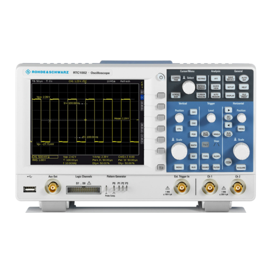
Front Panel Instrument Tour Front Panel Figure 4-1 shows the front panel of the R&S RTC1000. The function keys are grouped in functional blocks to the right of the display. Figure 4-1: Front view of the R&S RTC1000 1 = Touchscreen... -
Page 16: Input Connectors
Input Connectors BNC inputs (6, 7) The R&S RTC1000 has two channel inputs (6) to connect the input signals. The external trigger input (7) is used to control the measurement by an external sig- nal. The trigger level can be set from -5 V to 5 V. - Page 17 The instrument is not rated for any measurement category. When measur- ing in circuits with transient overvoltages of category II, III or IV circuits, make sure that no such overvoltages reach the R&S RTC1000 input. Therefore, use only probes that comply with DIN EN 61010-031. When...
-
Page 18: Other Connectors On The Front Panel
Rear Panel Figure 4-2 shows the rear panel of the R&S RTC1000 with its connectors. On the back panel of the instrument, you find Ethernet and USB interfaces. Optional interfaces are not available. - Page 19 ® Instrument Tour R&S RTC1000 Rear Panel Figure 4-2: Rear panel view of R&S RTC1000 1 = AC power supply connector and main power switch 2 = USB connector, type B 3 = LAN connector 4 = not used 5 = Kensington lock slot to secure the instrument against theft AC supply: mains connector and main power switch (1) The instrument supports a wide range power supply.
Need help?
Do you have a question about the RTC1000 and is the answer not in the manual?
Questions and answers