Table of Contents
Advertisement
Quick Links
Advertisement
Table of Contents

Related Manuals for R&S RTB2K-COM4


Summary of Contents for R&S RTB2K-COM4
- Page 1 ® R&S RTB2000 Digital Oscilloscope Getting Started (=Q@52) 1333.1605.02 ─ 03...
- Page 2 ® This manual describes the following R&S RTB2000 models: ● R&S ® RTB2002 (1333.1005K02) ● R&S ® RTB2004 (1333.1005K04) © 2017 Rohde & Schwarz GmbH & Co. KG Mühldorfstr. 15, 81671 München, Germany Phone: +49 89 41 29 - 0 Fax: +49 89 41 29 12 164 Email: info@rohde-schwarz.com...
- Page 3 Basic Safety Instructions Always read through and comply with the following safety instructions! All plants and locations of the Rohde & Schwarz group of companies make every effort to keep the safety standards of our products up to date and to offer our customers the highest possible degree of safety. Our products and the auxiliary equipment they require are designed, built and tested in accordance with the safety standards that apply in each case.
- Page 4 Basic Safety Instructions Symbol Meaning Symbol Meaning Caution ! Hot surface Alternating current (AC) Protective conductor terminal Direct/alternating current (DC/AC) To identify any terminal which is intended for connection to an external conductor for protection against electric shock in case of a fault, or the terminal of a protective earth Earth (Ground) Class II Equipment...
- Page 5 Basic Safety Instructions Operating states and operating positions The product may be operated only under the operating conditions and in the positions specified by the manufacturer, without the product's ventilation being obstructed. If the manufacturer's specifications are not observed, this can result in electric shock, fire and/or serious personal injury or death. Applicable local or national safety regulations and rules for the prevention of accidents must be observed in all work performed.
- Page 6 Basic Safety Instructions 6. The product may be operated only from TN/TT supply networks fuse-protected with max. 16 A (higher fuse only after consulting with the Rohde & Schwarz group of companies). 7. Do not insert the plug into sockets that are dusty or dirty. Insert the plug firmly and all the way into the socket provided for this purpose.
- Page 7 Basic Safety Instructions 2. Before you move or transport the product, read and observe the section titled "Transport". 3. As with all industrially manufactured goods, the use of substances that induce an allergic reaction (allergens) such as nickel cannot be generally excluded. If you develop an allergic reaction (such as a skin rash, frequent sneezing, red eyes or respiratory difficulties) when using a Rohde &...
- Page 8 Basic Safety Instructions 2. Adjustments, replacement of parts, maintenance and repair may be performed only by electrical experts authorized by Rohde & Schwarz. Only original parts may be used for replacing parts relevant to safety (e.g. power switches, power transformers, fuses). A safety test must always be performed after parts relevant to safety have been replaced (visual inspection, protective conductor test, insulation resistance measurement, leakage current measurement, functional test).
- Page 9 Instrucciones de seguridad elementales 3. If you use the product in a vehicle, it is the sole responsibility of the driver to drive the vehicle safely and properly. The manufacturer assumes no responsibility for accidents or collisions. Never use the product in a moving vehicle if doing so could distract the driver of the vehicle.
- Page 10 Customer Support Technical support – where and when you need it For quick, expert help with any Rohde & Schwarz equipment, contact one of our Customer Support Centers. A team of highly qualified engineers provides telephone support and will work with you to find a solution to your query on any aspect of the operation, programming or applications of Rohde &...
-
Page 11: Table Of Contents
® Contents R&S RTB2000 Contents 1 Preface..................5 1.1 For Your Safety..................5 1.2 Documentation Overview..............7 1.2.1 Manuals and Instrument Help..............7 1.2.2 Data Sheet and Brochure............... 8 1.2.3 Calibration Certificate................8 1.2.4 Release Notes and Open Source Acknowledgment.......8 2 Preparing for Use..............9 2.1 Unpacking and Checking the Instrument........... - Page 12 ® Contents R&S RTB2000 Getting Started 1333.1605.02 ─ 03...
-
Page 13: Preface
® Preface R&S RTB2000 For Your Safety Preface For Your Safety The R&S RTB2000 is an oscilloscope which is designed for measurements on circuits that are only indirectly connected to the mains or not connected at all. It is not rated for any measurement category. The instrument is designed for indoor use in industrial areas. - Page 14 ® Preface R&S RTB2000 For Your Safety Risk of instrument damage An unsuitable operating site or test setup can damage the instrument and connected devices. Ensure the following operating conditions before you switch on the instrument: ● Read and observe the "Basic Safety Instructions" delivered as a printed brochure with the instrument.
-
Page 15: Documentation Overview
® Preface R&S RTB2000 Documentation Overview Electromagnetic interference (EMI) may affect the measurement results. To suppress generated electromagnetic interference (EMI): ● Use suitable shielded cables of high quality. For example, use double- shielded RF and LAN cables. ● Always terminate open cable ends. ●... -
Page 16: Data Sheet And Brochure
® Preface R&S RTB2000 Documentation Overview Basic safety instructions Contains safety instructions, operating conditions and further important informa- tion. The printed document is delivered with the instrument. Instrument security procedures manual Deals with security issues when working with the R&S RTB2000 in secure areas. Service manual Describes the performance test for checking the rated specifications, module replacement and repair, firmware update, troubleshooting and fault elimination,... -
Page 17: Preparing For Use
® Preparing for Use R&S RTB2000 Unpacking and Checking the Instrument Preparing for Use Unpacking and Checking the Instrument 1. Inspect the package for damage. If the packaging material shows any signs of stress, notify the carrier who delivered the instrument. 2. -
Page 18: Positioning The Instrument
® Preparing for Use R&S RTB2000 Positioning the Instrument Positioning the Instrument The instrument is designed for use under laboratory conditions. It can be used in standalone operation on a bench top or can be installed in a rack. For standalone operation, place the instrument on a horizontal bench with even, flat surface. -
Page 19: Starting The Instrument
® Preparing for Use R&S RTB2000 Starting the Instrument Risk of instrument damage due to overheating An insufficient airflow can cause the R&S RTB2000 to overheat, which may impair the measurement results, disturb the operation, and even cause damage. ● Ensure that all fan openings are unobstructed and that the airflow perfo- rations are unimpeded. -
Page 20: Starting Up And Shutting Down
® Preparing for Use R&S RTB2000 Starting the Instrument 1. Connect the power cable to the AC power connector on the rear panel of the R&S RTB2000. 2. Connect the power cable to the socket outlet. 3. Switch the main power switch at the rear of the instrument to position I. The STANDBY key lights up. -
Page 21: Powering Off
® Preparing for Use R&S RTB2000 Starting the Instrument 2.3.3 Powering Off Powering off is required only if the instrument must be disconnected from all power supplies. 1. If the instrument is running, press the STANDBY key on the front panel to shut down the instrument. -
Page 22: Replacing The Fuses
® Preparing for Use R&S RTB2000 Replacing the Fuses Replacing the Fuses The instrument is protected by a fuse. You can find it on the rear panel between the main power switch and AC power supply. Type of fuse: Size 5x20 mm, 250V~, T2.5H (slow-blow), IEC60127-2/5 Shock hazard Before replacing a fuse, make sure that the instrument is switched off and disconnected from all power supplies. -
Page 23: Instrument Tour
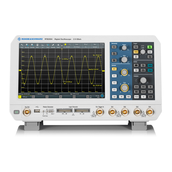
® Instrument Tour R&S RTB2000 Front Panel Instrument Tour Front Panel Figure 3-1 shows the front panel of the R&S RTB2000. The function keys are grouped in functional blocks to the right of the display. Figure 3-1: Front panel of R&S RTB2004 with 4 input channels 1 = Display 2 = Horizontal and vertical setup controls 3 = Trigger settings, action and analysis controls... -
Page 24: Input Connectors
® Instrument Tour R&S RTB2000 Front Panel 3.1.1 Input Connectors BNC inputs (4 and 5) The R&S RTB2000 has two or four channel inputs (4) to connect the input sig- nals. The external trigger input (5) is used to control the measurement by an external signal. -
Page 25: Other Connectors On The Front Panel
® Instrument Tour R&S RTB2000 Front Panel Risk of injury and instrument damage The instrument is not rated for any measurement category. When measur- ing in circuits with transient overvoltages of category II, III or IV circuits, make sure that no such overvoltages reach the R&S RTB2000 input. There- fore, use only probes that comply with DIN EN 61010-031. -
Page 26: Rear Panel
® Instrument Tour R&S RTB2000 Rear Panel PROBE COMP. (7) Probe compensation terminal to support adjustment of passive probes to the oscilloscope channel. Square wave signal for probe compensation. Ground connector for probes. USB type A (8) USB 2.0 type A interface to connect a mouse or a keyboard, or a USB flash drive for storing and reloading instrument settings and measurement data, and to update the firmware. - Page 27 ® Instrument Tour R&S RTB2000 Rear Panel Figure 3-2: Rear panel view of R&S RTB2000 1 = LAN connector 2 = USB connector, type B 3 = AC power supply connector and main power switch 4 = Kensington lock slot to secure the instrument against theft 5 = Loop for lock to secure the instrument against theft 6 = not used LAN (1)
- Page 28 X-ON Electronics Largest Supplier of Electrical and Electronic Components Click to view similar products for manufacturer: Rohde & Schwarz Other Similar products are found below : HMC8042 HZ10R HMP2020 HMP2030 HMP4040 RT-ZP03 HV512 R&S HMF2525 RTB2K-102 RTC1K-102 RTC1K-202 SMC100A/B103/B1 HA-Z211 RTB2002 (RTB2K-72) RTB2004 + RTB-B242 (RTB2K-204) RTB2004 + RTB-B242 + RTB-B1 (RTB2K- 204M) RTB2004 + RTB-B243 + RTB-B1 (RTB2K-304M) RTM3004 + RTM-B222 (RTM3K-24) RTM3002 + RTM-B223 (RTM3K-32) RTM-B222 RTM-B223 RTM-B225 RTM-B2210 RTM-B243 RTM-B2410 RTM-B1 R&S®...
Need help?
Do you have a question about the RTB2K-COM4 and is the answer not in the manual?
Questions and answers