Chapters
Table of Contents

Related Manuals for R&S RTC1K-COM2


Summary of Contents for R&S RTC1K-COM2
- Page 1 ® R&S RTC1000 Digital Oscilloscope User Manual (=S×Â2) 1335735202 Distributed by: dataTec ▪ Ferdinand-Lassalle-Str. 52 ▪ 72770 Reutlingen ▪ Tel. 07121 / 51 50 50 ▪ Fax 07121 / 51 50 10 ▪ info@datatec.de ▪ www.datatec.de...
- Page 2 This document describes the following R&S RTC1000 models: ● ® R&S RTC1000 (1335.7500K02) © 2018 Rohde & Schwarz GmbH & Co. KG Mühldorfstr. 15, 81671 München, Germany Phone: +49 89 41 29 - 0 Fax: +49 89 41 29 12 164 Email: info@rohde-schwarz.com Internet:...
-
Page 3: Table Of Contents
® Contents R&S RTC1000 Contents 1 Preface....................7 Safety Instructions......................7 Documentation Overview..................... 8 2 Getting Started..................11 Preparing for Use......................11 Instrument Tour......................15 3 Operating Basics..................19 Control Panel.......................19 Display......................... 22 Operating Concept......................23 Integrated Help......................24 Signal Display......................24 General Instrument Settings..................28 Self-Alignment......................29 Firmware Update...................... - Page 4 ® Contents R&S RTC1000 Zoom Function......................58 Marker Function......................60 XY-Display........................62 Mathematics........................ 63 Frequency Analysis (FFT)..................71 Pass/Fail Test Based on Masks................. 75 Component Test......................77 Digital Voltmeter......................81 7 Measurements..................83 Quick View........................83 Cursor Measurements....................84 Automatic Measurements..................87 8 Documenting Results................
- Page 5 ® Contents R&S RTC1000 11.5 UART/RS-232 BUS (Option R&S RTC-K2)...............135 11.6 CAN Bus (Option R&S RTC-K3)................141 11.7 LIN Bus (Option R&S RTC-K3).................147 12 Network Connections and Remote Operation.........154 12.1 LAN Connection......................154 12.2 Remote Access Using a Web Browser..............157 12.3 USB Connection......................162 12.4 Switching to Remote Control...................166...
- Page 6 ® Contents R&S RTC1000 SCPI Parameters....................... 340 Overview of Syntax Elements.................. 342 Structure of a Command Line..................343 Responses to Queries....................344 B Command Sequence and Synchronization........346 Preventing Overlapping Execution................. 346 C Status Reporting System..............348 Structure of a SCPI Status Register................ 348 Hierarchy of status registers...................
-
Page 7: Preface
® Preface R&S RTC1000 Safety Instructions 1 Preface 1.1 Safety Instructions The R&S RTC1000 digital oscilloscope is designed for measurements on circuits that are only indirectly connected to the mains or not connected at all. It is not rated for any measurement category. -
Page 8: Documentation Overview
® Preface R&S RTC1000 Documentation Overview Risk of instrument damage An unsuitable operating site or test setup can damage the instrument and connected devices. Ensure the following operating conditions before you switch on the instrument: ● Read and observe the "Basic Safety Instructions" brochure and the safety instruc- tions in the manuals. - Page 9 ® Preface R&S RTC1000 Documentation Overview Getting started manual Introduces the R&S RTC1000 and describes how to set up the product. A printed Eng- lish version is included in the delivery. User manual Contains the description of all instrument modes and functions. It also provides an introduction to remote control, a complete description of the remote control commands with programming examples, and information on maintenance and instrument interfa- ces.
- Page 10 ® Preface R&S RTC1000 Documentation Overview 1.2.4 Release Notes, Open Source Acknowledgment The release notes list new features, improvements and known issues of the current firmware version, and describe the firmware installation. The open source acknowledg- ment document provides verbatim license texts of the used open source software. It can also be read directly on the instrument.
-
Page 11: Getting Started
® Getting Started R&S RTC1000 Preparing for Use 2 Getting Started 2.1 Preparing for Use 2.1.1 Unpacking and Checking the Instrument 1. Inspect the package for damage. If the packaging material shows any signs of stress, notify the carrier who delivered the instrument. - Page 12 ® Getting Started R&S RTC1000 Preparing for Use The instrument can be installed in a 19" rack mount using a rack mount kit. The order number of the rack mount kit is given in the data sheet. The installation instructions are part of the rack mount kit.
- Page 13 ® Getting Started R&S RTC1000 Preparing for Use The nominal ranges are: ● 100 V to 240 V AC at 50 Hz to 60 Hz, or 100 V to 120 V at 400 Hz ● max. 25 W Risk of injury Connect the instrument only to an outlet that has a ground contact.
- Page 14 ® Getting Started R&S RTC1000 Preparing for Use All current settings are saved, and the software shuts down. Now it is safe to power off the instrument. 2.1.3.3 Powering Off Powering off is required only if the instrument must be disconnected from all power supplies.
-
Page 15: Instrument Tour
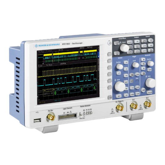
® Getting Started R&S RTC1000 Instrument Tour 2.2 Instrument Tour 2.2.1 Front Panel Figure 2-1 shows the front panel of the R&S RTC1000. The function keys are grouped in functional blocks to the right of the display. Figure 2-1: Front view of the R&S RTC1000 1 = Display 2 = Softkeys and menu 3 = [ON/OFF] key... - Page 16 ® Getting Started R&S RTC1000 Instrument Tour 2.2.1.1 Input Connectors BNC inputs (6, 7) The R&S RTC1000 has two channel inputs (6) to connect the input signals. The exter- nal trigger input (7) is used to control the measurement by an external signal. The trig- ger level can be set from -5 V to 5 V.
- Page 17 ® Getting Started R&S RTC1000 Instrument Tour Logic probe (9) The connector for logic channels can be used if the Mixed Signal Option R&S RTC-B1 is installed. The option provides a logical probe with 8 digital channels (D0 to D7). The maximum input voltage is 40 V (peak) at 100 kΩ...
- Page 18 ® Getting Started R&S RTC1000 Instrument Tour On the back panel of the instrument, you find Ethernet and USB interfaces. Optional interfaces are not available. Figure 2-2: Rear panel view of R&S RTC1000 1 = AC power supply connector and main power switch 2 = USB connector, type B 3 = LAN connector 4 = not used...
-
Page 19: Operating Basics
® Operating Basics R&S RTC1000 Control Panel 3 Operating Basics 3.1 Control Panel The controls on the front panel allow access to all basic functions. Advanced settings are easily accessible using the menu structure and gray softkeys. The [ON/OFF] but- ton is clearly set apart by its design. - Page 20 ® Operating Basics R&S RTC1000 Control Panel 3.1.3 General Section [SAVE/RECALL] Opens a menu to load and save instrument settings, reference signals, waveforms, screenshots of the display, and formularies. In the menu, you can also assign the function of the [FILE/ PRINT] key.
- Page 21 ® Operating Basics R&S RTC1000 Control Panel [MENU] Opens the advanced menu for the selected waveform, bus or pod. [UTIL] Opens a menu with more applications: digital voltmeter, function and pattern generator (requires option R&S RTC-B6), compo- nent tester, and trigger counter. 3.1.5 Trigger Section The Trigger section provides all controls to adjust the trigger.
-
Page 22: Display
® Operating Basics R&S RTC1000 Display [Left Arrow ], [Right Arrow] / Set and deletes markers, and navigate markers. [SET/CLR] If no markers are set, the arrow keys move the trigger position by 5 division to the left or right. [SET/CLR] resets the value to the time reference point. -
Page 23: Operating Concept
® Operating Basics R&S RTC1000 Operating Concept 1 = Horizontal scale (time base), in s/div 2 = Trigger position 3 = Time reference, zero point of the time axis 4 = Trigger settings: source, level, type, and filter conditions 5 = Sample rate 6 = Acquisition mode 7 = Vertical scrollbar, visible if virtual screen with 20 vertical divisions is on 8 = Short menu with most important settings of the selected channel... -
Page 24: Integrated Help
® Operating Basics R&S RTC1000 Signal Display ● Depending on the requirements, the [Universal] knob in the Cursor/Menu section either selects a value, or navigates through menus. The COARSE/FINE key tog- gles between fine and coarse resolution of the [Universal] knob. ●... - Page 25 ® Operating Basics R&S RTC1000 Signal Display Figure 3-1: Display menu, page 1/2 (left) and page 2/2 (right) VIRTUAL SCREEN Chapter 3.5.2, "Virtual Screen", on page 26. DOTS ONLY If enabled, only the acquired data points are shown. The data points are not connected by lines.
- Page 26 ® Operating Basics R&S RTC1000 Signal Display "POSITION" If activated and the vertical position is changed, the value of the verti- cal position is shown at the zero line. "ACQ.STA- If activated, the information on the acquisition status is shown. In nor- mal trigger mode, if the trigger condition is fulfilled, the information TUS"...
- Page 27 ® Operating Basics R&S RTC1000 Signal Display Figure 3-2: Drawing of the virtual screen area 3.5.3 Signal Intensity and Persistence To change the intensity of the waveforms: 1. Press the [INTENS/PERSIST] key in the Cursor/Menu section until it lights up in white.
-
Page 28: General Instrument Settings
® Operating Basics R&S RTC1000 General Instrument Settings Figure 3-3: Persistence function "MANUAL" You can set a duration of 50 ms to infinite by using the [universal] knob or the [KEYPAD] key. If a finite duration is selected, new signals are written on top of one another. -
Page 29: Self-Alignment
® Operating Basics R&S RTC1000 Self-Alignment "LANGUAGE" Selects the language for user interface and help. "SELF ALIGNMENT" The instrument adjusts vertical accuracy, time base and several trigger settings and saves the identified correction data internally. See also: Chapter 3.7, "Self-Alignment", on page 29. -
Page 30: Firmware Update
® Operating Basics R&S RTC1000 Firmware Update 3. Press "START". The procedure can take up to 16 minutes. Figure 3-4: Self-alignment successful If an error occurs during the self-alignment although it has been carried out as descri- bed, export the .log file in the "SELF ALIGNMENT" menu and send it to customer- support@rohde-schwarz.com. -
Page 31: Options
® Operating Basics R&S RTC1000 Options 5. Select "UPDATE". A window with information about the installed firmware and front controller firmware is shown. 6. Select "FIRMWARE". The information on the new firmware is added in the window. If you have no newer firmware than the installed one, a message appears. - Page 32 ® Operating Basics R&S RTC1000 Options 6. If you received a key in written form: a) Select "INPUT KEY MANUALLY". b) Enter the key. 7. If you received a key in digital form as a file: a) Select "READ KEYS FROM LICENSE FILE". b) Select the "Front"...
- Page 33 ® Operating Basics R&S RTC1000 Options d) Select "LOAD". 8. If you want to activate several options, repeat step 6 or 7 for each option. 9. Restart the instrument. User Manual 1335.7352.02 ─ 04...
-
Page 34: Waveform Setup
® Waveform Setup R&S RTC1000 Vertical Setup 4 Waveform Setup 4.1 Vertical Setup The most important vertical settings are permanently available for adjustment: ● Channel keys to switch on or off and to select a channel ● Rotary knobs to adjust vertical scale and position ●... - Page 35 ® Waveform Setup R&S RTC1000 Vertical Setup 1. Select the channel using its [CH] key. 2. Press the [MENU] key in the Vertical section. Page 1 of the menu shows the settings of the short menu, page 2 provides further set- tings.
- Page 36 ® Waveform Setup R&S RTC1000 Vertical Setup BANDWIDTH (BWL) Inserts an analog 20 MHz low-pass filter to the signal path. Higher frequencies are removed to reduce noise. Limited bandwidth is indicated by "B " in the waveform label. INVERT (INV) Turns the inversion of the signal amplitude on or off.
- Page 37 ® Waveform Setup R&S RTC1000 Vertical Setup LABEL The "LABEL" key on page 2/2 opens the label menu to define a name label for the selected waveform. The label is shown and printed at the waveform on the right edge of the display.
- Page 38 ® Waveform Setup R&S RTC1000 Vertical Setup Make sure to align passive probes before their first use, after an extended measure- ment break, or when switching instruments or channels. Two connector pins for compensation are located at the front panel. The left pin is on ground level.
-
Page 39: Horizontal Setup
® Waveform Setup R&S RTC1000 Horizontal Setup To perform probe compensation manually 1. Press the [UTIL] menu in the Vertical section. 2. Select the "PATTERN GEN." softkey. 3. Select "SQUARE WAVE" (see Chapter 10.2.1, "Square Wave", on page 115). 4. Use the compensation trimmer of the probe to get optimum square wave response. For details, refer to the documentation of your probe. -
Page 40: Acquisition Setup
® Waveform Setup R&S RTC1000 Acquisition Setup – Set the trigger position to minimum or maximum value: "MINIMUM" or "MAXIMUM". – Set the trigger position to zero. 3. To set the time reference point: a) Press the [MENU] key. b) Press the "TIME REF." softkey. c) Use the universal knob in the Cursour/Menu section to adjust the value. - Page 41 ® Waveform Setup R&S RTC1000 Acquisition Setup ROLL Enables the roll mode. The roll mode displays the untriggered, continuous signal. The roll mode moves the captured input data on the display from the right to the left. The instrument shows the waveform immediately, without waiting for the complete acquisition of the waveform record.
- Page 42 ® Waveform Setup R&S RTC1000 Acquisition Setup ● No serial or parallel bus is active. If "PEAK DETECT" is set to "Auto", the instrument selects the best peak detection mode depending on the time base and sampling rate. The minimum and the maximum of each sampling interval are recorded as data pairs, and the other samples are discar- ded.
- Page 43 ® Waveform Setup R&S RTC1000 Acquisition Setup The memory depth corresponds to the displayed time window (time base x 10 grid sec- tions in horizontal direction) multiplied by the current sampling rate. The minimum value is determined by the maximum sampling rate and the maximum signal repeat rate of the oscilloscope.
- Page 44 ® Waveform Setup R&S RTC1000 Acquisition Setup Figure 4-5: Example figure of AM modulated signal with max. sampling rate AUTOMATIC "AUTOMATIC" is the default setting and offers the best compromise between maxi- mum repeat rate and maximum sampling rate (selection of memory depth). Each col- umn in the signal window displays up to 10 captured data values.
- Page 45 ® Waveform Setup R&S RTC1000 Acquisition Setup Figure 4-6: Example figure of AM modulated signal with automatic setting 4.3.3.1 Comparison of Record Modes In all record modes, the sampling rate used to write to the acquisition memory is the same. In "STOP" mode, it is also possible to change menu items. Changing the record mode does not impact the current memory depth but the amount of displayed data is adjusted.
- Page 46 ® Waveform Setup R&S RTC1000 Acquisition Setup Table 4-1: Advantages and disadvantages of record modes Setting Advantages Disadvantages Application ● ● ● Maximum Many captures in one image High aliasing risk Search for rare events ● ● ● Rare events can be detected more Low accuracy of details Displaying modulated waveform...
-
Page 47: Trigger
® Trigger R&S RTC1000 Setting Up the Trigger 5 Trigger Triggering means to capture the interesting part of the relevant waveforms. Choosing the right trigger type and configuring all trigger settings correctly allows you to detect various incidents in signals. A trigger occurs if the trigger conditions are fulfilled. -
Page 48: General Trigger Settings
® Trigger R&S RTC1000 General Trigger Settings 5.2 General Trigger Settings The keys in the Trigger section provide all functions to set up the trigger. [AUTO/NORM] trigger modes Sets the trigger mode. The Trigg'd LED lights up if the instrument found a trigger event. "AUTO"... -
Page 49: Edge Trigger
® Trigger R&S RTC1000 Edge Trigger ● An analog channel. ● A digital channel if option R&S RTC-B1 is installed. ● The power supply frequency ("AC LINE"). The trigger signal is extracted internally from the power supply. ● An external signal that is connected to the external trigger input. Select the cou- pling of the trigger signal: AC or DC. - Page 50 ® Trigger R&S RTC1000 Edge Trigger AUTO LEVEL Automatic filter setting (default setting). The trigger signal is coupled through a 5 Hz high-pass filter which suppresses the DC portion of the trigger signal. With a changing DC portion, the trigger level remains at the set point in the AC signal.
-
Page 51: Pulse Trigger
® Trigger R&S RTC1000 Pulse Trigger 5.4 Pulse Trigger The pulse trigger finds specific pulse widths of positive or negative pulses or on pulse width ranges. If a pulse on the trigger source fulfills the trigger condition, the oscillo- scope triggers on the trailing slope. For a positive pulse, it triggers on the falling slope, and for a negative pulse on a rising slope. -
Page 52: Logic Trigger
® Trigger R&S RTC1000 Logic Trigger POLARITY Sets the polarity, alternatively to the [SLOPE] key. For positive pulses, you define the width from rising to falling slopes, and accordingly for negative pulses from falling to rising slopes. Consequently, the trigger always occurs on the second slope of the pulse. - Page 53 ® Trigger R&S RTC1000 Logic Trigger 3. Turn the Universal knob to select the "LOGIC CHANNEL" for which you want to set the logic state. 4. Press "STATE" repeatedly until the required state is selected. 5. Repeat steps 3 and 4 for each channel of the pattern. 6.
- Page 54 ® Trigger R&S RTC1000 Logic Trigger TRIGGER ON Selects whether the trigger is generated at the beginning ("TRUE") or the end of the fulfilled logic condition ("FALSE"). 5.5.2 Time Limitation To set a time limitation for the pattern, you have several possibilities. They are similar to the setting of a pulse width, see Chapter 5.4, "Pulse Trigger",...
-
Page 55: Video Trigger
® Trigger R&S RTC1000 Video Trigger Triggers if the pattern condition is fulfilled for a duration shorter than time t1 t1", or longer than time t2. These settings are an alternative setting to the definition with "Width =" and variation. The time values are interdependent and adjusted accordingly. -
Page 56: Trigger Out Pulses
® Trigger R&S RTC1000 External Trigger Input ● HDTV 720p Progressive ● HDTV 1080p Progressive ● HDTV 1080i Interlaced SIGNAL Selects the polarity of the sync pulse (positive or negative). With positive video modu- lation, when the highest brightness is represented by the maximum signal voltage in the image ), the synchronization pulses are negative. - Page 57 ® Trigger R&S RTC1000 External Trigger Input Figure 5-3: External trigger signal User Manual 1335.7352.02 ─ 04...
-
Page 58: Analysis
® Analysis R&S RTC1000 Zoom Function 6 Analysis The R&S RTC1000 features various functions to analyze waveforms on the display. ● Zoom Function......................58 ● Marker Function...................... 60 ● XY-Display.......................62 ● Mathematics......................63 ● Frequency Analysis (FFT)..................71 ● Pass/Fail Test Based on Masks................ - Page 59 ® Analysis R&S RTC1000 Zoom Function μ s per division, the zoomed time window is 12 ms Figure 6-1: Zoom window with 100 Above the zoom window, you see the zoom time base "Z" (zoom factor), which deter- mines the width of the zoom area (12 divisions x scaling per division). "Tz" indicates the zoom time and determines the position of the zoom area.
-
Page 60: Marker Function
® Analysis R&S RTC1000 Marker Function MAL" always stores more samples in the memory than what can be shown in the dis- play. That explains that you can zoom in the signal using the memory data. The values in the Y axis (amplitude) can be scaled also in roll mode because they apply to a speci- fied axis. - Page 61 ® Analysis R&S RTC1000 Marker Function Figure 6-2: Marker in zoom mode 1. To toggle markers, use the [ARROW] keys. The selected marker is set to the cen- ter of the screen. Thus, you can quickly compare marked signal sections in zoom mode. 2.
-
Page 62: Xy-Display
® Analysis R&S RTC1000 XY-Display Figure 6-3: Marker menu TRIGGER TIME SET TO ZERO Sets the trigger time to 0 s. CLEAR ALL MARKER Deletes all defined time markers. 6.3 XY-Display The XY-display combines the voltage levels of two waveforms in one diagram. The voltage level of the first signal is displayed in y-direction, and the voltage level of a sec- ond signal in x-direction. -
Page 63: Mathematics
® Analysis R&S RTC1000 Mathematics The display shows one large and two small diagrams. The large diagram shows the XY-display. The small diagrams show the sources for X and Y, the normal sig- nal display as Y vs. time. 6.4 Mathematics Math waveforms are calculated waveforms. - Page 64 ® Analysis R&S RTC1000 Mathematics b) Turn the [Scale] knob in the Vertical section. 6.4.1 Quick Mathematics (QM) Quick mathematics create one math waveform with basic mathematical operators on analog channels 1 and 2. 1. Press the [MATH] key in the Vertical section. The short math menu opens.
- Page 65 ® Analysis R&S RTC1000 Mathematics Addition Subtraction Multiplication Division 6.4.2 Advanced Mathematics Using the advanced mathematics (MA), you can create up to five formulary sets. Each formulary set can include up to five equations. Equations provide more operators and more sources than the Quick Mathematics. Formulary sets can be saved and loaded for further use.
- Page 66 ® Analysis R&S RTC1000 Mathematics Figure 6-6: Mathematics menu 4. To select a formulary set, turn the Universal knob in the Cursor/Menu section. 5. To open the equation menu, press "EDIT FORMULARY". 6. To select an equation, turn the Universal knob in the Cursor/Menu section. 7.
- Page 67 ® Analysis R&S RTC1000 Mathematics Figure 6-7: Display settings for equations 3. To activate the equation, press "VISIBLE" until "On" is selected. An active visible equation is marked by an eye symbol in the formula editor, and it is listed in the short menu. 4.
- Page 68 ® Analysis R&S RTC1000 Mathematics Figure 6-8: Equation parameters (edit equation) 7. Press OPERATOR. Turn the Universal knob to select the operator. 8. To select the operands, press the "OPERAND" softkeys. For each equation, the input channels CH1, CH2 and a constant are available as operands (sources).
- Page 69 ® Analysis R&S RTC1000 Mathematics Figure 6-9: Customize a constant 6.4.2.3 To Save and Load a Formulary Set If all equations of a formulary set are defined, you can save the set. 1. Navigate to the "MATHEMATICS" menu. 2. Press "SAVE". 3.
- Page 70 ® Analysis R&S RTC1000 Mathematics 3. Select "EDIT" = "Display". 4. Assign the unit "A" (Ampere) to the equation by pressing "UNIT". 5. Press "LABEL" and enter CURRENT. 6. Select "EDIT" = "Parameter". 7. Select "CH1" as "OPERAND 1" and "Const." as "OPERAND 2". 8.
-
Page 71: Frequency Analysis (Fft)
® Analysis R&S RTC1000 Frequency Analysis (FFT) To define the ENERGY equation 1. Add a third equation "MA3" to formulary set 1. 2. Select "EDIT" = "Parameter". 3. Choose "Integral" as "OPERATOR" and "POWER" as "OPERATOR 1". Figure 6-11: Definition of the power equation 4. - Page 72 ® Analysis R&S RTC1000 Frequency Analysis (FFT) ► To start the FFT, press the [FFT] key in the Analysis section Figure 6-12: FFT In FFT mode, the screen is divided into two grids: ● The upper grid shows the voltage vs time waveform. The time domain settings are shown above the grid, on the left.
- Page 73 ® Analysis R&S RTC1000 Frequency Analysis (FFT) Active settings are highlighted in white, inactive settings are gray. The FFT menu provides further settings. MODE Sets the display type: "REFRESH" Calculates and displays the FFT without additional evaluation or edit- ing of the captured data. The new input data is captured, displayed and overwrites previously stored and displayed values.
- Page 74 ® Analysis R&S RTC1000 Frequency Analysis (FFT) "Hamming" The Hamming window is bell shaped. Its value is not zero at the bor- ders of the measuring interval. Thus, the noise level inside the spec- trum is higher than Hanning or Blackman, but smaller than the rectan- gular window.
-
Page 75: Pass/Fail Test Based On Masks
® Analysis R&S RTC1000 Pass/Fail Test Based on Masks 6.6 Pass/Fail Test Based on Masks The Pass/Fail test evaluates whether a signal is located within defined limits. The limits are set by a mask. If the signal exceeds the mask limits, an error (fail) is counted. The number of errors, the number of successful acquisitions, and the total acquisition count are displayed at the bottom of the display. - Page 76 ® Analysis R&S RTC1000 Pass/Fail Test Based on Masks 3. To shift the mask vertically, or to enlarge it, press "Y-POSITION" and "STRETCH Y", and use the Universal knob 4. To set the tolerance for the mask test, press "WIDTH Y" and "WIDTH X". Use the Universal knob or the [KEYPAD] to enter values with a resolution of 1/100 division.
-
Page 77: Component Test
® Analysis R&S RTC1000 Component Test To perform a pass/fail test 1. In the "PASS/FAIL" menu, press "TEST Run/Stop" to start the test. Below the grid, you see the total number and the total duration of the tests in white. The number of successful tests and their percentage is displayed in green, and the number of failures and their percentage are displayed in red. - Page 78 ® Analysis R&S RTC1000 Component Test Risk of electric shock Make sure to discharge capacitors before test. If components are tested which are located in circuits or instruments, make sure to set the circuits or instruments currentless. If they are operated from the mains, also pull out the mains plug of the test object.
- Page 79 ® Analysis R&S RTC1000 Component Test form factor of the ellipse are determined by the apparent impedance at 50 Hz (resp. 200 Hz). ● An ellipse with horizontal long axis indicates a high impedance (small capacitance or large inductance). ● An ellipse with vertical long axis indicates a low impedance (large capacitance or small inductance).
- Page 80 ® Analysis R&S RTC1000 Component Test Figure 6-16: Exmaple results of component tests User Manual 1335.7352.02 ─ 04...
-
Page 81: Digital Voltmeter
® Analysis R&S RTC1000 Digital Voltmeter Risk of instrument damage Observe the necessary precautions when handling MOS components. They can be destroyed by static charges or tribo electricity. 6.7.1 In-circuit Tests In-circuit tests are possible but often do not deliver clear results. By paralleling of real or complex impedances –... - Page 82 ® Analysis R&S RTC1000 Digital Voltmeter a) Select the primary measurement for channel 1 and channel 2. b) Press"SECONDARY" for the corresponding channel to select the secondary measurement. The following primary and secondary measurements are available: ● OFF: Measurement off ●...
-
Page 83: Measurements
® Measurements R&S RTC1000 Quick View 7 Measurements There are several methods to measure on signals: quick view, cursor measurements and automatic measurements. All measurements are stored in a buffer memory that is larger than the display memory. 7.1 Quick View The quick view function provides a quick overview of the typical signal characteristics. -
Page 84: Cursor Measurements
® Measurements R&S RTC1000 Cursor Measurements ● Fall time (t The following measurement values are displayed at the bottom of the screen: ● RMS value ● Peak to peak voltage ● Amplitude ● Pos. pulse width ● Pos. duty ratio ●... - Page 85 ® Measurements R&S RTC1000 Cursor Measurements Figure 7-1: Cursor measurement menu MEASURE TYPE Defines the measurement type. To learn about the individual types, see Chapter 7.2.2, "Measurement Types", on page 86. AUTOM. SOURCE, SOURCE If "AUTOM. SOURCE" is activated ("On"), the selected channel is used as source for the measurement.
- Page 86 ® Measurements R&S RTC1000 Cursor Measurements If deactivated, the cursors stay in position on the screen if the waveform is scaled, and the measured value changes. 7.2.2 Measurement Types The following cursor measurement types are available: Voltage "Voltage" provides two cursors and measures three voltages. The values V1 and V2 correspond to the voltage between the zero base line of the selected signal and the current position of the first or second cursor.
-
Page 87: Automatic Measurements
® Measurements R&S RTC1000 Automatic Measurements RMS, Mean, σ This measurement type provides two cursors and measures the effective value (RMS – root mean square), the mean value and the standard deviation within the interval set by both cursors. Duty Ratio "Duty Ratio"... - Page 88 ® Measurements R&S RTC1000 Automatic Measurements If "n/a" is displayed, the measurement is not applicable to the signal. For instance, if you measure a voltage on a POD, no result is displayed because only logic states with- out voltage reference are displayed. If "?"...
- Page 89 ® Measurements R&S RTC1000 Automatic Measurements SOURCE Selects the waveform to be measured. The list only includes displayed channels. Pos- sible sources are analog, digital and mathematical channels. CLEAR ALL Switches off the activated automatic measurements. 7.3.2 Automatic Measurement Types The following types of automatic measurements are available: Mean Value Measures the mean value of the signal amplitude (Mean).
- Page 90 ® Measurements R&S RTC1000 Automatic Measurements Period "Period" measures the duration of the signal period T. The period identifies the duration between two equal values of one periodically repeated signal. Amplitude Measures the amplitude of a square wave signal (V ).
- Page 91 ® Measurements R&S RTC1000 Automatic Measurements Pulse Width – "Pulse Width –" measures the width of the negative pulse. A negative pulse consists of a falling slope followed by a rising slope. The measurement identifies the two slopes and calculates the pulse width from their time difference (t). The measurement requires at least one complete period of a triggered signal.
- Page 92 ® Measurements R&S RTC1000 Automatic Measurements Phase Measures the phase between two slopes of two channels in the display (Phs). It meas- ures the relation of the time delay between the sources to the signal period of the mea- surement source. The instrument searches for the slope of the measurement source that is closest to the time reference.
- Page 93 ® Measurements R&S RTC1000 Automatic Measurements Trigger Period "Trigger Period" measures the duration of periods of the trigger signal T with a hard- ware counter. The source for the measurement is the current trigger source. User Manual 1335.7352.02 ─ 04...
-
Page 94: Documenting Results
® Documenting Results R&S RTC1000 Saving and Loading Instrument Settings 8 Documenting Results The R&S RTC1000 can store various data to files for further usage, analysis and reporting. Waveform data and screenshots, which are intended for analysis outside the oscillo- scope, are always saved to a USB flash drive. - Page 95 ® Documenting Results R&S RTC1000 Saving and Loading Instrument Settings can be helpful to refer to the configuration settings of a particular measurement when analyzing the results. Therefore, you can easily save the complete measurement con- figuration. The softkey "DEVICE SETTINGS" allows you to save current instrument settings, load saved settings and import or export instrument settings to USB flash drive.
- Page 96 ® Documenting Results R&S RTC1000 Saving and Loading Instrument Settings Figure 8-2: SAVE menu for instrument settings 2. Press the "STORAGE" softkey. The file manager window opens. 3. Select the location: internal memory or front USB connection, where you want to save the instrument settings.
-
Page 97: Reference Waveforms
® Documenting Results R&S RTC1000 Reference Waveforms 3. Use the softkey "SORT ENTRIES" to sort the settings files by name, type, size or date. 4. Use the [Universal] knob to select the settings file. 5. Press "LOAD". The settings are read an applied on the instrument. 6. - Page 98 ® Documenting Results R&S RTC1000 Reference Waveforms Figure 8-3: Menu for references 3. To create and display a reference waveform: a) Press "SOURCE". Use the [Universal] knob to select the waveform that you want to store as reference. You can select from active channels, other reference waveforms, pod and mathematical waveforms.
-
Page 99: Waveforms (Traces)
® Documenting Results R&S RTC1000 Waveforms (Traces) b) Press "DISPLAY". Use the [Universal] knob to select the target reference wave- form. c) Press "LOAD". d) In the file manager menu, select the storage, the directory, and the file. e) Press "LOAD" to read and display the reference. To import or export references 1. - Page 100 ® Documenting Results R&S RTC1000 Waveforms (Traces) Figure 8-4: Trace storage menu 3. To select the target directory, press "STORAGE". a) Use the softkey "SORT ENTRIES" to sort the files by name, type, size or date. b) Change, create or delete directories. c) Select the target directory.
- Page 101 ® Documenting Results R&S RTC1000 Waveforms (Traces) The file is written according to the settings. 8.3.1 Waveform File Formats Data of all waveforms is saved as a succession of values or pairs of values. Pairs of values are written as two consecutive single values. Depending on the file format, only amplitude values are stored, or the amplitude values are stored together with their time value, or frequency value in FFT mode.
- Page 102 ® Documenting Results R&S RTC1000 Waveforms (Traces) 3.051758E+02,-1.19854E+01 4.577637E+02,-1.56854E+01 Import of CSV files: If you import a CSV file as reference waveform from a USB flash drive to the instrument, the import converts the data to TRF format. The instrument reads the first and the last time value and calculates the total time of the waveform, and it counts the number of values.
-
Page 103: Screenshots
® Documenting Results R&S RTC1000 Screenshots The data can be loaded as reference waveform for further use on the instrument. It is not intended for analysis outside the R&S RTC1000. 8.4 Screenshots You can create a screenshot of the current display of your waveforms and measure- ment results and save it to a file, or print it on a connected printer. - Page 104 ® Documenting Results R&S RTC1000 Screenshots "PNG" Portable Network Graphic is a graphic format with lossless data com- pression. COLOR MODE Selects the color settings for the screenshot. "Grayscale" Colors are converted to gray scales when the waveform is stored. "Color"...
-
Page 105: Quick Access With File/Print Key
® Documenting Results R&S RTC1000 Quick Access with FILE/PRINT Key 3. Press "PAPER FORMAT". Select the required format using the [Universal] knob. 4. Press "COLOR MODE". 5. Select the colors, see "COLOR MODE" on page 104. 6. To select the printer language that is used by your printer, press "COMMAND SET". - Page 106 ® Documenting Results R&S RTC1000 Quick Access with FILE/PRINT Key ● "SCREENSHOTS": Stores screenshots ● "SCREEN & SETUP": Stores screenshots and settings ● "PRINT": Prints directly to a connected printer Figure 8-6: Definition of FILE/PRINT key 4. Configure the settings for the selected action as described in the previous sections. If you press the [FILE/PRINT] key, the selected function is performed.
-
Page 107: Mixed Signal Operation (Option R&S Rtc-B1)
® Mixed Signal Operation (Option R&S RTC-B1) R&S RTC1000 Using Logic Channels 9 Mixed Signal Operation (Option R&S RTC- The R&S RTC1000 has a connector for the R&S RT-ZL03 logic probe to add 8 digital logic inputs. To use the logic analysis, you need the option R&S RTC-B1. The logic probe comes with the option. - Page 108 ® Mixed Signal Operation (Option R&S RTC-B1) R&S RTC1000 Using Logic Channels ● "To label the individual bits of the logic probe" on page 109 To set the threshold for logic states 1. Press the [POD] key. 2. Press the [MENU] key in the Vertical section. 3.
- Page 109 ® Mixed Signal Operation (Option R&S RTC-B1) R&S RTC1000 Using Logic Channels 2. Choose the Y-position and the size of the logic channel display as you do for the analog channels: a) Press the softkey "0/7" in the short menu until it highlights blue. b) To adjust size and position of all logic channels on the screen, use the vertical [Position] and [Scale] knobs.
-
Page 110: Logic Trigger For Digital Input
® Mixed Signal Operation (Option R&S RTC-B1) R&S RTC1000 Cursor Measurements for Logic Channels Figure 9-3: Bit DAC signal change 9.2 Logic Trigger for Digital Input To trigger on logic channels, you can use the logic trigger, see Chapter 5.5, "Logic Trig- ger", on page 52. -
Page 111: Automatic Measurements For Logic Channels
® Mixed Signal Operation (Option R&S RTC-B1) R&S RTC1000 Using Logic Channels in Buses For logic channels, the logic value of the selected POD is measured at the cursor position and shown in hexadecimal and decimal format. 9.4 Automatic Measurements for Logic Channels If the logic channels active, you can use the automatic measurement functions to determine several parameters ([AUTO MEASURE] key). - Page 112 ® Mixed Signal Operation (Option R&S RTC-B1) R&S RTC1000 Using Logic Channels in Buses To configure the parallel or parallel bus 1. In the "BUS" menu, press "CONFIGURATION". 2. Press "BUS WIDTH". Use the [Universal] knob to select the number of bit lines. 3.
- Page 113 ® Mixed Signal Operation (Option R&S RTC-B1) R&S RTC1000 Using Logic Channels in Buses Table 9-1: Content of the parallel bus table Column Description "Start Time" Time of frame start in relation to the trigger point "Data" Values of the data bytes To trigger on parallel buses, you can use the logic trigger (see Chapter 5.5, "Logic Trig- ger",...
-
Page 114: Signal Generation (Option R&S Rtc-B6)
® Signal Generation (Option R&S RTC-B6) R&S RTC1000 Function Generator 10 Signal Generation (Option R&S RTC-B6) The signal generation option R&S RTC-B6 provides a function generator and a pattern generator. You can find the generator settings in the [UTIL] menu. To load a predefined function or pattern The instrument provides a predefined pattern files for the important functions and pat- terns. -
Page 115: Pattern Generator
® Signal Generation (Option R&S RTC-B6) R&S RTC1000 Pattern Generator AMPLITUDE Selects the signal amplitude. OFFSET Selects a DC offset. 10.2 Pattern Generator The pattern generator outputs parallel patterns on the four pins P0 to P3 on the front panel of the instrument. It is based on a 2048-bit wide memory (samples). The pattern can be issued cyclically or individually. - Page 116 ® Signal Generation (Option R&S RTC-B6) R&S RTC1000 Pattern Generator Table 10-2: Counter frequencies Frequency f/16 10.2.3 Arbitrary You can define a 4 bit wide and a 2048 sample deep arbitrary pattern. The created pat- tern can be stored and loaded. If a pattern is generated when you call the arbitrary function, the pattern is retained.
- Page 117 ® Signal Generation (Option R&S RTC-B6) R&S RTC1000 Pattern Generator Figure 10-2: Arbitrary pattern setup "PATTERN Determines the pattern depth. LENGTH" "INDEX" Selects the sample, for which the value is set. The selected sample is marked in the information box by a blue line. Around the index, ±8 bits are displayed.
- Page 118 ® Signal Generation (Option R&S RTC-B6) R&S RTC1000 Pattern Generator "N-CYCLE" Defines how often a pattern is issued if "BURST" = "On". If the burst is disabled, the setting is not available. SAVE/LOAD Saves the created pattern, or loads and apllies a previously saved pattern. The pattern can be stored internally or externally on a connected USB flash drive.
- Page 119 ® Signal Generation (Option R&S RTC-B6) R&S RTC1000 Pattern Generator Table 10-3: Pin assignment of the bus signal source Signal P0 / Clock MOSI MISO Chip Select Data SDA no signal no signal Clock SCL UART no signal no signal CAN L no signal no signal...
-
Page 120: Serial Bus Analysis
® Serial Bus Analysis R&S RTC1000 Bus Configuration 11 Serial Bus Analysis To trigger and decode serial buses on the digital channels and on the analog inputs, the following options are available: ● R&S RTC-K1: I C and SPI buses ●... - Page 121 ® Serial Bus Analysis R&S RTC1000 Bus Configuration ● "SSPI" (available with R&S RTC-K1) ● "SPI" (available with R&S RTC-K1) ● "I C" (available with R&S RTC-K1) ● "UART" (available with R&S RTC-K2) ● "CAN" (available with R&S RTC-K3) ● "LIN"...
-
Page 122: Bus Table: Decode Results
® Serial Bus Analysis R&S RTC1000 Bus Table: Decode Results 3. Press "BITS" to activate or deactivate the display of individual bit lines above the table display. To enter a bus name 1. Press "LABEL". 2. To switch on or off the label display, press "LABEL". 3. - Page 123 ® Serial Bus Analysis R&S RTC1000 Bus Table: Decode Results Figure 11-2: Example of I2C BUS with bus table To export the decode results 1. Stop the acquisition. 2. In the "BUS TABLE" menu, press "SAVE". 3. Connect a USB flash drive to the instrument. 4.
-
Page 124: I 2 C Bus (Option R&S Rtc-K1)
® Serial Bus Analysis R&S RTC1000 C Bus (Option R&S RTC-K1) BUS TABLE Activates or deactivates the list view. Generally, a complete message (frame) of a pro- tocol is displayed in a row. The columns contain time information, data, and address message if applicable. - Page 125 ® Serial Bus Analysis R&S RTC1000 C Bus (Option R&S RTC-K1) Figure 11-3: I2C 7-bit address The format of a simple I C message (frame) with an address length of 7 bit has the following structure: ● Start condition: falling slope on SDA (serial data), while SCL (serial clock) is high ●...
- Page 126 ® Serial Bus Analysis R&S RTC1000 C Bus (Option R&S RTC-K1) To configure the I C bus 1. In the "BUS" menu, press "CONFIGURATION". 2. To select the source channel, press "CLOCK SCL". Use the [Universal] knob to select. 3. To define the data channel, press "DATA SDA" and use the [universal] knob. 4.
- Page 127 ® Serial Bus Analysis R&S RTC1000 C Bus (Option R&S RTC-K1) The bus is only available if it is configured correctly. 5. Press the [FILTER] key in the Trigger section to list all available I C trigger condi- tions. 6. Configure the trigger condition. Possible conditions are described below. 7.
- Page 128 ® Serial Bus Analysis R&S RTC1000 C Bus (Option R&S RTC-K1) Figure 11-5: Read/Write trigger menu "MASTER" Toggles the trigger condition between read and write access. The 8th bit of the first data unit (depending on the address length) is used to distinguish between read and write access.
- Page 129 ® Serial Bus Analysis R&S RTC1000 C Bus (Option R&S RTC-K1) BYTE OFFSET ← DATA Defines the number of bytes to be ignored before the relevant bytes of the trigger con- dition. Usually, the byte offset is zero if the trigger is to occur on the maximum first 24 bits after the address.
-
Page 130: Spi / Sspi Bus (Option R&S Rtc-K1)
® Serial Bus Analysis R&S RTC1000 SPI / SSPI BUS (Option R&S RTC-K1) Figure 11-6: I2C bus table Table 11-1: Content of the I C bus table Column Description "Start Time" Time of frame start in relation to the trigger point "Type"... - Page 131 ® Serial Bus Analysis R&S RTC1000 SPI / SSPI BUS (Option R&S RTC-K1) present, the select line can be deleted. This type of line is also called SSPI (Simple SPI) (2-wire). An SPI bus has the following properties: ● Master-slave communication ●...
- Page 132 ® Serial Bus Analysis R&S RTC1000 SPI / SSPI BUS (Option R&S RTC-K1) ● "SPI" for a 3-wire SPI system. To configure the SPI bus 1. In the "BUS" menu, press "CONFIGURATION". 2. Press "SOURCE" to select the chip select ("CS"), clock ("Clk") or data line ("Data"). Figure 11-8: Menu for the definition of an SPI bus 3.
- Page 133 ® Serial Bus Analysis R&S RTC1000 SPI / SSPI BUS (Option R&S RTC-K1) 2. Press "SOURCE" to select the clock ("Clk"), data line ("Data"), and the timeout ("Time"). 3. If "Clk" is selected: a) Press "CLOCK". b) Select the input channel of the clock line. c) Press "SLOPE"...
- Page 134 ® Serial Bus Analysis R&S RTC1000 SPI / SSPI BUS (Option R&S RTC-K1) The oscilloscope triggers on the condition. For measurements without measuring object, refer to chapter Chapter 10.2.5, "Serial Buses", on page 118. FRAME START Triggers on the start of the frame. The frame starts when the chip select ("CS") signal switches to the selected active mode, or when the time-out exceeded, at the next clock edge.
-
Page 135: Uart/Rs-232 Bus (Option R&S Rtc-K2)
® Serial Bus Analysis R&S RTC1000 UART/RS-232 BUS (Option R&S RTC-K2) Figure 11-9: Example of an SSPI bus table Table 11-2: Content of the SPI/SSPI bus table Column Description "Start Time" Time of frame start in relation to the trigger point "Length"... - Page 136 ® Serial Bus Analysis R&S RTC1000 UART/RS-232 BUS (Option R&S RTC-K2) Figure 11-10: UART bit sequence 11.5.1 UART/RS-232 Bus Configuration Before you configure the bus, set the correct logic level (threshold). ● For analog channels, see "THRESHOLD menu" on page 36. ●...
- Page 137 ® Serial Bus Analysis R&S RTC1000 UART/RS-232 BUS (Option R&S RTC-K2) Figure 11-11: Page 1|2 UART bus setup menu DATA SOURCE Selects the channel which is connected to the data line. ACTIVE Determines if the data transferred are active high (high = 1) or active low (low = 1). For RS-232, choose active low.
- Page 138 ® Serial Bus Analysis R&S RTC1000 UART/RS-232 BUS (Option R&S RTC-K2) IDLE TIME Sets the minimum time between the stop bit of the last data and the start bit of the new data. The idle time defines the start of a transmission and the exact start of a frame (one or more symbols, most commonly bytes).
- Page 139 ® Serial Bus Analysis R&S RTC1000 UART/RS-232 BUS (Option R&S RTC-K2) Figure 11-12: UART trigger menu page 2 START BIT Sets the start bit as trigger event. The start bit is the first low bit after a stop bit. FRAME START Defines the first start bit after idle time (= frame start) as trigger condition.
- Page 140 ® Serial Bus Analysis R&S RTC1000 UART/RS-232 BUS (Option R&S RTC-K2) Figure 11-13: Trigger menu to trigger on a data pattern "SYMBOL Selects the number of irrelevant symbols that proceed the pattern. Any value between 0 to 4095 symbols after the start bit can be OFFSET"...
-
Page 141: Can Bus (Option R&S Rtc-K3)
® Serial Bus Analysis R&S RTC1000 CAN Bus (Option R&S RTC-K3) ● Red: Incomplete word that is not contained in the acquisition; change the horizontal scale or move the "Time Reference" to get a longer acquisition ● Cyan: Decoded words Figure 11-14: Example of an UART BUS table Table 11-3: Content of the UART BUS table Column... - Page 142 ® Serial Bus Analysis R&S RTC1000 CAN Bus (Option R&S RTC-K3) At the physical level, CAN is a differential signal, therefore a differential probe is rec- ommended for decoding. Nevertheless, standard probes are also suitable to capture the signals. The standard data rates range between 10 kBit/s and 1 MBit/s. A CAN message primarily consists of a start bit, the frame ID (11 bit or 29 bit), the data length code DLC, the data, a CRC, acknowledge bit, and an end bit.
- Page 143 ® Serial Bus Analysis R&S RTC1000 CAN Bus (Option R&S RTC-K3) Figure 11-15: CAN bus configuration DATA Selects the channel of the data line. TYPE Selects the CAN-High or CAN-Low line. CAN uses both lines for differential signal transmission. When using a differential probe, select "CAN H" if the positive input of the probe is con- nected to CAN-High and the negative input to CAN Low.
- Page 144 ® Serial Bus Analysis R&S RTC1000 CAN Bus (Option R&S RTC-K3) To trigger on events 1. In the Trigger section, press the [TYPE] key. 2. Select "SERIAL BUS". 3. Press the [SOURCE] key in the Trigger section. 4. Choose "CAN" by pressing the respective softkey. The bus is only available if it is configured correctly.
- Page 145 ® Serial Bus Analysis R&S RTC1000 CAN Bus (Option R&S RTC-K3) "CRC" CAN uses a complex checksum calculation called Cyclic Redundancy Check. The transmitter calculates the CRC and transmits the result in a CRC sequence. The receiver calculates the CRC in the same way. A CRC error occurs if the calculated result differs from the received CRC sequence.
- Page 146 ® Serial Bus Analysis R&S RTC1000 CAN Bus (Option R&S RTC-K3) Figure 11-16: Decoded CAN bus Figure 11-17: Example of a CAN bus table User Manual 1335.7352.02 ─ 04...
-
Page 147: Lin Bus (Option R&S Rtc-K3)
® Serial Bus Analysis R&S RTC1000 LIN Bus (Option R&S RTC-K3) Table 11-4: Content of the CAN bus table Column Description "Start Time" Time of frame start in relation to the trigger point Frame type: "Type" ● "DATA" = Data frame ●... - Page 148 ® Serial Bus Analysis R&S RTC1000 LIN Bus (Option R&S RTC-K3) 11.7.1 LIN Bus Configuration Before you configure the bus, set the correct logic level (threshold). ● For analog channels, see "THRESHOLD menu" on page 36. ● For digital channels, see "To set the threshold for logic states"...
- Page 149 ® Serial Bus Analysis R&S RTC1000 LIN Bus (Option R&S RTC-K3) DATA Selects the channel of the data line. POLARITY Defines the idle state of the bus. The idle state is the recessive state and corresponds to a logic 1. VERSION Select the version of the LIN standard (version 1x, version 2x, J2602 or any).
- Page 150 ® Serial Bus Analysis R&S RTC1000 LIN Bus (Option R&S RTC-K3) Figure 11-20: LIN data trigger menu START OF FRAME Triggers on the stop bit of the synchronizing field. WAKE UP Triggers after a wake-up frame. ERROR Identifies various errors in a frame. Select one or more error types as trigger condition. "CRC"...
- Page 151 ® Serial Bus Analysis R&S RTC1000 LIN Bus (Option R&S RTC-K3) IDENTIFIER AND DATA You define the "IDENTIFIER SETUP" in the same way as for the identifier trigger ("COMPARE" and "PATTERN INPUT"). In addition, define the "DATA SETUP" to specify the data bit pattern or HEX values for up to 8 bytes.
- Page 152 ® Serial Bus Analysis R&S RTC1000 LIN Bus (Option R&S RTC-K3) Figure 11-21: LIN bus Figure 11-22: Example of a LIN bus table User Manual 1335.7352.02 ─ 04...
- Page 153 ® Serial Bus Analysis R&S RTC1000 LIN Bus (Option R&S RTC-K3) Column Description "Start Time" Time of frame start in relation to the trigger point "ID" Frame identifier "Length" Number of data bytes "Data" Values of the data bytes "Chks" Checksum value "State"...
-
Page 154: Network Connections And Remote Operation
® Network Connections and Remote Operation R&S RTC1000 LAN Connection 12 Network Connections and Remote Opera- tion The R&S RTC1000 has a LAN interface and a USB type B port for remote control and remote operation. 12.1 LAN Connection A LAN connection is necessary for remote control of the instrument, and for access from a computer using a web browser. - Page 155 ® Network Connections and Remote Operation R&S RTC1000 LAN Connection 3. Press the "INTERFACE" softkey. 4. To activate the LAN interface, press "ETHERNET". 5. Press "PARAMETER". Figure 12-1: Ethernet settings The MAC address (physical address) and the "Link" status information is displayed for information only and cannot be edited.
- Page 156 ® Network Connections and Remote Operation R&S RTC1000 LAN Connection 8. Define the "Subnetmask" and "Gateway" in the same way. 9. Select the "IP Port", the port number for SCPI socket communication. The default port number for SCPI socket communication is 5025. 10.
-
Page 157: Remote Access Using A Web Browser
® Network Connections and Remote Operation R&S RTC1000 Remote Access Using a Web Browser 12.2 Remote Access Using a Web Browser The R&S RTC1000 firmware contains a web server. If a LAN connection is estab- lished, you can access the instrument remotely using a web browser on the control computer. - Page 158 ® Network Connections and Remote Operation R&S RTC1000 Remote Access Using a Web Browser 12.2.3 Screenshot The "Screenshot" page shows a copy of the instrument's display. It also provides instrument control functions and screenshot settings. Instrument control ● "Run" and "Stop" = start and stop continuous acquisition, same as [RUN/STOP] key on the instrument.
- Page 159 ® Network Connections and Remote Operation R&S RTC1000 Remote Access Using a Web Browser Screenshots ● "Auto refresh" and "Update" Get the current screen content from the instrument. With "Auto refresh", you can set the interval of automatic updates. ● "Format"...
- Page 160 ® Network Connections and Remote Operation R&S RTC1000 Remote Access Using a Web Browser 12.2.5 Save/Recall On the "Save/Recall" page, you can save waveform data and instrument settings to a file - either on the computer (local file) or on the instrument (remote device). On the computer, the default storage directory is the download folder, but you can change the directory using the download functions of your browser.
- Page 161 ® Network Connections and Remote Operation R&S RTC1000 Remote Access Using a Web Browser 12.2.6 Network Settings On the "Network Setting" page, you can change the port settings, switch off DHCP address and enter an IP address in a more comfortable way than directly on the instru- ment.
-
Page 162: Usb Connection
® Network Connections and Remote Operation R&S RTC1000 USB Connection 12.3 USB Connection In addition to a LAN connection, you can use the USB connector at the rear panel to access the instrument via USB. Connecting the instrument using USB 1. - Page 163 ® Network Connections and Remote Operation R&S RTC1000 USB Connection 12.3.1 USB TMC USB TMC means USB Test & Measurement Class. You can use this interface for remote control of the instrument using SCPI commands. USB TMC does not need a driver installation but requires a VISA installation on the controlling computer.
- Page 164 ® Network Connections and Remote Operation R&S RTC1000 USB Connection Figure 12-2: R&S RTC1000 in the Device Manager of the computer The following instrument folders are visible: ● Internal Storage: Read-only folder, provides access to the files stored on the instrument, for exam- ple, instrument settings, references, and formula sets.
- Page 165 ® Network Connections and Remote Operation R&S RTC1000 USB Connection Figure 12-3: Folders in the file explorer, with USB flash drive Live Data The Live Data folder contains several subfolders and files: ● Screenshot.* The screenshot is created when you open the file. To open it, right-click the file and select "Open".
-
Page 166: Switching To Remote Control
® Network Connections and Remote Operation R&S RTC1000 Switching to Remote Control 12.4 Switching to Remote Control When you switch on the instrument, it is always in manual operation state („local“ state) and can be operated using the front panel. When you send a command from the control computer, it is received and executed by the instrument. -
Page 167: Remote Commands Reference
® Remote Commands Reference R&S RTC1000 Common Commands 13 Remote Commands Reference This chapter provides the description of all remote commands available for the R&S RTC1000. The commands are sorted according to the menu structure of the instrument. A list of commands in alphabetical order ist given in the „List of Com- mands“... - Page 168 ® Remote Commands Reference R&S RTC1000 Common Commands Available common commands: ...........................168 *CAL? ..........................168 *CLS ..........................168 *ESE ...........................168 *ESR? ..........................169 *IDN? ..........................169 *OPC ...........................169 *OPT? ..........................169 *PSC ..........................170 *RST ..........................170 *SRE ...........................170 *STB? ..........................170 *TRG ........................... 170 *TST? ..........................
- Page 169 ® Remote Commands Reference R&S RTC1000 Common Commands Return values: <Contents> Range: 0 to 255 Usage: Query only *IDN? Identification Returns the instrument identification. Return values: <ID> "Rohde&Schwarz,<device type>,<serial number>,<firmware ver- sion>" Example: Rohde&Schwarz,RTC1002,1335.7500k02/120012, 01.203 Usage: Query only *OPC Operation complete Sets bit 0 in the event status register when all preceding commands have been execu- ted.
- Page 170 ® Remote Commands Reference R&S RTC1000 Common Commands Parameters: <Action> 0 | 1 The contents of the status registers are preserved. Resets the status registers. *RST Reset Sets the instrument to a defined default status. The default settings are indicated in the description of commands.
-
Page 171: Acquisition And Setup
® Remote Commands Reference R&S RTC1000 Acquisition and Setup Return values: <ErrorCode> integer > 0 (in decimal format) An error occurred. (For details see the Service Manual supplied with the instru- ment). No errors occurred. Usage: Query only *WAI Wait to continue Prevents servicing of the subsequent commands until all preceding commands have been executed and all signals have settled (see also command synchronization and *OPC). - Page 172 ® Remote Commands Reference R&S RTC1000 Acquisition and Setup RUNContinous Same as RUN. Usage: Event Asynchronous command SINGle Performs a single acquisition and returns to stop mode. Usage: Event Asynchronous command RUNSingle Same as SINGle. Usage: Event Asynchronous command STOP Stops the running acquistion.
- Page 173 ® Remote Commands Reference R&S RTC1000 Acquisition and Setup TIMebase:RATime? Queries the real acquisition time used in the hardware. If FFT analysis is performed, the value can differ from the adjusted acquisition time (TIMebase:ACQTime). Return values: <HWAcqTime> Range: Depends on various settings Default unit: s Usage: Query only...
-
Page 174: Autoscale
® Remote Commands Reference R&S RTC1000 Acquisition and Setup TIMebase:REFerence <ReferencePoint> Sets the reference point of the time scale (Time Reference) in % of the display. The reference point defines which part of the waveform is shown. See also: TIMebase:POSition Parameters: <ReferencePoint>... -
Page 175: Acquire:interpolate
® Remote Commands Reference R&S RTC1000 Acquisition and Setup Parameters: <AcquisitionMode> RTIMe | ETIMe RTIMe (Real Time Mode) At slow time base settings the sampled points of the input signal are used to build the waveform, no waveform points are added. With fast time base settings, the sample rate is higher than the ADC sample rate. -
Page 176: Acquire:wrate
® Remote Commands Reference R&S RTC1000 Acquisition and Setup Return values: <AverageComplete> 0 | 1 The number of acquired waveforms is less than the number required for average calculation. See ACQuire:AVERage: COUNt. The instrument acquired a sufficient number of waveforms to determine the average. -
Page 177: Channel
® Remote Commands Reference R&S RTC1000 Acquisition and Setup Suffix: <m> The command affects all channels regardless of the indicated channel number. The suffix can be omitted. Parameters: <DecimationMode> SAMPle | PDETect | HRESolution SAMPle Input data is acquired with a sample rate which is aligned to the time base (horizontal scale) and the record length.:Arithmetics -
Page 178: Acquire:filter:frequency
® Remote Commands Reference R&S RTC1000 Acquisition and Setup Parameters: <Roll> ON | OFF *RST: ACQuire:FILTer:FREQuency <FilterFrequency> Sets the limit frequency if is set to FILTer. CHANnel<m>:ARIThmetics Parameters: <FilterFrequency> Limit frequency with 3 dB attenuation. Default unit: Hz ACQuire:POINts:ARATe? Retrieves the sample rate of the ADC, that is the number of points that are sampled by the ADC in one second. -
Page 179: Acquire:type
® Remote Commands Reference R&S RTC1000 Acquisition and Setup Parameters: <Aquisition State> RUN | STOP | COMPlete | BREak Set: Starts the acquisition. Read: The acquisition is running. STOP Set: Stops the acquisition when it is finished. Read: Acquisition is stopped. COMPlete Set: Not available. -
Page 180: Acquire:hresolution
® Remote Commands Reference R&S RTC1000 Acquisition and Setup ACQuire:HRESolution <HighRes> Enables the high resolution mode. Parameters: <HighRes> AUTO | OFF *RST: 13.3.4 Vertical ...................... 180 CHANnel<m>:STATe ....................180 CHANnel<m>:COUPling ..................... 181 CHANnel<m>:SCALe ....................181 CHANnel<m>:RANGe ....................181 CHANnel<m>:POSition ....................182 CHANnel<m>:OFFSet ....................182 CHANnel<m>:BANDwidth... - Page 181 ® Remote Commands Reference R&S RTC1000 Acquisition and Setup Parameters: <Coupling> DCLimit | ACLimit | GND DCLimit DC coupling ACLimit AC coupling Ground *RST: CHANnel<m>:SCALe <Scale> Sets the vertical scale for the indicated channel. Suffix: <m> Selects the input channel (1, 2). Parameters: <Scale>...
- Page 182 ® Remote Commands Reference R&S RTC1000 Acquisition and Setup CHANnel<m>:OFFSet <Offset> The offset voltage is subtracted to correct an offset-affected signal. Suffix: <m> Selects the input channel (1, 2). Parameters: <Offset> Offset value in V Range: Values depend on vertical scale and probe attenua- tion.
- Page 183 ® Remote Commands Reference R&S RTC1000 Acquisition and Setup Parameters: <Overload> ON | OFF Use OFF to reset the overload status bit. *RST: CHANnel2:OVERload? Example: Queries the overload status of channel 2. CHANnel2:OVERload OFF Resets the overload status bit. CHANnel<m>:SKEW <Skew> Skew or deskew compensates delay differences between channels caused by the dif- ferent length of cables, probes, and other sources.
- Page 184 ® Remote Commands Reference R&S RTC1000 Acquisition and Setup Suffix: <m> Selects the input channel (1, 2). Parameters: <ThresholdHyst> SMALl | MEDium | LARGe *RST: SMAL CHANnel<m>:LABel <Label> Set the label for the input channel. Suffix: <m> Selects the input channel (1, 2). Parameters: <Label>...
-
Page 185: Format[:Data]
® Remote Commands Reference R&S RTC1000 Acquisition and Setup FORMat[:DATA] <DataFormat>,<Accuracy> Defines the format for data export with ● CHANnel<m>:DATA? ● CHANnel<m>:DATA:ENVelope? ● REFCurve<m>:DATA? ● CALCulate:QMATh:DATA? Parameters: <DataFormat> ASCii | REAL | UINTeger | CSV ASCii List of values, for example, 1.23,1.22,1.24,.. <Accuracy>... -
Page 186: Channel
® Remote Commands Reference R&S RTC1000 Acquisition and Setup Parameters: <ByteOrder> MSBFirst | LSBFirst MSBFirst Big endian, most significant byte first, for example: abcd,acbe,abcf, ... LSBFirst Little endian, least significant byte first, for example: dcba,ebca,fcba, ... *RST: MSBF CHANnel<m>:DATA? Returns the data of the channel waveform points. The waveforms data can be used in MATLAB, for example.:Data -
Page 187: Channel
® Remote Commands Reference R&S RTC1000 Acquisition and Setup CHANnel<m>:DATA:POINts <Points> As a setting, the command selects a range of samples. As a query, it returns the num- ber of samples for the selected range. To get correct results with settings MAX and DMAX, the acquisition must not run when the command is used.:Data:points -
Page 188: Channel
® Remote Commands Reference R&S RTC1000 Acquisition and Setup CHANnel<m>:DATA:XINCrement? Returns the time difference between two adjacent samples of the indicated waveform. The command is relevant for data conversion, if binary data format is defined (FORM UINT,8|16|32). Suffix: <m> Selects the input channel (1, 2). Return values: <Xincrement>...:Data:xincrement -
Page 189: Channel
® Remote Commands Reference R&S RTC1000 Acquisition and Setup CHANnel<m>:DATA:YRESolution? Return the vertical bit resolution of the indicated waveform. The command is relevant for data conversion, if binary data format is defined (FORM UINT,8|16|32). Suffix: <m> Selects the input channel (1, 2). Return values: <Yresolution>...:Data:yresolution -
Page 190: Channel
® Remote Commands Reference R&S RTC1000 Acquisition and Setup Return values: <DataHeader> Comma-separated value list. Example: -9.477E-008,9.477E-008,1200,2 Usage: Query only CHANnel<m>:DATA:ENVelope:XINCrement? Returns the time difference between two adjacent samples of the indicated waveform. The command is relevant for data conversion, if binary data format is defined (FORM UINT,8|16|32).:Data:envelope:xincrement -
Page 191: Channel
® Remote Commands Reference R&S RTC1000 Acquisition and Setup Return values: <Yorigin> Voltage in V. Usage: Query only CHANnel<m>:DATA:ENVelope:YRESolution? Return the vertical bit resolution of the indicated waveform. The command is relevant for data conversion, if binary data format is defined (FORM UINT,8|16|32). Suffix: <m>...:Data:envelope:yresolution -
Page 192: Logic
® Remote Commands Reference R&S RTC1000 Acquisition and Setup Existing files will be overwritten. You can change the storage location, file name and/or file format manually in the menu. Remote control uses the recent settings. Parameters: <FileName> String parameter FORM CSV Example: EXP:WAV:SOUR CH1 EXP:WAV:NAME “/USB_FRONT/CHANNEL1.CSV“...:Position -
Page 193: Logic
® Remote Commands Reference R&S RTC1000 Acquisition and Setup LOGic<l>:SIZE <Size> Set the size of the display of the logic channel. Suffix: <l> Selects the logic channel (0...7). Parameters: <Size> SMALl | MEDium | LARGe *RST: SMAL LOGic<l>:STATe <State> Switches the channel signal on or off. Suffix: <l>...:Size -
Page 194: Pod:threshold:udlevel
® Remote Commands Reference R&S RTC1000 Acquisition and Setup Parameters: <Threshold Mode> TTL | ECL | CMOS | USER1 | USER2 TTL level, set to 1.4V ECL level, set to -1.3V CMOS CMOS level, set to 2.5V USER1 USER1 level, can be set with POD:THReshold:UDLevel<u>. USER2 USER1 level, can be set with POD:THReshold:UDLevel<u>. -
Page 195: Pod:data:header
® Remote Commands Reference R&S RTC1000 Acquisition and Setup POD:DATA:HEADer? Returns information on the digital channel waveform. Position Meaning Example XStart in s -9.477E-008 = - 94,77 ns XStop in s 9.477E-008 = 94,77 ns Record length of the waveform in samples 200000 Number of values per sample interval, usually 1. -
Page 196: Pod:data:xincrement
® Remote Commands Reference R&S RTC1000 Acquisition and Setup POD:DATA:XINCrement? Returns the time difference between two adjacent samples of the indicated waveform. The command is relevant for data conversion, if binary data format is defined (FORM UINT,8|16|32). Return values: <Xincrement> Time in s. -
Page 197: Pod:current:state:minimum
® Remote Commands Reference R&S RTC1000 Acquisition and Setup POD:CURRent:STATe:MINimum? POD:CURRent:STATe:MAXimum? Both commands together return the current status of the digital channel regardless of the trigger settings and even without any acquisition. POD:CURR:STAT:MIN returns POD:CURR:STAT:MAX returns Signal High Toggle Return values: <CurrentState>... -
Page 198: Trigger
® Remote Commands Reference R&S RTC1000 Trigger Parameters: <Unit> V | A PROBe<m>:SETup:ATTenuation:MANual <ManualAttenuation> Sets the attenuation or gain of the probe if the probe was not detected by the instru- ment. Suffix: <m> Selects the input channel (1, 2). Parameters: <ManualAttenuation>... - Page 199 ® Remote Commands Reference R&S RTC1000 Trigger TRIGger:A:MODE <TriggerMode> Sets the trigger mode. The trigger mode determines the behaviour of the instrument if no trigger occurs. Parameters: <TriggerMode> AUTO | NORMal AUTO The instrument triggers repeatedly after a time interval if the trig- ger conditions are not fulfilled.
- Page 200 ® Remote Commands Reference R&S RTC1000 Trigger TRIGger:A:TYPE <Type> Sets the trigger type. Parameters: <Type> EDGE | WIDTh | TV | LOGic | BUS EDGE: Edge trigger WIDTh: Pulse trigger Video trigger LOGic: Logic trigger BUS: BUS trigger requires that at least one serial protocol option is installed.
-
Page 201: Edge Trigger
® Remote Commands Reference R&S RTC1000 Trigger Parameters: <OutputMode> OFF | TRIGger | MASK | GENerator TRIGger: Trigger event MASK: Mask violation GENerator: Generator signal *RST: TRIGger:EXTern:COUPling <ExternCoupling> Sets the coupling for the external trigger input. The command is relevant if TRIGger: is set to EXTernanalog. - Page 202 ® Remote Commands Reference R&S RTC1000 Trigger Parameters: <Slope> POSitive | NEGative | EITHer POSitive Rising edge, a positive voltage change NEGative Falling edge, a negative voltage change EITHer Rising as well as the falling edge *RST: POSitive TRIGger:A:EDGE:COUPling <Coupling> Sets the coupling for the trigger source.
-
Page 203: Width (Pulse) Trigger
® Remote Commands Reference R&S RTC1000 Trigger 13.4.3 Width (Pulse) Trigger .................... 203 TRIGger:A:WIDTh:POLarity ....................203 TRIGger:A:WIDTh:RANGe ....................203 TRIGger:A:WIDTh:WIDTh ....................204 TRIGger:A:WIDTh:DELTa TRIGger:A:WIDTh:POLarity <Polarity> Sets the polarity of the pulse trigger function. Parameters: <Polarity> POSitive | NEGative POSitive Positive going pulse, the width is defined from the rising to the falling slopes. -
Page 204: Video/Tv Trigger
® Remote Commands Reference R&S RTC1000 Trigger TRIGger:A:WIDTh:DELTa <Delta> Defines a range around the width value specified using TRIGger:A:WIDTh:WIDTh. Parameters: ±Δt ("Variation" softkey) <Delta> Range: Depends on the defined pulse width (TRIG:A:WIDTH:WITDH) *RST: 3.2E-9 13.4.4 Video/TV Trigger ....................204 TRIGger:A:TV:STANdard .................... -
Page 205: Pattern (Logic) Trigger
® Remote Commands Reference R&S RTC1000 Trigger Parameters: <Field> EVEN | ODD | ALL | LINE | ALINe EVEN Triggers only on even half frames. Triggers only on odd half frames. Triggers on all frames. LINE Triggers on the beginning of a specified line in any field. The line number is set with TRIGger:A:TV:LINE ALINe... - Page 206 ® Remote Commands Reference R&S RTC1000 Trigger Example: TRIG:A:PATT:SOUR „1X“ CH1 = High, CH2 = Don‘t care (POD deactivated) TRIG:A:PATT:SOUR „00101X1X1X“ POD: 0 = High, 1 = Low, ... , 7 = Don‘t care (CH1 / CH2 deacti- vated) TRIGger:A:PATTern:FUNCtion <Function> Sets the logical combination of the trigger states of the channels.
- Page 207 ® Remote Commands Reference R&S RTC1000 Trigger TRIGger:A:PATTern:WIDTh[:WIDTh] <PatternWidth> For the ranges WITHin and OUTSide (defined using TRIGger:A:PATTern:WIDTh: RANGe), the <PatternWidth> defines the center of a range which is defined by the limits ±<Delta> (set with TRIGger:A:PATTern:WIDTh:DELTa). For the ranges SHORter and LONGer, the pattern width defines the maximum and minimum values, respectively.
-
Page 208: Display
® Remote Commands Reference R&S RTC1000 Display 13.5 Display ● Basic Display Settings...................208 ● Zoom........................214 ● Markers (Timestamps)..................214 13.5.1 Basic Display Settings This chapter describes commands that configure the screen display. 13.5.1.1 General Display Settings ......................208 DISPlay:MODE ......................208 DISPlay:PALette ..................... -
Page 209: Display:vscreen:enable
® Remote Commands Reference R&S RTC1000 Display Parameters: <Palette> NORMal | INVerse | FCOLor | IFColor NORMal Values that occur frequently are brighter than rare values. INVerse Rare values are brighter than frequent values, inverse to the NORMal brightness. FColor Rare values are displayed in blue, while more frequent values are red and very frequent values are displayed in yellow or white, with various colors inbetween. -
Page 210: Display:dialog:transparency
® Remote Commands Reference R&S RTC1000 Display Usage: Setting only DISPlay:DIALog:TRANsparency <Transparency> Sets the transparency of result boxes that overlay the waveforms, for example, boxes with statistical results or digital voltmeter results. Parameters: <Transparency> Range: 0 to 100 Default unit: % DISPlay:LANGuage <Language>... -
Page 211: Display:xy:xsource
® Remote Commands Reference R&S RTC1000 Display Return values: <Catalog> ENGLish | GERMan | FRENch | SPANish | RUSSian | SCHinese | TCHinese | JAPanese | KORean Usage: Query only 13.5.1.2 XY-Setup ......................211 DISPlay:XY:XSOurce .....................211 DISPlay:XY:Y1Source DISPlay:XY:XSOurce <Source> Defines the source to be displayed in x direction in an XY-diagram, replacing the usual time base. -
Page 212: Display:intensity:backlight
® Remote Commands Reference R&S RTC1000 Display DISPlay:INTensity:BACKlight <Intensity> Defines the intensity of the background lighting of the display. *RST does not change the intensity. Parameters: <Intensity> Value in percent Range: 10 to 100 DISPlay:INTensity:GRID <Intensity> Defines the intensity of the grid on the screen. *RST does not change the intensity. Parameters: <Intensity>... -
Page 213: Display:persistence:time:auto
® Remote Commands Reference R&S RTC1000 Display Parameters: <InfPersistence> ON | OFF *RST: DISPlay:PERSistence:TIME:AUTO <Auto> The optimal persistence time is determined automatically by the instrument. Parameters: <Auto> ON | OFF *RST: DISPlay:PERSistence:CLEar Removes the displayed persistent waveform from the screen. Usage: Event 13.5.1.4... -
Page 214: Zoom
® Remote Commands Reference R&S RTC1000 Display 13.5.2 Zoom ....................214 TIMebase:ZOOM:STATe ....................214 TIMebase:ZOOM:SCALe ....................214 TIMebase:ZOOM:TIME ....................214 TIMebase:ZOOM:POSition TIMebase:ZOOM:STATe <ZoomState> Switches the zoom window on or off. Parameters: <ZoomState> ON | OFF *RST: TIMebase:ZOOM:SCALe <ZoomScale> Defines the time base in the zoom diagram in seconds per division. Parameters: <ZoomScale>... -
Page 215: Measurements
® Remote Commands Reference R&S RTC1000 Measurements TSTamp:SET Sets a new marker (timestamp) at the reference point of the display, unless an existing marker is already set there. The reference point is set with TIMebase:REFerence. Usage: Event TSTamp:NEXT Usage: Event Moves the next marker (timestamp, to the right) to the reference point of the display or zoom area. -
Page 216: Cursor
® Remote Commands Reference R&S RTC1000 Measurements ......................216 CURSor<m>:AOFF ......................216 CURSor<m>:STATe ....................217 CURSor<m>:FUNCtion ....................217 CURSor<m>:SOURce ...................... 218 CURSor<m>:SWAVe ....................218 CURSor<m>:SSCReen ..................... 218 CURSor<m>:SNPeak ..................... 218 CURSor<m>:SPPeak ..................218 CURSor<m>:TRACking[:STATe] ....................219 CURSor<m>:X1Position ....................219 CURSor<m>:X2Position ....................219 CURSor<m>:X3Position ....................:Aoff -
Page 217: Cursor
® Remote Commands Reference R&S RTC1000 Measurements CURSor<m>:FUNCtion <Type> Defines the cursor measurement type. Parameters: <Type> HORizontal | VERTical | PAIRed | HRATio | VRATio | PPCount | NPCount | RECount | FECount | MEAN | RMS | RTIMe | FTIMe | PEAK | UPEakvalue | LPEakvalue *RST: PAIR...:Function -
Page 218: Cursor
® Remote Commands Reference R&S RTC1000 Measurements Parameters: <Source> NONE | CH1 | CH2 | QMA | RE1...RE4 | XY CH1 | CH2 Active signal channels CH1 to CH2. Active quick math channel. RE1...RE4 Active reference channels RE1 to RE4. Active XY-waveform.:Swave -
Page 219: Cursor
® Remote Commands Reference R&S RTC1000 Measurements Parameters: <State> ON | OFF *RST: CURSor<m>:X1Position <Xposition1> Specifies the position of the first cursor on the time axis. Parameters: <Xposition1> Default unit: s CURSor<m>:X2Position <Xposition2> Specifies the position of the second cursor on the time axis. Parameters: <Xposition2>...:X1Position -
Page 220: Cursor
® Remote Commands Reference R&S RTC1000 Measurements CURSor<m>:TRACking:SCALe[:STATe] <State> Enables the adjustment of cursor lines if the vertical or horizontal scales are changed. Parameters: <State> ON | OFF Cursor lines keep their relative position to the waveform. Cursor lines remain on their position on the display if the scaling is changed.:Tracking:scale[:State] -
Page 221: Cursor
® Remote Commands Reference R&S RTC1000 Measurements CURSor<m>:XDELta[:VALue]? Returns the time difference between the two cursors (Δt). Return values: <Delta> Default unit: s Usage: Query only CURSor<m>:YDELta:SLOPe? Returns the inverse value of the voltage difference - the reciprocal of the vertical dis- Δ...:Xdelta[:Value] -
Page 222: Cursor
® Remote Commands Reference R&S RTC1000 Measurements CURSor<m>:XRATio[:VALue]? Returns the ratio of the x-values (e.g. a duty cycle) between the first and second cur- sors and the first and third cursors: (x2-x1)/(x3-x1). Set the unit of the result with CURsor<m>:XRATio:UNIT. Return values: <Ratio>...:Xratio[:Value] - Page 223 ® Remote Commands Reference R&S RTC1000 Measurements MEASurement<m>:AON Starts the quick measurement. Suffix: <m> 1 (the suffix is irrelevant) Usage: Event MEASurement<m>:ARESult? Returns the results of the quick measurement. Suffix: <m> 1 (the suffix is irrelevant) Return values: <QuickMeasData> List of values Quick measurement results are listed in the following order: PEAK, UPE, LPE, CYCR, CYCM, PER, FREQ, RTIM , FTIM Usage:...
- Page 224 ® Remote Commands Reference R&S RTC1000 Measurements Suffix: <m> 1..6 Selects the measurement place. Parameters: <SignalSource> NONE | CH1...CH2 | QMA | RE1...RE4 | POD | D0..7 | TRIGger | EXTern *RST: <ReferenceSource> NONE | CH1...CH2 | QMA | RE1...RE4 | POD | D0..7 | TRIGger | EXTern CH1 | CH2 Active signal channels 1 to 2.
- Page 225 ® Remote Commands Reference R&S RTC1000 Measurements Suffix: <m> 1..6 Selects the measurement. User Manual 1335.7352.02 ─ 04...
- Page 226 ® Remote Commands Reference R&S RTC1000 Measurements Parameters: <MeasType> FREQuency | PERiod | PEAK | UPEakvalue | LPEakvalue | PPCount | NPCount | RECount | FECount | HIGH | LOW | AMPLitude | CRESt | MEAN | RMS | RTIMe | FTIMe | PDCYcle | NDCYcle | PPWidth | NPWidth | CYCMean | CYCRms | STDDev | TFRequency | TPERiode | DELay | PHASe | BWIDth | POVershoot | NOVershoot...
- Page 227 ® Remote Commands Reference R&S RTC1000 Measurements RMS (Root Mean Square) value of the voltage of the complete displayed waveform of the selected channel. RTIMe | FTIMe Rise or falling time of the left-most rising edge within the dis- played section of the waveform of the selected channel. The ref- erence level for this mesurement is set with REFLevel<m>: RELative:MODE.
- Page 228 ® Remote Commands Reference R&S RTC1000 Measurements Suffix: <m> 1..6 Selects the measurement place. Query parameters: <MeasType> FREQuency | PERiod | PEAK | UPEakvalue | LPEakvalue | PPCount | NPCount | RECount | FECount | HIGH | LOW | AMPLitude | CRESt | MEAN | RMS | RTIMe | FTIMe | PDCYcle | NDCYcle | PPWidth | NPWidth | CYCMean | CYCRms | STDDev | TFRequency | TPERiode | DELay | PHASe | BWIDth | POVershoot | NOVershoot...
-
Page 229: Quickmath And Reference Waveforms
® Remote Commands Reference R&S RTC1000 Quickmath and Reference Waveforms Parameters: <RelativeMode> TEN | TWENty 10/90% TWENty 20/80% *RST: Example: REFL2:REL:MODE TWENty MEAS2:MAIN RTIM Sets the reference level for measurement place 2 and measures the rise time between these levels: Lower reference level = 20% of high signal level Upper reference level = 80% of high signal level 13.7 Quickmath and Reference Waveforms... - Page 230 ® Remote Commands Reference R&S RTC1000 Quickmath and Reference Waveforms CALCulate:QMATh:SOURce <Source> Defines the source of the Quickmath waveform. Parameters: <Source> CH1 | CH2 *RST: CALCulate:QMATh:OPERation <Operation> Defines the operation of the Quickmath waveform. Parameters: <Operation> ADD | SUB | MUL | DIV *RST: CALC:QMAT:OPER ADD Example:...
- Page 231 ® Remote Commands Reference R&S RTC1000 Quickmath and Reference Waveforms CALCulate:QMATh:DATA:HEADer? Returns information on the quick math waveform. Table 13-2: Header data Position Meaning Example XStart in s -9.477E-008 = - 94,77 ns XStop in s 9.477E-008 = 94,77 ns Record length of the waveform in Samples 200000 Number of values per sample interval, usually 1.
-
Page 232: Refcurve
® Remote Commands Reference R&S RTC1000 Quickmath and Reference Waveforms CALCulate:QMATh:DATA:YORigin? Returns the voltage value for binary value 0 of the indicated waveform. The command is relevant for data conversion, if binary data format is defined (FORM UINT,8|16|32). Return values: <Yorigin>...:State -
Page 233: Refcurve
® Remote Commands Reference R&S RTC1000 Quickmath and Reference Waveforms Parameters: <State> ON | OFF *RST: REFCurve<m>:SOURce <Source> Defines the source of the reference waveform. Suffix: <m> 1..4 Selects the reference waveform, the internal reference storage. Parameters: <Source> CH1 | CH2 | POD | QMA | RE1...RE4 CH1 | CH2 Signal channels 1 to 2.:Source -
Page 234: Refcurve
® Remote Commands Reference R&S RTC1000 Quickmath and Reference Waveforms Suffix: <m> 1..4 Selects the reference waveform, the internal reference storage. Setting parameters: <FileName> String with path and file name Usage: Setting only REFCurve<m>:LOAD <FileName> Loads the waveform data from the indicated reference file to the reference storage. To load the instrument settings, use REFCurve<m>:LOAD:STATe.:Load -
Page 235: Reference Waveforms
® Remote Commands Reference R&S RTC1000 Quickmath and Reference Waveforms REFCurve<m>:HORizontal:POSition <Position> Changes the horizontal position of the reference waveform independent of the channel waveform settings. Suffix: <m> 1..4 Selects the reference waveform, the internal reference storage. Parameters: <Position> Default unit: s REFCurve<m>:VERTical:SCALe <Scale>... -
Page 236: Refcurve
® Remote Commands Reference R&S RTC1000 Quickmath and Reference Waveforms Table 13-3: Header data Position Meaning Example XStart in s -9.477E-008 = - 94,77 ns XStop in s 9.477E-008 = 94,77 ns Record length of the waveform in samples 200000 Number of values per sample interval, usually 1.:Data:xincrement -
Page 237: Fft
® Remote Commands Reference R&S RTC1000 Suffix: <m> 1..4 Selects the reference waveform, the internal reference storage. Return values: <Yincrement> Voltage in V Usage: Query only REFCurve<m>:DATA:YORigin? Returns the voltage value for binary value 0 of the indicated waveform. The commands are relevant for data conversion, if binary data format is defined (FORM UINT, 8 | 16). - Page 238 ® Remote Commands Reference R&S RTC1000 ................240 CALCulate:MATH<m>:FFT:CFRequency ................241 CALCulate:MATH<m>:FFT:FULLspan ..................241 CALCulate:MATH<m>:FFT:SPAN ..................241 CALCulate:MATH<m>:FFT:STARt ..................241 CALCulate:MATH<m>:FFT:STOP ................. 241 CALCulate:MATH<m>:FFT:TIME:RANGe ............... 242 CALCulate:MATH<m>:FFT:TIME:POSition ................. 242 CALCulate:MATH<m>:FFT:SRATe? CALCulate:MATH<m>:ARIThmetics <Arithmetics> Defines the mode for FFT calculation and display. Parameters: <Arithmetics>...
- Page 239 ® Remote Commands Reference R&S RTC1000 Parameters: <WindowType> RECTangular | HAMMing | HANN | BLACkharris | FLATtop2 RECTangular The rectangular window multiplies all points by one. The result is a high frequency accuracy with thin spectral lines, but also with increased noise.
- Page 240 ® Remote Commands Reference R&S RTC1000 Parameters: <Magnitude Scale> LINear | DBM | DBV LINear Linear scaling; displays the RMS value of the voltage. logarithmic scaling; related to 1 mW logarithmic scaling; related to 1 Veff *RST: CALCulate:MATH<m>:FFT:BANDwidth[:RESolution]:ADJusted? Returns the effective resolution bandwidth. Return values: <AdjResBW>...
- Page 241 ® Remote Commands Reference R&S RTC1000 Parameters: <CenterFreq> Default unit: Hz CALCulate:MATH<m>:FFT:FULLspan Performs FFT calculation for the full frequency span. Usage: Event CALCulate:MATH<m>:FFT:SPAN <FreqSpan> The span is specified in Hertz and defines the width of the displayed frequency range, which is (Center - Span/2) to (Center + Span/2). The position of the span is defined using the command.
-
Page 242: Masks
® Remote Commands Reference R&S RTC1000 Masks CALCulate:MATH<m>:FFT:TIME:POSition <WindowPosition> Defines the position of the time base extract in the Y(t)-window for which the FFT is calculated. Parameters: <WindowPosition> Range: depends on the time base and the width of the FFT time base Default unit: s CALCulate:MATH<m>:FFT:SRATe? -
Page 243: Mask:state
® Remote Commands Reference R&S RTC1000 Masks ................247 MASK:ACTion:SCRSave:DESTination ................248 MASK:ACTion:WFMSave:DESTination ....................248 MASK:RESet:COUNter MASK:STATe <State> Turns the mask test mode on or off. When turning off, any temporarily stored new masks are deleted. Parameters: <State> ON | OFF *RST: MASK:TEST <Test>... -
Page 244: Mask:chcopy
® Remote Commands Reference R&S RTC1000 Masks MASK:CHCopy Creates a mask from the envelope waveform of the test source set with MASK:SOURce Usage: Event MASK:YPOSition <Yposition> Moves the mask vertically within the display. Parameters: <Yposition> Mask offset from the vertical center Range: -200 to 200 *RST:... -
Page 245: Mask:count
® Remote Commands Reference R&S RTC1000 Masks Parameters: <Xaddition> The value is added to the positive x-values and subtracted from the negative x-values of the mask limits in relation to the mask center. Range: 0 to 10 *RST: Default unit: div MASK:COUNt? Returns the number of tested acquisitions. -
Page 246: Mask:data:xincrement
® Remote Commands Reference R&S RTC1000 Masks Example: 0.000E+00,5.990E+02,600,2 Usage: Query only MASK:DATA:XINCrement? Return the time difference between two adjacent samples of the mask waveform. Return values: <Xincrement> Time in s Usage: Query only MASK:DATA:XORigin? Return the time of the first sample of the indicated mask waveform. Return values: <Xorigin>... -
Page 247: Mask:action:sound:event:mode
® Remote Commands Reference R&S RTC1000 Masks Parameters: <Yout> ON | OFF *RST: MASK:ACTion:SOUNd:EVENt:MODE <EventMode> MASK:ACTion:STOP:EVENt:MODE <EventMode> MASK:ACTion:PULSe:EVENt:MODE <EventMode> MASK:ACTion:SCRSave:EVENt:MODE <EventMode> MASK:ACTion:PRINt:EVENt:MODE <EventMode> MASK:ACTion:WFMSave:EVENt:MODE <EventMode> Defines when and how often the action will be executed. ● SOUNd: Generates a beep sound on mask violation. ●... -
Page 248: Function Generator
® Remote Commands Reference R&S RTC1000 Function Generator MASK:ACTion:WFMSave:DESTination <File> Defines the path and filename for a waveform data that will be saved on mask viola- tion. The file format is CSV, the filename is incremented automatically You can change the storage location, file name and/or file format manually in the [File] >... - Page 249 ® Remote Commands Reference R&S RTC1000 Function Generator GENerator:VOLTage:OFFSet <Offset> Sets the DC offset of the selected generator function. Parameters: <Offset> Range: -3.00000E+00 to 3.00000E+00 *RST: 0.00E+00 Default unit: V GENerator:FREQuency <Frequency> Defines the frequency value of the selected generator function. Parameters: <Frequency>...
-
Page 250: Pattern Generator
® Remote Commands Reference R&S RTC1000 Pattern Generator 13.11 Pattern Generator ....................250 PGENerator:FUNCtion ...................251 PGENerator:PATTern:STATe ..................251 PGENerator:PATTern:STIMe ..................251 PGENerator:PATTern:PERiod .................. 252 PGENerator:PATTern:FREQuency ....................252 PGENerator:PATTern:ITIMe .................252 PGENerator:PATTern:BURSt:STATe ................252 PGENerator:PATTern:BURSt:NCYCle ................252 PGENerator:PATTern:TRIGger:MODE ................253 PGENerator:PATTern:TRIGger:SINGle ..............253 PGENerator:PATTern:TRIGger:EXTern:SLOPe ..............253 PGENerator:PATTern:ARBitrary:DATA[:SET] .............. -
Page 251: Pgenerator:pattern:state
® Remote Commands Reference R&S RTC1000 Pattern Generator Parameters: <Function> SQUarewave | COUNter | ARBitrary | SPI | I2C | UART | CAN | LIN | MANual SQUarewave Square wave function (e.g. for manual probe compensation). COUNter Definition of a 4 bit wide counter pattern. ARBitrary Definition of a 4 bit wide and 2048 samples deep pattern. -
Page 252: Pgenerator:pattern:frequency
® Remote Commands Reference R&S RTC1000 Pattern Generator Parameters: <PatternPeriod> Numeric value (Period = Pattern length * Bit time) Range: MIN: 1 Sample * 20ns = 20ns to MAX: 2048 Sam- ples * 42s = 10416s (approx. 2.89h) *RST: 2.000E-06 Default unit: s PGENerator:PATTern:FREQuency <PatternFrequency>... -
Page 253: Pgenerator:pattern:trigger:single
® Remote Commands Reference R&S RTC1000 Pattern Generator Parameters: <TriggerMode> CONTinuous | SINGle | EXTern CONTinuous The CONT function (continuous trigger) issues the pattern con- tinuously. SINGle If the SING setting is activated, the pattern is issued manually. EXTern For the EXT (external trigger) setting the pattern is issued by an edge at the external input of the oscilloscope (TRIG.EXT.). -
Page 254: Pgenerator:pattern:arbitrary:data:append:bor
® Remote Commands Reference R&S RTC1000 Pattern Generator Example: PGEN:PATT:ARB:DATA:APP 4 From index = n the oscilloscope appends a 4 in HEX to the pat- tern. Usage: Setting only PGENerator:PATTern:ARBitrary:DATA:APPend:BOR <AppendData> Parameters: <AppendData> List of values From index = n data will be integrated in existing pattern via OR combination. -
Page 255: Pgenerator:pattern:counter:direction
® Remote Commands Reference R&S RTC1000 Pattern Generator Frequency f/16 Parameters: <Period> Numeric value Range: 2.380952425301E-02 to 2.500000000000E+07 *RST: 1.000000000000E+05 PGENerator:PATTern:COUNter:DIRection <CountDirection> Sets the pattern generator counter direction. Parameters: <CountDirection> UPWard | DOWNward *RST: PGENerator:PATTern:SQUarewave:POLarity <Polarity> Defines the polarity of the pattern generator square wave function. Parameters: <Polarity>... -
Page 256: Digital Voltmeter
® Remote Commands Reference R&S RTC1000 Digital Voltmeter Parameters: <Function> ON | OFF Pin state is set to high (H). Pin state is set to low (L). *RST: Example: PGEN:MAN:STAT2 ON Pin state of s2 is set to high (H). 13.12 Digital Voltmeter ...................... - Page 257 ® Remote Commands Reference R&S RTC1000 Digital Voltmeter Parameters: <MeasurementType> MEAN | DCRMs | STDD | UPEakvalue | LPEakvalue | PEAK | CRESt | OFF MEAN DCRMs STDD Standard deviation UPEakvalue Peak + LPEakvalue Peak - PEAK Peak peak value (Maximum-Minimum) CRESt Crest factor (|X| Measurement display deactivated...
- Page 258 ® Remote Commands Reference R&S RTC1000 Digital Voltmeter DVM<m>:RESult[:ACTual]? Returns the current value of the indicated measurement. Return values: <CurrentValue> Numeric value Example: DVM2:SOUR CH2 DVM2:TYPE DCRM DVM2:RES? <-- 7.089E-01 A RMS measurement is performed on measurement place 2, on channel 2.
-
Page 259: Counter
® Remote Commands Reference R&S RTC1000 Counter DVM:POSition <Position> Selects the display position of the digital voltmeter values. Parameters: <Position> TLEFt | TRIGht | BLEFt | BRIGht TLEFt Display position top left. TRIGht Display position top right. BLEFt Display position bottom left. BRIGht Display position bottom right. -
Page 260: Component Tester
® Remote Commands Reference R&S RTC1000 External input 13.14 Component Tester ....................260 COMPonenttest:STATe ...................260 COMPonenttest:FREQuency COMPonenttest:STATe <State> Switches the component tester mode on or off. Parameters: <State> ON | OFF *RST: COMPonenttest:FREQuency <Frequency> Sets the frequency of the component tester source. Parameters: <Frequency>... - Page 261 ® Remote Commands Reference R&S RTC1000 External input Parameters: <State> ON | OFF Default unit: OFF EXTern:POSition <Position> Sets the vertical position of the external input signal and its horizontal axis in the win- dow. Parameters: <Position> Position value, given in divisions. Range: -4 to 4 Default unit: div...
- Page 262 ® Remote Commands Reference R&S RTC1000 External input Parameters: <DecimationMode> SAMPle | PDETect | HRESolution SAMPle Input data is acquired with a sample rate which is aligned to the time base (horizontal scale) and the record length. PDETect The minimum and the maximum of n samples in a sample inter- val are recorded as waveform points (Peak Detect).
- Page 263 ® Remote Commands Reference R&S RTC1000 External input Example: EXT:DATA:POIN MAX EXT:DATA:POIN? Suffix: 20000 EXTern:DATA:HEADer? Returns information on the external input signal waveform. Table 13-5: Header data Position Meaning Example XStart in s -9.477E-008 = - 94,77 ns XStop in s 9.477E-008 = 94,77 ns Record length of the waveform in Samples 20000...
-
Page 264: Protocol Analysis
® Remote Commands Reference R&S RTC1000 Protocol Analysis Usage: Query only EXTern:DATA:YORigin? <Yorigin> Returns the voltage value for binary value 0 of the indicated waveform. The command is relevant for data conversion, if binary data format is defined (FORM UINT,8|16|32). Parameters: <Yorigin>... - Page 265 ® Remote Commands Reference R&S RTC1000 Protocol Analysis BUS<b>:STATe <State> Switches the protocol display on or off. Suffix: <b> 1, 2 Selects the bus. Parameters: <State> ON | OFF *RST: BUS<b>:TYPE <Type> Defines the bus or interface type for analysis. For most types, a special option to the instrument is required.
- Page 266 ® Remote Commands Reference R&S RTC1000 Protocol Analysis BUS<b>:DSIGnals <BitsSignals> Displays the individual bit lines above the decoded bus line. Suffix: <b> 1, 2 Selects the bus. Parameters: <BitsSignals> ON | OFF *RST: BUS<b>:POSition <Position> Sets the vertical position of the decoded bus signal in divisions on the sreen. Suffix: <b>...
- Page 267 ® Remote Commands Reference R&S RTC1000 Protocol Analysis 13.16.2 Parallel / Parallel Clocked Bus ................267 BUS<b>:PARallel:DATA<m>:SOURce ....................267 BUS<b>:PARallel:WIDTh ................267 BUS<b>:CPARallel:DATA<m>:SOURce ................268 BUS<b>:CPARallel:CLOCk:SOURce ................. 268 BUS<b>:CPARallel:CLOCK:SLOPe ..................268 BUS<b>:CPARallel:CS:SOURce ..................269 BUS<b>:CPARallel:CS:POLarity ....................269 BUS<b>:CPARallel:WIDTh BUS<b>:PARallel:DATA<m>:SOURce <DataSource> Defines the digital channel that is assigned to the selected bit. Use the command for each bit of the bus.
- Page 268 ® Remote Commands Reference R&S RTC1000 Protocol Analysis Suffix: <b> 1, 2 Selects the bus. <m> Selects the bit line Parameters: <Source> D0 ..D7 *RST: Example: BUS:CPAR:WIDT 4 BUS:CPAR:DATA0:SOUR D2 BUS:CPAR:DATA1:SOUR D3 BUS:CPAR:DATA2:SOUR D4 BUS:CPAR:DATA3:SOUR D5 BUS<b>:CPARallel:CLOCk:SOURce <ClockSource> Selects the digital channel that is used as clock line. Suffix: <b>...
- Page 269 ® Remote Commands Reference R&S RTC1000 Protocol Analysis BUS<b>:CPARallel:CS:POLarity <Polarity> Selects wether the chip select signal is high active (high = 1) or low active (low = 1). Suffix: <b> 1, 2 Selects the bus. Parameters: <Polarity> POSitive | NEGative POSitive high active NEGative...
- Page 270 ® Remote Commands Reference R&S RTC1000 Protocol Analysis Suffix: <b> 1, 2 Selects the bus. Parameters: <Source> CH1 | CH2 | D0 ..D7 | EXTern *RST: BUS<b>:SPI:CS:POLarity <Polarity> Selects whether the chip select signal is high active (high = 1) or low active (low = 1). Suffix: <b>...
- Page 271 ® Remote Commands Reference R&S RTC1000 Protocol Analysis Parameters: <Polarity> POSitive | NEGative POSitive Rising slope NEGative Falling slope *RST: NEGative BUS<b>:SPI:DATA:SOURce <Source> Selects the input channel of the data line. Suffix: <b> 1, 2 Selects the bus. Parameters: <Source> CH1 | CH2 | D0 ..
- Page 272 ® Remote Commands Reference R&S RTC1000 Protocol Analysis BUS<b>:SPI:SSIZe <SymbolSize> Sets the word length, the number of bits in a message. Suffix: <b> 1, 2 Selects the bus. Parameters: <SymbolSize> Range: 4 to 32 Increment: 1 *RST: Default unit: Bit 13.16.3.2 Trigger ....................
-
Page 273: Bus:Spi:fcount
® Remote Commands Reference R&S RTC1000 Protocol Analysis Parameters: <DataPattern> String with max. 32 bit. Characters 0, 1, and X are allowed. Example: TRIG:A:SPI:PATT "0011XXXX0110" Sets a 12-bit pattern. TRIGger:A:SPI:PLENgth <PatternLength> Defines how many bits build up the serial pattern. Parameters: <PatternLength>... -
Page 274: Bus:Spi:frame
® Remote Commands Reference R&S RTC1000 Protocol Analysis Suffix: <b> 1, 2 Selects the bus. Return values: <FrameCount> Total number of decoded frames. Usage: Query only BUS<b>:SPI:FRAME<n>:STATus? Returns the status of frames. Suffix: <b> 1, 2 Selects the bus. <n> Selects the frame.:Status -
Page 275: Bus:Spi:frame
® Remote Commands Reference R&S RTC1000 Protocol Analysis Suffix: <b> 1, 2 Selects the bus. <n> Selects the frame. Return values: <StopTime> Range: depends on sample rate and time base Default unit: s Usage: Query only BUS<b>:SPI:FRAME<n>:DATA? Returns the comma separeted frame data. Suffix: <b>...:Data -
Page 276: Bus:Spi:frame
® Remote Commands Reference R&S RTC1000 Protocol Analysis Return values: <StartTime> Range: depends on sample rate and time base Default unit: s Usage: Query only BUS<b>:SPI:FRAME<n>:WORD<o>:STOP? Returns the end time of the specified data word. Suffix: <b> 1, 2 Selects the bus. <n>...:Word :Stop - Page 277 ® Remote Commands Reference R&S RTC1000 Protocol Analysis BUS<b>:SSPI:CLOCk:SOURce <Source> Selects the input channel of the clock line. Suffix: <b> 1, 2 Selects the bus. Parameters: <Source> CH1 | CH2 | D0 ..D7 *RST: BUS<b>:SSPI:CLOCk:POLarity <Polarity> Selects if data is stored with the rising or falling slope of the clock. The slope marks the begin of a new bit.
- Page 278 ® Remote Commands Reference R&S RTC1000 Protocol Analysis Parameters: <Polarity> POSitive | NEGative POSitive High active NEGative Low active *RST: POSitive BUS<b>:SSPI:BITime <BurstIdleTime> Within the idle time the data and clock lines are low. A new frame begins when the idle time has expired and the clock line has been inactive during that time.
- Page 279 ® Remote Commands Reference R&S RTC1000 Protocol Analysis 13.16.5 I C Bus ● Configuration....................279 ● Trigger........................280 ● Decode........................283 13.16.5.1 C - Configuration ..................279 BUS<b>:I2C:CLOCk:SOURce ................... 279 BUS<b>:I2C:DATA:SOURce ......................279 BUS<b>:I2C:AMODe BUS<b>:I2C:CLOCk:SOURce <Source> Sets the input channel to which the clock line is connected. Suffix: <b>...
- Page 280 ® Remote Commands Reference R&S RTC1000 Protocol Analysis Parameters: <BusConfig> ARWRite | AONLy ARWRite Address + R/W bit AONLy Address only *RST: AONL 13.16.5.2 Trigger ....................280 TRIGger:A:I2C:MODE ....................281 TRIGger:A:I2C:ACCess ....................281 TRIGger:A:I2C:AMODe ....................282 TRIGger:A:I2C:ADDRess ....................282 TRIGger:A:I2C:PATTern ....................282 TRIGger:A:I2C:PLENgth ....................
- Page 281 ® Remote Commands Reference R&S RTC1000 Protocol Analysis Parameters: <Mode> STARt | RESTart | STOP | MACKnowledge | PATTern STARt Start of the message. The start condition is a falling slope on SDA while SCL is high. RESTart Restarted message. The restart is a repeated start condition. STOP End of the message.
- Page 282 ® Remote Commands Reference R&S RTC1000 Protocol Analysis TRIGger:A:I2C:ADDRess <AddressString> Sets the address of the slave device. The address can have 7 bits or 10 bits. Parameters: <AddressString> String with max. 7 or 10 characters, depending on the address length. Characters 0, 1, and X are allowed. Example: TRIG:A:I2C:ADDR "10X1"...
-
Page 283: Bus:I2C:fcount
® Remote Commands Reference R&S RTC1000 Protocol Analysis 13.16.5.3 Decode ....................283 BUS<b>:I2C:FCOunt? ...................283 BUS<b>:I2C:FRAMe<n>:STATus? ..................284 BUS<b>:I2C:FRAMe<n>:STARt? ..................284 BUS<b>:I2C:FRAMe<n>:STOP? .................. 284 BUS<b>:I2C:FRAMe<n>:ACCess? .................. 285 BUS<b>:I2C:FRAMe<n>:AMODe? ................285 BUS<b>:I2C:FRAMe<n>:AACCess? ................286 BUS<b>:I2C:FRAMe<n>:ADDRess? ................. 286 BUS<b>:I2C:FRAMe<n>:ADEVice? ..................286 BUS<b>:I2C:FRAMe<n>:ASTart? ................287 BUS<b>:I2C:FRAMe<n>:ADBStart? ................287 BUS<b>:I2C:FRAMe<n>:ACOMplete? .................. -
Page 284: Bus:I2C:frame
® Remote Commands Reference R&S RTC1000 Protocol Analysis Return values: <State> INComplete | OK | UNEXpstop | INSufficient | ADDifferent INComplete The frame is not completely contained in the acquisition. The frame is o.k. UNEXpstop The frame stop is unexpected. INSufficient The frame is insufficient.:Start -
Page 285: Bus:I2C:frame
® Remote Commands Reference R&S RTC1000 Protocol Analysis Suffix: <b> 1, 2 Selects the bus. <n> Selects the frame. Return values: <Access> INComplete | READ | WRITE | EITHer | UNDF INComplete The frame is incomplete. READ read frame WRITE write frame EITHer Either write or read frame.:Amode -
Page 286: Bus:I2C:frame
® Remote Commands Reference R&S RTC1000 Protocol Analysis Return values: <Acknowledge> INComplete | ACK | NACK | EITHer INComplete Acknowledge is incomplete Acknowledge NACK No Acknowledge EITHer ACK or NACK Usage: Query only BUS<b>:I2C:FRAMe<n>:ADDRess? Returns the decimal address value of the indicated frame including the R/W bit. Suffix: <b>...:Address -
Page 287: Bus:I2C:frame
® Remote Commands Reference R&S RTC1000 Protocol Analysis Suffix: <b> 1, 2 Selects the bus. <n> Selects the frame. Return values: <StartTime> Range: depends on sample rate, and time base Default unit: s Usage: Query only BUS<b>:I2C:FRAMe<n>:ADBStart? Returns the start time of the address acknowledge bit. Suffix: <b>...:Adbstart -
Page 288: Bus:I2C:frame
® Remote Commands Reference R&S RTC1000 Protocol Analysis Suffix: <b> 1, 2 Selects the bus. <n> Selects the frame. Return values: <ByteCountInFrame> Number of words (bytes) Example: BUS:I2C:FRAM2:BCO? -> 4 Usage: Query only BUS<b>:I2C:FRAMe<n>:DATA? Returns the data words of the specified frame. Suffix: <b>...:Data -
Page 289: Bus:I2C:frame
® Remote Commands Reference R&S RTC1000 Protocol Analysis BUS<b>:I2C:FRAMe<n>:BYTE<o>:STARt? Returns the start time of the specified data byte. Suffix: <b> 1, 2 Selects the bus. <n> Selects the frame. <o> Selects the byte number. Return values: <StartTime> Range: depends on sample rate, and time base Default unit: s Usage: Query only...:Byte :Start -
Page 290: Bus:I2C:frame
® Remote Commands Reference R&S RTC1000 Protocol Analysis Return values: <Acknowledge> INComplete | ACK | NACK | EITHer INComplete Acknowledge is incomplete Acknowledge NACK No Acknowledge EITHer ACK or NACK Usage: Query only BUS<b>:I2C:FRAMe<n>:BYTE<o>:COMPlete? Returns the information whethera data byte of a frame is received complete. Suffix: <b>...:Byte :Complete - Page 291 ® Remote Commands Reference R&S RTC1000 Protocol Analysis BUS<b>:UART:DATA:SOURce <Source> Selects the input channel of the UART signal. Suffix: <b> 1, 2 Selects the bus. Note: SPI/SSPI and UART protocols occupy two bus lines. Parameters: <Source> CH1 | CH2 | D0 ..D7 *RST: BUS<b>:UART:DATA:POLarity <Polarity>...
- Page 292 ® Remote Commands Reference R&S RTC1000 Protocol Analysis Parameters: <Parity> ODD | EVEN | NONE *RST: NONE BUS<b>:UART:SBIT <StopBitNumber> Sets the stop bits. Suffix: <b> 1, 2 Selects the bus. Parameters: <StopBitNumber> B1 | B1_5 | B2 1; 1.5 or 2 stop bits are possible. *RST: BUS<b>:UART:BAUDrate <Baudrate>...
- Page 293 ® Remote Commands Reference R&S RTC1000 Protocol Analysis TRIGger:A:UART:MODE <Mode> Specifies the trigger mode for UART/RS-232 interfaces. Parameters: <Mode> BSTart | SBIT | NTHSymbol | SYMBol | PATTern | PERRor | FERRor | BREak BSTart Burst start. Sets the trigger to the begin of a data frame. The frame start is the first start bit after the idle time.
- Page 294 ® Remote Commands Reference R&S RTC1000 Protocol Analysis Parameters: <PatternLength> Number of symbols Range: 1 to 3 Increment: 1 *RST: TRIGger:A:UART:POFFset <PatternByteOffset> Sets the number of symbols before the first symbol of the pattern. Parameters: <PatternByteOffset> Number of ignored symbols Range: 0 to 4095 Increment: 1...
- Page 295 ® Remote Commands Reference R&S RTC1000 Protocol Analysis BUS<b>:UART:FRAMe<n>:WORD<o>:VALue? Suffix: <b> 1, 2 Selects the bus. <n> Selects the frame. <o> Selects the word number. Return values: <Value> Decimal value Range: 0 to 511 Increment: 1 Usage: Query only BUS<b>:UART:FRAMe<n>:WORD<o>:STARt? Suffix: <b>...
- Page 296 ® Remote Commands Reference R&S RTC1000 Protocol Analysis <n> Selects the frame. <o> Selects the word number. Return values: <Status> OK | FRSTart | FRENd | FRMError | STERror | SPERror | PRERror | INSufficient Frame is o.k. FRSTart Frame start FRENd Frame end FRMError...
- Page 297 ® Remote Commands Reference R&S RTC1000 Protocol Analysis Parameters: <Source> CH1 | CH2 | D0 ..D7 *RST: BUS<b>:CAN:TYPE <SignalType> Sets the signal type of the CAN. Suffix: <b> 1, 2 Selects the bus. Parameters: <SignalType> CANH | CANL CANH CAN High CANL CAN Low...
- Page 298 ® Remote Commands Reference R&S RTC1000 Protocol Analysis 13.16.7.2 Trigger ....................298 TRIGger:A:CAN:TYPE ....................298 TRIGger:A:CAN:FTYPe ....................299 TRIGger:A:CAN:ITYPe .................... 299 TRIGger:A:CAN:ICONdition ....................300 TRIGger:A:CAN:IDENtifier ...................300 TRIGger:A:CAN:DCONdition ....................300 TRIGger:A:CAN:DATA ....................300 TRIGger:A:CAN:DLENgth ....................301 TRIGger:A:CAN:ACKerror ....................301 TRIGger:A:CAN:CRCerror ....................301 TRIGger:A:CAN:FORMerror ..................... 301 TRIGger:A:CAN:BITSterror TRIGger:A:CAN:TYPE <TriggerType>...
- Page 299 ® Remote Commands Reference R&S RTC1000 Protocol Analysis Parameters: <FrameType> DATA | REMote | ERRor | OVERload | ANY DATA Sets the frame type to data. REMote Sets the frame type to remote. ERRor Sets the frame type to error. OVERload Sets the frame type to overload.
- Page 300 ® Remote Commands Reference R&S RTC1000 Protocol Analysis TRIGger:A:CAN:IDENtifier <Identifier> Specifies the identifier, depending of setting only string with TRIGger:A:CAN:ITYPe 11 or 29 characters is possible. Parameters: <Identifier> String containing binary pattern with max. 29 bit. Characters 0, 1, and X are allowed. TRIGger:A:CAN:DCONdition <DataCondition>...
- Page 301 ® Remote Commands Reference R&S RTC1000 Protocol Analysis TRIGger:A:CAN:ACKerror <AcknowledgeError> Specifies the trigger on acknowledge error when trigger type is set to error, using TRIGger:A:CAN:TYPE. An acknowledgement error occurs when the transmitter does not receive an acknowledgment - a dominant bit during the Ack Slot. Parameters: <AcknowledgeError>...
-
Page 302: Bus:Can:fcount
® Remote Commands Reference R&S RTC1000 Protocol Analysis .................305 BUS<b>:CAN:FRAMe<n>:IDSTate? ................305 BUS<b>:CAN:FRAMe<n>:ACKValue? ................306 BUS<b>:CAN:FRAMe<n>:CSValue? ................306 BUS<b>:CAN:FRAMe<n>:DLCValue? ................. 306 BUS<b>:CAN:FRAMe<n>:IDTYpe? .................306 BUS<b>:CAN:FRAMe<n>:IDValue? ................307 BUS<b>:CAN:FRAMe<n>:BSEPosition? .................307 BUS<b>:CAN:FRAMe<n>:BCOunt? ..............307 BUS<b>:CAN:FRAMe<n>:BYTE<o>:STATe? ..............308 BUS<b>:CAN:FRAMe<n>:BYTE<o>:VALue? BUS<b>:CAN:FCOunt? Returns the number of received frames. Suffix: <b>... -
Page 303: Bus:Can:frame
® Remote Commands Reference R&S RTC1000 Protocol Analysis BUS<b>:CAN:FRAMe<n>:STARt? Returns the start time of the specified frame. Suffix: <b> 1, 2 Selects the bus. <n> Selects the frame (1...n). Return values: <StartTime> Range: depends on sample rate, and time base Default unit: s Usage: Query only...:Start -
Page 304: Bus:Can:frame
® Remote Commands Reference R&S RTC1000 Protocol Analysis BUS<b>:CAN:FRAMe<n>:DATA? Returns a comma separated list of decimal values. Suffix: <b> 1, 2 Selects the bus. <n> Selects the frame (1...n). Return values: <FrameData> Comma-separated list of decimal values of the data bytes. Usage: Query only BUS<b>:CAN:FRAMe<n>:ACKState?:Data -
Page 305: Bus:Can:frame
® Remote Commands Reference R&S RTC1000 Protocol Analysis BUS<b>:CAN:FRAMe<n>:DLCState? Returns the state of the data length code. Suffix: <b> 1, 2 Selects the bus. <n> Selects the frame (1...n). Return values: <DLCState> OK | UNDF Data length code state is o.k. UNDF Data length code state is undefined.:Dlcstate -
Page 306: Bus:Can:frame
® Remote Commands Reference R&S RTC1000 Protocol Analysis BUS<b>:CAN:FRAMe<n>:CSValue? Returns the checksum value. Suffix: <b> 1, 2 Selects the bus. <n> Selects the frame (1...n). Return values: <ChecksumValue> Decimal value Usage: Query only BUS<b>:CAN:FRAMe<n>:DLCValue? Returns the value of the data length code field of a frame. Suffix: <b>...:Csvalue -
Page 307: Bus:Can:frame
® Remote Commands Reference R&S RTC1000 Protocol Analysis Suffix: <b> 1, 2 Selects the bus. <n> Selects the frame (1...n). Return values: <IdentifierValue> Decimal value Usage: Query only BUS<b>:CAN:FRAMe<n>:BSEPosition? Returns the position of the bit stuffing error in the specified frame (if available). Suffix: <b>...:Bseposition -
Page 308: Bus:Can:frame
® Remote Commands Reference R&S RTC1000 Protocol Analysis Return values: <ByteStatus> OK | UNDF Data byte state is o.k. UNDF Data byte state is undefined. Usage: Query only BUS<b>:CAN:FRAMe<n>:BYTE<o>:VALue? Returns the decimal value of the specified byte. Suffix: <b> 1, 2 Selects the bus.:Byte :Value - Page 309 ® Remote Commands Reference R&S RTC1000 Protocol Analysis BUS<b>:LIN:POLarity <Polarity> Sets the polarity of the LIN. Suffix: <b> 1, 2 Selects the bus. Parameters: <Polarity> POSitive | NEGative *RST: BUS<b>:LIN:STANdard <Standard> Selects the version of the LIN standard that is used in the DUT. The setting mainly defines the checksum version used during decoding.
- Page 310 ® Remote Commands Reference R&S RTC1000 Protocol Analysis 13.16.8.2 Trigger ..................... 310 TRIGger:A:LIN:TYPE ....................310 TRIGger:A:LIN:ICONdition ....................311 TRIGger:A:LIN:IDENtifier .....................311 TRIGger:A:LIN:DCONdition ...................... 311 TRIGger:A:LIN:DATA ....................311 TRIGger:A:LIN:DLENgth ....................312 TRIGger:A:LIN:CHKSerror ....................312 TRIGger:A:LIN:IPERror ....................312 TRIGger:A:LIN:SYERror TRIGger:A:LIN:TYPE <TriggerType> Specifies the trigger type for LIN. Parameters: <TriggerType>...
- Page 311 ® Remote Commands Reference R&S RTC1000 Protocol Analysis TRIGger:A:LIN:IDENtifier <Identifier> Specifies the identifier, only 6 character are allowed. Parameters: <Identifier> String containing binary pattern. Characters 0, 1, and X are allowed. Enter the 6 bit identifier without parity bits, not the pro- tected identifier.
- Page 312 ® Remote Commands Reference R&S RTC1000 Protocol Analysis TRIGger:A:LIN:CHKSerror <ChecksumError> Triggers on a checksum error when trigger type is set to error condition, using TRIGger:A:LIN:TYPE. The checksum verifies the correct data transmission. It is the last byte of the frame response. Parameters: <ChecksumError>...
-
Page 313: Bus:Lin:fcount
® Remote Commands Reference R&S RTC1000 Protocol Analysis BUS<b>:LIN:FCOunt? Returns the number of received frames of the active LIN bus. Suffix: <b> 1, 2 Selects the bus. Return values: <FrameCount> Total number of decoded frames. Usage: Query only BUS<b>:LIN:FRAMe<n>:BCOunt? Returns the number of data bytes in the specified frame. Suffix: <b>... -
Page 314: Bus:Lin:frame
® Remote Commands Reference R&S RTC1000 Protocol Analysis Return values: <FrameStatus> OK | CHKS | WAKeup | SYER | INS | ERR | UNDF | IPER Frame is valid. CHKS Checksum error occured. WAKeup Wake up occured. SYER Synchronisation Identifier is insufficient. Error UNDF Undefined...:Start -
Page 315: Bus:Lin:frame
® Remote Commands Reference R&S RTC1000 Protocol Analysis Usage: Query only BUS<b>:LIN:FRAMe<n>:VERSion? Returns the version of the LIN standard for the specified frame. Suffix: <b> 1, 2 Selects the bus. <n> Selects the frame (1...n). Return values: <FrameVersion> V1X | V2X | J2602 | UNK LIN version is 1.x LIN version is 2.x J2602...:Version -
Page 316: Bus:Lin:frame
® Remote Commands Reference R&S RTC1000 Protocol Analysis Return values: <IdentifierState> OK | PRERror | UNDF | INSufficient Identifier state is o.k. PRERror Parity error at the identifier. UNDF Address is undefined. INSufficient Identifier is insufficient. Usage: Query only BUS<b>:LIN:FRAMe<n>:IDValue? Returns the identifier value (address) Suffix: <b>...:Idvalue -
Page 317: Bus:Lin:frame
® Remote Commands Reference R&S RTC1000 Protocol Analysis Return values: <SyncFieldState> OK | ERR | UNDF Sync field state is o.k. Sync error. UNDF Sync field state is undefined. Usage: Query only BUS<b>:LIN:FRAMe<n>:CSSTate? Returns the checksum state of the specified frame. Suffix: <b>...:Csstate -
Page 318: Data And File Management
® Remote Commands Reference R&S RTC1000 Data and File Management Suffix: <b> 1, 2 Selects the bus. <n> Selects the frame (1...n). <o> Selects the byte number (1...n). Return values: <ByteStatus> OK | INS | UART Byte status is o.k. Byte status is insufficient. - Page 319 ® Remote Commands Reference R&S RTC1000 Data and File Management ......................321 HCOPy:PAGE:SIZE ..................... 321 HCOPy:PAGE:ORIentation ....................321 HCOPy:COLor:SCHeme ................321 SYSTem:COMMunicate:PRINter:SELect ............321 SYSTem:COMMunicate:PRINter:ENUMerate:FIRSt? ............322 SYSTem:COMMunicate:PRINter:ENUMerate[:NEXT]? ................322 SYSTem:COMMunicate:PRINter:CSET HCOPy:DATA? Returns the actual display content (screenshot) in binary format. Return values: <ScreenData> Block data •...
- Page 320 ® Remote Commands Reference R&S RTC1000 Data and File Management HCOPy:DESTination <Medium> Defines whether the screenshot is saved or printed. Parameters: <Medium> „MMEM“ | „SYST:COMM:PRIN“ String parameter „MMEM“ Saves the screenshot to a file. Specify the file name and location with MMEMory:NAME.
- Page 321 ® Remote Commands Reference R&S RTC1000 Data and File Management HCOPy:PAGE:SIZE <Size> Defines the page size to be used. Parameters: <Size> A4 | A5 | B5 | B6 | EXECutive HCOPy:PAGE:ORIentation <Orientation> Defines the page orientation. Parameters: <Orientation> LANDscape | PORTrait HCOPy:COLor:SCHeme <ColorScheme>...
- Page 322 ® Remote Commands Reference R&S RTC1000 Data and File Management SYSTem:COMMunicate:PRINter:ENUMerate[:NEXT]? Queries the name of the next printer installed. The SYSTem:COMMunicate: command should be sent previously to return to the PRINter:ENUMerate:FIRSt? beginning of the printer list and query the name of the first printer. Return values: <PrinterName>...
- Page 323 ® Remote Commands Reference R&S RTC1000 Data and File Management ....................324 MMEMory:RDIRectory .......................325 MMEMory:CATalog? ..................325 MMEMory:CATalog:LENGth? ......................325 MMEMory:COPY ......................326 MMEMory:MOVE ......................326 MMEMory:DELete ......................326 MMEMory:DATA ....................327 MMEMory:STORe:STATe ....................327 MMEMory:LOAD:STATe MMEMory:DRIVes? Returns the storage devices available on the R&S RTC1000. Return values: <Drive>...
- Page 324 ® Remote Commands Reference R&S RTC1000 Data and File Management MMEMory:DCATalog:LENGth? <DirectoryName> Returns the number of directories in specified directory. The result corresponds to the number of strings returned by the MMEMory:DCATalog? command. Query parameters: <DirectoryName> String parameter Specifies the directory. Return values: <FileEntryCount>...
- Page 325 ® Remote Commands Reference R&S RTC1000 Data and File Management MMEMory:CATalog? <DirectoryName>[,<Format>] Returns the a list of files contained in the specified directory. The result corresponds to the number of files returned by the MMEMory:CATalog:LENgth? command. The list of return values has the following order: <UsedMemory>,<FreeMemory>,<FileEntry1>,<FileEntry2>,...
- Page 326 ® Remote Commands Reference R&S RTC1000 Data and File Management <FileDestination> String parameter Name and path of the new file. If the file already exists, it is over- written without notice. Example: MMEM:COPY "/INT/SETTINGS/SET001.SET", "/USB_FRONT/SETTINGS/TESTSET1.SET" Usage: Setting only MMEMory:MOVE <FileSource>, <FileDestination> Moves an existing file to a new location.
-
Page 327: General Instrument Setup
® Remote Commands Reference R&S RTC1000 General Instrument Setup Example: MMEM:DATA "abc.txt", #216This is the file #2: the length infomation has two digits 16: the binary data has 16 bytes. MMEM:DATA? "abc.txt" received: This is the file MMEMory:STORe:STATe <StateNumber>,<FileName> Saves the current device settings to the specified file in the current directory. Setting parameters: <StateNumber>... - Page 328 ® Remote Commands Reference R&S RTC1000 General Instrument Setup ..................330 SYSTem:BEEPer[:IMMediate] ..................331 SYSTem:BEEPer:TRIG:STATe ..................331 SYSTem:BEEPer:CONTrol:STATe ..................331 SYSTem:BEEPer:ERRor:STATe ..................331 SYSTem:EDUCation:PRESet CALibration Calibration starts the self-alignment process. It can take several minutes. Consider your timeout settings. Calibration? returns information on the state of the self-alignment. Return values ≠ 0 indicate an error.
- Page 329 ® Remote Commands Reference R&S RTC1000 General Instrument Setup SYSTem:NAME <Name> Defines an instrument name. Parameters: <Name> String with max. 20 characters SYSTem:DATE <Year>,<Month>,<Day> Specifies the internal date for the instrument. Parameters: <Year> Increment: 1 Default unit: a <Month> Range: 1 to 12 Increment: 1 <Day>...
- Page 330 ® Remote Commands Reference R&S RTC1000 General Instrument Setup Parameters: <Setup> 488.2 block data Usage: SCPI confirmed SYSTem:ERRor[:NEXT]? Queries the error/event queue for the oldest item and removes it from the queue. The response consists of an error number and a short description of the error. Positive error numbers are instrument-dependent.
-
Page 331: Status Reporting
® Remote Commands Reference R&S RTC1000 Status Reporting SYSTem:BEEPer:TRIG:STATe <TriggerBeep> Enables or disables the beep if a trigger occurs. Parameters: <TriggerBeep> ON | OFF SYSTem:BEEPer:CONTrol:STATe <ControlBeep> Enables or diables a sound for general control events, e.g. reaching the rotary encoder end or changing the measuring mode in the "Automeasure"... - Page 332 ® Remote Commands Reference R&S RTC1000 Status Reporting STATus:OPERation:CONDition? Returns the of the CONDition part of the operational status register. Return values: <Condition> Condition bits in decimal representation. ALIGnment (bit 0) , SELFtest (bit 1) , AUToset (bit 2), WTRigger (bit 3). Range: 1 to 65535 Increment: 1...
- Page 333 ® Remote Commands Reference R&S RTC1000 Status Reporting 13.19.2 STATus:QUEStionable Registers The commands of the STATus:QUEStionable subsystem control the status reporting structures of the STATus:QUEStionable registers: Figure 13-1: Structure of the STATus:QUEStionable register See also: ● Chapter C.1, "Structure of a SCPI Status Register", on page 348 ●...
- Page 334 ® Remote Commands Reference R&S RTC1000 Status Reporting ............... 334 STATus:QUEStionable:MASK:CONDition? ..................334 STATus:QUEStionable:ENABle ...............334 STATus:QUEStionable:COVerload:ENABle ................334 STATus:QUEStionable:LIMit:ENABle ................334 STATus:QUEStionable:MASK:ENABle ..................335 STATus:QUEStionable[:EVENt]? ..............335 STATus:QUEStionable:COVerload[:EVENt]? ................335 STATus:QUEStionable:LIMit[:EVENt]? ................335 STATus:QUEStionable:MASK[:EVENt]? ................. 335 STATus:QUEStionable:NTRansition ..............335 STATus:QUEStionable:COVerload:NTRansition ................. 335 STATus:QUEStionable:LIMit:NTRansition ............... 335 STATus:QUEStionable:MASK:NTRansition .................
- Page 335 ® Remote Commands Reference R&S RTC1000 Status Reporting Parameters: <Enable> Bit mask in decimal representation Range: 1 to 65535 Increment: 1 Example: STATus:QUEStionable:MASK:ENABle 24 Set bits no. 3 and 4 of the STATus:QUEStionable:MASK:ENABle register part: 24 = 8 + 16 = 2 STATus:QUEStionable[:EVENt]? STATus:QUEStionable:COVerload[:EVENt]? STATus:QUEStionable:LIMit[:EVENt]?
- Page 336 ® Remote Commands Reference R&S RTC1000 Status Reporting Parameters: <PositiveTransition> Bit mask in decimal representation Range: 1 to 65535 Increment: 1 Example: STATus:QUEStionable:MASK:PTRansition 24 Set bits no. 3 and 4 of the STATus:QUEStionable:MASK:PTRan- sition register part: 24 = 8 + 16 = 2 User Manual 1335.7352.02 ─...
-
Page 337: Annex
® SCPI Command Structure R&S RTC1000 Syntax for Common Commands Annex A SCPI Command Structure SCPI commands consist of a header and, in most cases, one or more parameters. The header and the parameters are separated by a "white space" (ASCII code 0 to 9, 11 to 32 decimal, e.g. -
Page 338: Syntax For Device-Specific Commands
® SCPI Command Structure R&S RTC1000 Syntax for Device-Specific Commands A.2 Syntax for Device-Specific Commands Not all commands used in the following examples are necessarily implemented in the instrument. For demonstration purposes only, assume the existence of the following commands for this section: ●... - Page 339 ® SCPI Command Structure R&S RTC1000 Syntax for Device-Specific Commands A.2.2 Numeric Suffixes If a command can be applied to multiple instances of an object, e.g. specific channels or sources, the required instances can be specified by a suffix added to the command. Numeric suffixes are indicated by angular brackets (<1...4>, <n>, <i>) and are replaced by a single value in the command.
-
Page 340: Scpi Parameters
® SCPI Command Structure R&S RTC1000 SCPI Parameters A.3 SCPI Parameters Many commands are supplemented by a parameter or a list of parameters. The parameters must be separated from the header by a "white space" (ASCII code 0 to 9, 11 to 32 decimal, e.g. - Page 341 ® SCPI Command Structure R&S RTC1000 SCPI Parameters Example: HCOP:PAGE:SCAL 90PCT A.3.2 Special Numeric Values The following mnemonics are special numeric values. In the response to a query, the numeric value is provided. ● MIN and MAX: denote the minimum and maximum value. ●...
-
Page 342: Overview Of Syntax Elements
® SCPI Command Structure R&S RTC1000 Overview of Syntax Elements header by a white space. In the response to a query, the short form of the text is provi- ded. Example: Setting command: HCOPy:PAGE:ORIentation LANDscape Query: HCOP:PAGE:ORI? Response: LAND A.3.5 Character Strings Strings must always be entered in quotation marks (' or "). -
Page 343: Structure Of A Command Line
® SCPI Command Structure R&S RTC1000 Structure of a Command Line The asterisk marks a common command. Quotation marks introduce a string and terminate it (both single and double quotation marks are possible). " The hash symbol introduces binary, octal, hexadecimal and block data. ●... -
Page 344: Responses To Queries
® SCPI Command Structure R&S RTC1000 Responses to Queries ● <New Line> with EOI ● EOI together with the last data byte Several commands in a command line must be separated by a semicolon ";". Example: MMEM:COPY "Test1","MeasurementXY";:HCOP:ITEM ALL This command line contains two commands. The first command belongs to the MMEM system, the second command belongs to the HCOP system. - Page 345 ® SCPI Command Structure R&S RTC1000 Responses to Queries Response: 1 ● Text (character data) is returned in a short form. Example: Setting command: HCOPy:PAGE:ORIentation LANDscape Query: HCOP:PAGE:ORI? Response: LAND ● Invalid numerical results In some cases, particularly when a result consists of multiple numeric values, inva- lid values are returned as 9.91E37 (not a number).
-
Page 346: B Command Sequence And Synchronization
® Command Sequence and Synchronization R&S RTC1000 Preventing Overlapping Execution B Command Sequence and Synchronization IEEE 488.2 defines a distinction between overlapped (asynchronous) and sequential commands: ● A sequential command finishes executing before the next command starts execut- ing. Commands that are processed quickly are usually implemented as sequential commands. - Page 347 ® Command Sequence and Synchronization R&S RTC1000 Preventing Overlapping Execution Table B-1: Synchronization using *OPC, *OPC? and *WAI Com- Action Programming the controller mand ● *OPC Sets the Operation Complete bit in the ESR Setting bit 0 in the ESE ●...
-
Page 348: C Status Reporting System
® Status Reporting System R&S RTC1000 Structure of a SCPI Status Register C Status Reporting System The status reporting system stores all information on the current operating state of the instrument, and on errors which have occurred. This information is stored in the status registers and in the error queue. -
Page 349: Hierarchy Of Status Registers
® Status Reporting System R&S RTC1000 Hierarchy of status registers – PTR bit =1: the EVENt bit is set. – PTR bit =0: the EVENt bit is not set. This part can be written into and read as required. Its contents are not affected by reading. - Page 350 ® Status Reporting System R&S RTC1000 Hierarchy of status registers – The Event Status Register (ESR) with the associated mask register standard Event Status Enable (ESE). – The STATus:OPERation and STATus:QUEStionable registers which are defined by SCPI and contain detailed information on the instrument. ●...
-
Page 351: Contents Of The Status Registers
® Status Reporting System R&S RTC1000 Contents of the Status Registers C.3 Contents of the Status Registers In the following sections, the contents of the status registers are described in more detail. C.3.1 Status Byte (STB) and Service Request Enable Register (SRE) The STatus Byte (STB) is already defined in IEEE 488.2. - Page 352 ® Status Reporting System R&S RTC1000 Contents of the Status Registers Bit No. Meaning MSS bit (master status summary bit) The bit is set if the instrument triggers a service request. This is the case if one of the other bits of this registers is set together with its mask bit in the service request enable register SRE.
- Page 353 ® Status Reporting System R&S RTC1000 Contents of the Status Registers Bit No. Meaning User Request This bit is set when the instrument is switched over to manual control. Power On (supply voltage on) This bit is set on switching on the instrument. C.3.3 STATus:OPERation Register In the CONDition part, this register contains information on which actions the instru- ment is executing.
- Page 354 ® Status Reporting System R&S RTC1000 Contents of the Status Registers Figure C-3: Overview of the STATus:QUEStionable register Table C-4: Bits in the STATus:QUEStionable register Bit No. Meaning 0 to 2 not used COVerload This bit is set if a questionable channel overload occurs (see Chapter C.3.4.1, "STATus:QUES- tionable:COVerload register",...
- Page 355 ® Status Reporting System R&S RTC1000 Contents of the Status Registers Bit No. Meaning NOALigndata This bit is set if no alignment data is available - the instrument is uncalibrated. LIMit This bit is set if a limit value is violated (see Chapter C.3.4.3, "STATus:QUEStionable:LIMit reg- ister", on page 355).
-
Page 356: Application Of The Status Reporting System
® Status Reporting System R&S RTC1000 Application of the Status Reporting System Table C-7: Bits in the STATus:QUEStionable:LIMit register Bit No. Meaning MEAS1 MEAS2 C.3.4.4 STATus:QUEStionable:MASK register This register contains information about the violation of masks. This bit is set if the assigned mask is violated. - Page 357 ® Status Reporting System R&S RTC1000 Application of the Status Reporting System C.4.2 Serial Poll In a serial poll, just as with command *STB, the status byte of an instrument is queried. However, the query is realized via interface messages and is thus clearly faster. The serial poll method is defined in IEEE 488.1 and used to be the only standard pos- sibility for different instruments to poll the status byte.
-
Page 358: Reset Values Of The Status Reporting System
® Status Reporting System R&S RTC1000 Reset Values of the Status Reporting System C.4.4 Error Queue Each error state in the instrument leads to an entry in the error queue. The entries of the error queue are detailed plain text error messages that can be looked up in the Error Log or queried via remote control using SYSTem:ERRor[:NEXT]?. -
Page 359: D General Programming Recommendations
® General Programming Recommendations R&S RTC1000 D General Programming Recommendations Initial instrument status before changing settings Manual operation is designed for maximum possible operating convenience. In con- trast, the priority of remote control is the "predictability" of the instrument status. Thus, when a command attempts to define incompatible settings, the command is ignored and the instrument status remains unchanged, i.e. -
Page 360: List Of Commands
® List of Commands R&S RTC1000 List of Commands *CAL?................................168 *CLS................................168 *ESE................................168 *ESR?................................168 *IDN?................................169 *OPC................................169 *OPT?................................169 *PSC................................169 *RST................................170 *SRE................................170 *STB?................................170 *TRG................................170 *TST?................................170 *WAI................................171 ACQuire:AVERage:COMPlete?........................175 ACQuire:AVERage:COUNt..........................175 ACQuire:FILTer:FREQuency..........................178 ACQuire:HRESolution............................180 ACQuire:INTerpolate............................175 ACQuire:MODE............................. 174 ACQuire:PEAKdetect.............................179 ACQuire:POINts:ARATe?..........................178 ACQuire:POINts[:VALue]?.......................... - Page 361 ® List of Commands R&S RTC1000 BUS<b>:CAN:FRAMe<n>:STOP?.........................303 BUS<b>:CAN:FRAMe<n>:TYPE?.........................303 BUS<b>:CAN:SAMPlepoint...........................297 BUS<b>:CAN:TYPE............................297 BUS<b>:CPARallel:CLOCK:SLOPe......................268 BUS<b>:CPARallel:CLOCk:SOURce......................268 BUS<b>:CPARallel:CS:POLarity........................269 BUS<b>:CPARallel:CS:SOURce........................268 BUS<b>:CPARallel:DATA<m>:SOURce......................267 BUS<b>:CPARallel:WIDTh..........................269 BUS<b>:DSIGnals............................266 BUS<b>:DSIZe.............................. 265 BUS<b>:FORMat............................265 BUS<b>:I2C:AMODe.............................279 BUS<b>:I2C:CLOCk:SOURce........................279 BUS<b>:I2C:DATA:SOURce......................... 279 BUS<b>:I2C:FCOunt?........................... 283 BUS<b>:I2C:FRAMe<n>:AACCess?......................285 BUS<b>:I2C:FRAMe<n>:ACCess?....................... 284 BUS<b>:I2C:FRAMe<n>:ACOMplete?......................287 BUS<b>:I2C:FRAMe<n>:ADBStart?......................287 BUS<b>:I2C:FRAMe<n>:ADDRess?......................286 BUS<b>:I2C:FRAMe<n>:ADEVice?......................286 BUS<b>:I2C:FRAMe<n>:AMODe?........................285 BUS<b>:I2C:FRAMe<n>:ASTart?........................286 BUS<b>:I2C:FRAMe<n>:BCOunt?........................287...
- Page 362 ® List of Commands R&S RTC1000 BUS<b>:LIN:FRAMe<n>:STATus?........................ 313 BUS<b>:LIN:FRAMe<n>:STOP?........................314 BUS<b>:LIN:FRAMe<n>:SYSTate?......................316 BUS<b>:LIN:FRAMe<n>:VERSion?......................315 BUS<b>:LIN:POLarity............................309 BUS<b>:LIN:STANdard..........................309 BUS<b>:PARallel:DATA<m>:SOURce......................267 BUS<b>:PARallel:WIDTh..........................267 BUS<b>:POSition............................266 BUS<b>:SPI:BORDer............................271 BUS<b>:SPI:CLOCk:POLarity........................270 BUS<b>:SPI:CLOCk:SOURce........................270 BUS<b>:SPI:CS:POLarity..........................270 BUS<b>:SPI:CS:SOURce..........................269 BUS<b>:SPI:DATA:POLarity......................... 271 BUS<b>:SPI:DATA:SOURce......................... 271 BUS<b>:SPI:FCOunt?...........................273 BUS<b>:SPI:FRAME<n>:DATA?........................275 BUS<b>:SPI:FRAME<n>:STARt?......................... 274 BUS<b>:SPI:FRAME<n>:STATus?....................... 274 BUS<b>:SPI:FRAME<n>:STOP?........................274 BUS<b>:SPI:FRAME<n>:WCOunt?......................275 BUS<b>:SPI:FRAME<n>:WORD<o>:MISO?....................276 BUS<b>:SPI:FRAME<n>:WORD<o>:MOSI?....................
- Page 363 ® List of Commands R&S RTC1000 CALCulate:MATH<m>:FFT:AVERage:COUNt....................239 CALCulate:MATH<m>:FFT:BANDwidth[:RESolution]:ADJusted?..............240 CALCulate:MATH<m>:FFT:BANDwidth[:RESolution]:AUTO.................240 CALCulate:MATH<m>:FFT:BANDwidth[:RESolution]:RATio................. 240 CALCulate:MATH<m>:FFT:BANDwidth[:RESolution][:VALue]..............240 CALCulate:MATH<m>:FFT:CFRequency...................... 240 CALCulate:MATH<m>:FFT:FULLspan......................241 CALCulate:MATH<m>:FFT:MAGNitude:SCALe.................... 239 CALCulate:MATH<m>:FFT:SPAN........................241 CALCulate:MATH<m>:FFT:SRATe?......................242 CALCulate:MATH<m>:FFT:STARt.........................241 CALCulate:MATH<m>:FFT:STOP......................... 241 CALCulate:MATH<m>:FFT:TIME:POSition....................242 CALCulate:MATH<m>:FFT:TIME:RANGe..................... 241 CALCulate:MATH<m>:FFT:WINDow:TYPE....................238 CALCulate:QMATh:DATA:HEADer?......................231 CALCulate:QMATh:DATA:XINCrement?......................231 CALCulate:QMATh:DATA:XORigin?......................231 CALCulate:QMATh:DATA:YINCrement?......................231 CALCulate:QMATh:DATA:YORigin?......................232 CALCulate:QMATh:DATA:YRESolutiont?...................... 232 CALCulate:QMATh:DATA?..........................
- Page 364 ® List of Commands R&S RTC1000 CHANnel<m>:OVERload..........................182 CHANnel<m>:POLarity..........................182 CHANnel<m>:POSition..........................181 CHANnel<m>:RANGe........................... 181 CHANnel<m>:SCALe............................ 181 CHANnel<m>:SKEW............................. 183 CHANnel<m>:STATe............................. 180 CHANnel<m>:THReshold..........................183 CHANnel<m>:THReshold:FINDlevel......................183 CHANnel<m>:THReshold:HYSTeresis......................183 CHANnel<m>:TYPE............................176 COMPonenttest:FREQuency.........................260 COMPonenttest:STATe..........................260 CURSor<m>:AOFF............................216 CURSor<m>:FUNCtion..........................217 CURSor<m>:RESult?............................ 220 CURSor<m>:SNPeak............................ 218 CURSor<m>:SOURce........................... 217 CURSor<m>:SPPeak............................ 218 CURSor<m>:SSCReen..........................218 CURSor<m>:STATe............................216 CURSor<m>:SWAVe.............................
- Page 365 ® List of Commands R&S RTC1000 DISPlay:LANGuage:CATalog?........................210 DISPlay:LANGuage:REMove........................210 DISPlay:MODE.............................. 208 DISPlay:PALette............................208 DISPlay:PERSistence:CLEar.........................213 DISPlay:PERSistence:INFinite........................212 DISPlay:PERSistence:STATe........................212 DISPlay:PERSistence:TIME.......................... 212 DISPlay:PERSistence:TIME:AUTO....................... 213 DISPlay:STYLe..............................213 DISPlay:VSCReen:ENABle........................... 209 DISPlay:VSCReen:POSition..........................209 DISPlay:XY:XSOurce............................. 211 DISPlay:XY:Y1Source............................211 DVM:ENABle..............................257 DVM:POSition..............................259 DVM<m>:RESult:RESet..........................258 DVM<m>:RESult[:ACTual]:STATus?......................258 DVM<m>:RESult[:ACTual]?...........................258 DVM<m>:SOURce............................257 DVM<m>:TYPE............................. 256 EXPort:WAVeform:NAME..........................
- Page 366 ® List of Commands R&S RTC1000 HCOPy:FORMat............................319 HCOPy:LANGuage............................320 HCOPy:PAGE:ORIentation..........................321 HCOPy:PAGE:SIZE............................321 HCOPy:SIZE:X?............................319 HCOPy:SIZE:Y?............................319 HCOPy[:IMMediate]............................320 LOGic<l>:LABel............................. 193 LOGic<l>:LABel:State............................193 LOGic<l>:POSition............................192 LOGic<l>:SIZE...............................193 LOGic<l>:STATe............................193 MASK:ACTion:PRINt:EVENt:MODE......................247 MASK:ACTion:PULSe:EVENt:MODE......................247 MASK:ACTion:SCRSave:DESTination......................247 MASK:ACTion:SCRSave:EVENt:MODE....................... 247 MASK:ACTion:SOUNd:EVENt:MODE......................247 MASK:ACTion:STOP:EVENt:COUNt......................247 MASK:ACTion:STOP:EVENt:MODE......................247 MASK:ACTion:WFMSave:DESTination......................248 MASK:ACTion:WFMSave:EVENt:MODE...................... 247 MASK:ACTion:YOUT:ENABle........................246 MASK:CHCopy.............................. 244 MASK:COUNt?..............................
- Page 367 ® List of Commands R&S RTC1000 MEASurement<m>[:ENABle].........................223 MMEMory:CATalog:LENGth?........................325 MMEMory:CATalog?............................325 MMEMory:CDIRectory........................... 324 MMEMory:COPY............................325 MMEMory:DATA............................326 MMEMory:DCATalog:LENGth?........................324 MMEMory:DCATalog?............................323 MMEMory:DELete............................326 MMEMory:DRIVes?............................323 MMEMory:LOAD:STATe..........................327 MMEMory:MDIRectory...........................324 MMEMory:MOVE............................326 MMEMory:MSIS.............................323 MMEMory:NAME............................320 MMEMory:RDIRectory........................... 324 MMEMory:STORe:STATe..........................327 PGENerator:FUNCtion...........................250 PGENerator:MANual:STATe<s>........................255 PGENerator:PATTern:ARBitrary:DATA:APPend.................... 253 PGENerator:PATTern:ARBitrary:DATA:APPend:BAND................. 254 PGENerator:PATTern:ARBitrary:DATA:APPend:BOR...................
- Page 368 ® List of Commands R&S RTC1000 POD:THReshold............................193 POD:THReshold:UDLevel<u>........................194 PROBe<m>:SETup:ATTenuation:MANual..................... 198 PROBe<m>:SETup:ATTenuation:UNIT......................197 PROBe<m>:SETup:ATTenuation[:AUTO]?....................198 PROBe<m>:SETup:TYPE?........................... 197 REFCurve<m>:DATA:HEADer?........................235 REFCurve<m>:DATA:XINCrement?......................236 REFCurve<m>:DATA:XORigin?........................236 REFCurve<m>:DATA:YINCrement?......................236 REFCurve<m>:DATA:YORigin?........................237 REFCurve<m>:DATA:YRESolution?......................237 REFCurve<m>:DATA?...........................235 REFCurve<m>:HORizontal:POSition......................235 REFCurve<m>:HORizontal:SCALe....................... 234 REFCurve<m>:LOAD............................ 234 REFCurve<m>:LOAD:STATe.........................234 REFCurve<m>:SAVE.............................233 REFCurve<m>:SOURce..........................233 REFCurve<m>:SOURce:CATalog?....................... 233 REFCurve<m>:STATe............................232 REFCurve<m>:UPDate..........................
- Page 369 ® List of Commands R&S RTC1000 STATus:QUEStionable:MASK:PTRansition....................335 STATus:QUEStionable:MASK[:EVENt]?......................335 STATus:QUEStionable:NTRansition......................335 STATus:QUEStionable:PTRansition......................335 STATus:QUEStionable[:EVENt]?........................335 STOP................................172 SYST:PRESet..............................330 SYSTem:BEEPer:CONTrol:STATe.........................331 SYSTem:BEEPer:ERRor:STATe........................331 SYSTem:BEEPer:TRIG:STATe........................331 SYSTem:BEEPer[:IMMediate]........................330 SYSTem:COMMunicate:PRINter:CSET......................322 SYSTem:COMMunicate:PRINter:ENUMerate:FIRSt?................... 321 SYSTem:COMMunicate:PRINter:ENUMerate[:NEXT]?.................322 SYSTem:COMMunicate:PRINter:SELect.......................321 SYSTem:DATE...............................329 SYSTem:EDUCation:PRESet........................331 SYSTem:ERRor:ALL?............................330 SYSTem:ERRor[:NEXT]?..........................330 SYSTem:NAME..............................329 SYSTem:SET..............................329 SYSTem:TIME............................... 329 SYSTem:TREE?............................
- Page 370 ® List of Commands R&S RTC1000 TRIGger:A:EDGE:COUPling..........................202 TRIGger:A:EDGE:FILTer:LPASs........................202 TRIGger:A:EDGE:FILTer:NREJect........................ 202 TRIGger:A:EDGE:SLOPe..........................201 TRIGger:A:HOLDoff:MODE........................... 200 TRIGger:A:HOLDoff:TIME..........................200 TRIGger:A:I2C:ACCess..........................281 TRIGger:A:I2C:ADDRess..........................282 TRIGger:A:I2C:AMODe..........................281 TRIGger:A:I2C:MODE........................... 280 TRIGger:A:I2C:PATTern..........................282 TRIGger:A:I2C:PLENgth..........................282 TRIGger:A:I2C:POFFset..........................282 TRIGger:A:LEVel<n>[:VALue]........................199 TRIGger:A:LIN:CHKSerror..........................312 TRIGger:A:LIN:DATA............................. 311 TRIGger:A:LIN:DCONdition........................... 311 TRIGger:A:LIN:DLENgth..........................311 TRIGger:A:LIN:ICONdition..........................310 TRIGger:A:LIN:IDENtifier..........................311 TRIGger:A:LIN:IPERror..........................312 TRIGger:A:LIN:SYERror..........................312 TRIGger:A:LIN:TYPE.............................310 TRIGger:A:MODE............................199 TRIGger:A:PATTern:CONDition........................
- Page 371 ® List of Commands R&S RTC1000 TRIGger:OUT:MODE............................. 200 TRIGger:OUT:PLENgth..........................201 TRIGger:OUT:POLarity..........................201 TSTamp:ACLear............................215 TSTamp:CLEar.............................. 215 TSTamp:NEXT...............................215 TSTamp:PREVious............................215 TSTamp:SET..............................215 User Manual 1335.7352.02 ─ 04 Distributed by: dataTec ▪ Ferdinand-Lassalle-Str. 52 ▪ 72770 Reutlingen ▪ Tel. 07121 / 51 50 50 ▪ Fax 07121 / 51 50 10 ▪ info@datatec.de ▪ www.datatec.de...
Need help?
Do you have a question about the RTC1K-COM2 and is the answer not in the manual?
Questions and answers