Table of Contents
Advertisement
Quick Links
Advertisement
Table of Contents

Related Manuals for R&S RTM2000 Series


Summary of Contents for R&S RTM2000 Series
- Page 1 ® R&S RTM2000 Digital Oscilloscope Getting Started (=A_:2) 1317.4710.02 ─ 05...
- Page 2 ® This document describes the following R&S RTM models with firmware 05.8xx and higher: ● ® R&S RTM2022: 200 MHz, 2 channels (5710.0999K22) ● ® R&S RTM2024: 200 MHz, 4 channels (5710.0999K24) ● ® R&S RTM2032: 350 MHz, 2 channels (5710.0999K32) ●...
- Page 3 Basic Safety Instructions Always read through and comply with the following safety instructions! All plants and locations of the Rohde & Schwarz group of companies make every effort to keep the safety standards of our products up to date and to offer our customers the highest possible degree of safety. Our products and the auxiliary equipment they require are designed, built and tested in accordance with the safety standards that apply in each case.
- Page 4 Basic Safety Instructions Symbol Meaning Symbol Meaning Caution ! Hot surface Alternating current (AC) Protective conductor terminal Direct/alternating current (DC/AC) To identify any terminal which is intended for connection to an external conductor for protection against electric shock in case of a fault, or the terminal of a protective earth Earth (Ground) Class II Equipment...
- Page 5 Basic Safety Instructions Operating states and operating positions The product may be operated only under the operating conditions and in the positions specified by the manufacturer, without the product's ventilation being obstructed. If the manufacturer's specifications are not observed, this can result in electric shock, fire and/or serious personal injury or death. Applicable local or national safety regulations and rules for the prevention of accidents must be observed in all work performed.
- Page 6 Basic Safety Instructions 6. The product may be operated only from TN/TT supply networks fuse-protected with max. 16 A (higher fuse only after consulting with the Rohde & Schwarz group of companies). 7. Do not insert the plug into sockets that are dusty or dirty. Insert the plug firmly and all the way into the socket provided for this purpose.
- Page 7 Basic Safety Instructions 2. Before you move or transport the product, read and observe the section titled "Transport". 3. As with all industrially manufactured goods, the use of substances that induce an allergic reaction (allergens) such as nickel cannot be generally excluded. If you develop an allergic reaction (such as a skin rash, frequent sneezing, red eyes or respiratory difficulties) when using a Rohde &...
- Page 8 Basic Safety Instructions 2. Adjustments, replacement of parts, maintenance and repair may be performed only by electrical experts authorized by Rohde & Schwarz. Only original parts may be used for replacing parts relevant to safety (e.g. power switches, power transformers, fuses). A safety test must always be performed after parts relevant to safety have been replaced (visual inspection, protective conductor test, insulation resistance measurement, leakage current measurement, functional test).
- Page 9 Instrucciones de seguridad elementales Waste disposal/Environmental protection 1. Specially marked equipment has a battery or accumulator that must not be disposed of with unsorted municipal waste, but must be collected separately. It may only be disposed of at a suitable collection point or via a Rohde &...
- Page 10 Instrucciones de seguridad elementales Se parte del uso correcto del producto para los fines definidos si el producto es utilizado conforme a las indicaciones de la correspondiente documentación del producto y dentro del margen de rendimiento definido (ver hoja de datos, documentación, informaciones de seguridad que siguen). El uso del producto hace necesarios conocimientos técnicos y ciertos conocimientos del idioma inglés.
- Page 11 Instrucciones de seguridad elementales Símbolo Significado Símbolo Significado Aviso: Cuidado en el manejo de dispositivos Distintivo de la UE para la eliminación por sensibles a la electrostática (ESD) separado de dispositivos eléctricos y electrónicos Más información en la sección "Eliminación/protección del medio ambiente", punto 2.
- Page 12 Instrucciones de seguridad elementales 1. Si no se convino de otra manera, es para los productos Rohde & Schwarz válido lo que sigue: como posición de funcionamiento se define por principio la posición con el suelo de la caja para abajo, modo de protección IP 2X, uso solamente en estancias interiores, utilización hasta 2000 m sobre el nivel del mar, transporte hasta 4500 m sobre el nivel del mar.
- Page 13 Instrucciones de seguridad elementales 6. Solamente está permitido el funcionamiento en redes de alimentación TN/TT aseguradas con fusibles de 16 A como máximo (utilización de fusibles de mayor amperaje solo previa consulta con el grupo de empresas Rohde & Schwarz). 7.
- Page 14 Instrucciones de seguridad elementales Funcionamiento 1. El uso del producto requiere instrucciones especiales y una alta concentración durante el manejo. Debe asegurarse que las personas que manejen el producto estén a la altura de los requerimientos necesarios en cuanto a aptitudes físicas, psíquicas y emocionales, ya que de otra manera no se pueden excluir lesiones o daños de objetos.
- Page 15 Instrucciones de seguridad elementales Reparación y mantenimiento 1. El producto solamente debe ser abierto por personal especializado con autorización para ello. Antes de manipular el producto o abrirlo, es obligatorio desconectarlo de la tensión de alimentación, para evitar toda posibilidad de choque eléctrico. 2.
- Page 16 Instrucciones de seguridad elementales 2. Las asas instaladas en los productos sirven solamente de ayuda para el transporte del producto por personas. Por eso no está permitido utilizar las asas para la sujeción en o sobre medios de transporte como p. ej. grúas, carretillas elevadoras de horquilla, carros etc. Es responsabilidad suya fijar los productos de manera segura a los medios de transporte o elevación.
- Page 17 Grundlegende Sicherheitshinweise Lesen und beachten Sie unbedingt die nachfolgenden Anweisungen und Sicherheitshinweise! Alle Werke und Standorte der Rohde & Schwarz Firmengruppe sind ständig bemüht, den Sicherheitsstandard unserer Produkte auf dem aktuellsten Stand zu halten und unseren Kunden ein höchstmögliches Maß an Sicherheit zu bieten. Unsere Produkte und die dafür erforderlichen Zusatzgeräte werden entsprechend der jeweils gültigen Sicherheitsvorschriften gebaut und geprüft.
- Page 18 Grundlegende Sicherheitshinweise Symbole und Sicherheitskennzeichnungen Symbol Bedeutung Symbol Bedeutung Achtung, allgemeine Gefahrenstelle EIN-/AUS (Versorgung) Produktdokumentation beachten Vorsicht beim Umgang mit Geräten mit hohem Stand-by-Anzeige Gewicht Gefahr vor elektrischem Schlag Gleichstrom (DC) Warnung vor heißer Oberfläche Wechselstrom (AC) Schutzleiteranschluss Gleichstrom/Wechselstrom (DC/AC) Erdungsanschluss Gerät entspricht den Sicherheits- anforderungen an die Schutzklasse II...
- Page 19 Grundlegende Sicherheitshinweise Signalworte und ihre Bedeutung Die folgenden Signalworte werden in der Produktdokumentation verwendet, um vor Risiken und Gefahren zu warnen. kennzeichnet eine unmittelbare Gefährdung mit hohem Risiko, die Tod oder schwere Körperverletzung zur Folge haben wird, wenn sie nicht vermieden wird.
- Page 20 Grundlegende Sicherheitshinweise Elektrische Sicherheit Werden die Hinweise zur elektrischen Sicherheit nicht oder unzureichend beachtet, kann dies elektrischen Schlag, Brand und/oder schwere Verletzungen von Personen, unter Umständen mit Todesfolge, verursachen. 1. Vor jedem Einschalten des Produkts ist sicherzustellen, dass die am Produkt eingestellte Nennspannung und die Netznennspannung des Versorgungsnetzes übereinstimmen.
- Page 21 Grundlegende Sicherheitshinweise 12. Wird ein Produkt ortsfest angeschlossen, ist die Verbindung zwischen dem Schutzleiteranschluss vor Ort und dem Geräteschutzleiter vor jeglicher anderer Verbindung herzustellen. Aufstellung und Anschluss darf nur durch eine Elektrofachkraft erfolgen. 13. Bei ortsfesten Geräten ohne eingebaute Sicherung, Selbstschalter oder ähnliche Schutzeinrichtung muss der Versorgungskreis so abgesichert sein, dass alle Personen, die Zugang zum Produkt haben, sowie das Produkt selbst ausreichend vor Schäden geschützt sind.
- Page 22 Grundlegende Sicherheitshinweise 5. Bei bestimmten Produkten, z.B. HF-Funkanlagen, können funktionsbedingt erhöhte elektromag- netische Strahlungen auftreten. Unter Berücksichtigung der erhöhten Schutzwürdigkeit des unge- borenen Lebens müssen Schwangere durch geeignete Maßnahmen geschützt werden. Auch Träger von Herzschrittmachern können durch elektromagnetische Strahlungen gefährdet sein. Der Arbeitgeber/Betreiber ist verpflichtet, Arbeitsstätten, bei denen ein besonderes Risiko einer Strahlen- exposition besteht, zu beurteilen und zu kennzeichnen und mögliche Gefahren abzuwenden.
- Page 23 Grundlegende Sicherheitshinweise 3. Zellen oder Batterien dürfen nicht kurzgeschlossen werden. Zellen oder Batterien dürfen nicht gefahrbringend in einer Schachtel oder in einem Schubfach gelagert werden, wo sie sich gegenseitig kurzschließen oder durch andere leitende Werkstoffe kurzgeschlossen werden können. Eine Zelle oder Batterie darf erst aus ihrer Originalverpackung entnommen werden, wenn sie verwendet werden soll.
- Page 24 Grundlegende Sicherheitshinweise 3. Werden Produkte oder ihre Bestandteile über den bestimmungsgemäßen Betrieb hinaus mechanisch und/oder thermisch bearbeitet, können ggf. gefährliche Stoffe (schwermetallhaltiger Staub wie z.B. Blei, Beryllium, Nickel) freigesetzt werden. Die Zerlegung des Produkts darf daher nur von speziell geschultem Fachpersonal erfolgen. Unsachgemäßes Zerlegen kann Gesundheitsschäden hervorrufen.
- Page 25 Consignes de sécurité fondamentales Lisez et respectez impérativement les instructions et consignes de sécurité suivantes Les usines et sites du groupe Rohde & Schwarz veillent à la conformité des produits du groupe avec les normes de sécurité en vigueur dans un souci constant de garantir aux clients le plus haut niveau de sécurité...
- Page 26 Consignes de sécurité fondamentales Symboles et marquages de sécurité Symbole Signification Symbole Signification Avis, source générale de danger MARCHE / ARRET (tension d’alimentation) Se référer à la documentation produit Attention lors de la manipulation d’appareils Indicateur de veille ayant un poids élevé Risque de choc électrique Courant continu (CC) Avertissement, surface chaude...
- Page 27 Consignes de sécurité fondamentales Mots d’alerte et significations Les mots d’alerte suivants sont utilisés dans la documentation produit pour avertir des risques et dangers. Indique une situation dangereuse immédiate qui, si elle n’est pas évitée, comporte un risque élevé de blessures graves ou mortelles.
- Page 28 Consignes de sécurité fondamentales Sécurité électrique Si les consignes relatives à la sécurité électrique ne sont pas ou sont insuffisamment respectées, il peut s’ensuivre des chocs électriques, des incendies et/ou des blessures graves pouvant éventuellement entraîner la mort. 1. Avant chaque mise sous tension du produit, il faut s’assurer que la tension nominale réglée sur le produit correspond à...
- Page 29 Consignes de sécurité fondamentales 12. Si un produit est connecté de façon stationnaire, établir avant toute autre connexion le raccordement du conducteur de protection local et du conducteur de protection du produit. L’installation et le raccordement ne peuvent être effectués que par un électricien ou électronicien qualifié. 13.
- Page 30 Consignes de sécurité fondamentales 5. Selon les fonctions, certains produits, tels que des systèmes de radiocommunication RF, peuvent produire des niveaux élevés de rayonnement électromagnétique. Étant donné la vulnérabilité de l’enfant à naître, les femmes enceintes doivent être protégées par des mesures appropriées. Les porteurs de stimulateurs cardiaques peuvent également être menacés par les rayonnements électromagnétiques.
- Page 31 Consignes de sécurité fondamentales 1. Les cellules ne doivent être ni démontées, ni ouvertes, ni réduites en morceaux. 2. Ne jamais exposer les cellules ou batteries à la chaleur ou au feu. Ne pas les stocker dans un endroit où elles sont exposées au rayonnement direct du soleil. Tenir les cellules et batteries au sec. Nettoyer les raccords sales avec un chiffon sec et propre.
- Page 32 Consignes de sécurité fondamentales 2. Au terme de sa durée de vie, un produit ne peut pas être éliminé avec les déchets ménagers normaux, mais doit être collecté séparément. Rohde & Schwarz GmbH & Co. KG a développé un concept d’élimination des déchets et assume toutes les obligations en matière de reprise et d’élimination, valables pour les fabricants au sein de l’UE.
- Page 33 Customer Support Technical support – where and when you need it For quick, expert help with any Rohde & Schwarz equipment, contact one of our Customer Support Centers. A team of highly qualified engineers provides telephone support and will work with you to find a solution to your query on any aspect of the operation, programming or applications of Rohde &...
-
Page 34: Table Of Contents
® Contents R&S RTM2000 Contents 1 Preface....................5 Key Features........................5 Documentation Overview..................... 5 Conventions Used in the Documentation..............7 1.3.1 Typographical Conventions.....................7 1.3.2 Notes on Screenshots.....................7 2 Preparing for Use................... 8 Unpacking and Checking the Instrument..............8 Positioning the instrument...................9 2.2.1 Standalone operation...................... - Page 35 ® Contents R&S RTM2000 4 Trying Out the Instrument..............27 Displaying a Basic Signal...................27 Zooming into the Waveform..................28 Using the Virtual Screen.....................31 Showing Basic Measurement Results..............32 Performing Cursor Measurements................34 Using Mathematical Functions.................. 36 Printing Results......................39 Storing Data.........................40 5 Operating the Instrument..............41 Understanding Display Information................
-
Page 36: Preface
® Preface R&S RTM2000 Key Features 1 Preface 1.1 Key Features The R&S RTM digital oscilloscope is a general purpose instrument with excellent per- formance and measurement accuracy: ● Very good noise performance ● Excellent channel-to-channel isolation prevents crosstalk between channels ●... - Page 37 ® Preface R&S RTM2000 Documentation Overview – Getting Started – User Manual – Service Manual – Data sheet and product brochure – Links to useful sites on the Rohde & Schwarz internet Online Help The Online Help is embedded in the instrument's firmware. It offers quick, context-sen- sitive description of the softkeys and front panel controls at the push of the HELP key.
-
Page 38: Conventions Used In The Documentation
® Preface R&S RTM2000 Conventions Used in the Documentation 1.3 Conventions Used in the Documentation This chapter describes the conventions used throughout this documentation. 1.3.1 Typographical Conventions The following text markers are used throughout this documentation: Convention Description "Graphical user interface ele- All names of graphical user interface elements on the screen, such as ments"... -
Page 39: Preparing For Use
® Preparing for Use R&S RTM2000 Unpacking and Checking the Instrument 2 Preparing for Use This section describes the basic steps to be taken when setting up the R&S RTM for the first time. Risk of instrument damage Note that the general safety instructions also contain information on operating condi- tions that will prevent damage to the instrument. -
Page 40: Positioning The Instrument
® Preparing for Use R&S RTM2000 Positioning the instrument 5. Check the instrument for any damage. If there is damage, immediately contact the carrier who delivered the instrument. Make sure not to discard the box and packing material. Packing material Retain the original packing material. -
Page 41: Rackmounting
® Preparing for Use R&S RTM2000 Positioning the instrument Risk of injury if feet are folded out The feet may fold in if they are not folded out completely or if the instrument is shifted. This may cause damage or injury. ●... -
Page 42: Starting The Instrument
® Preparing for Use R&S RTM2000 Starting the Instrument 2.3 Starting the Instrument 2.3.1 Powering On The R&S RTM can be used with different AC power voltages and adapts itself auto- matically to it. The nominal voltage and frequency ranges are displayed on the rear panel and quoted in the data sheet. -
Page 43: Powering Off
® Preparing for Use R&S RTM2000 Connecting External Devices The instrument performs a system check and then starts the R&S RTM firmware. The POWER key turns green and the illuminated keys on the front panel light up. If the previous session was terminated regularly, the oscilloscope uses the last set- tings. - Page 44 ® Preparing for Use R&S RTM2000 Connecting External Devices ● USB connectors, see also chapter 3.1.9, "Front Connectors", on page 23 ● Monitor connector, see also chapter 3.2, "Rear Panel", on page 23 Connecting USB devices The USB interfaces on the front and rear panels of the R&S RTM allow you to connect USB flash drives for easy transfer of data to and from a computer (e.g.
-
Page 45: Instrument Tour
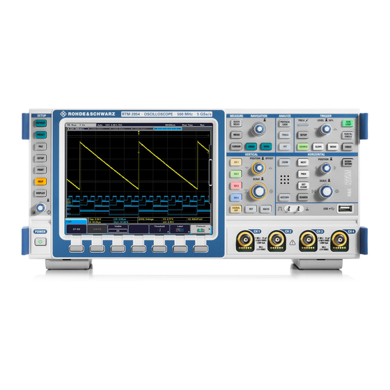
® Instrument Tour R&S RTM2000 Front Panel 3 Instrument Tour This chapter provides an overview of the front and rear panels of the instrument. 3.1 Front Panel The front panel of the R&S RTM is shown in figure 3-1. The function keys are grouped in functional blocks to the left and the right of the display. -
Page 46: Setup Controls
® Instrument Tour R&S RTM2000 Front Panel 3.1.1 SETUP Controls The SETUP keys and knob on the left of the display set the instrument to a defined state, change basic settings, and provide print and help functions. AUTOSET Resets the instrument to the default state, analyzes the active channel signals, and obtains appropriate horizontal, vertical, and trigger settings to display stable wave- forms. -
Page 47: Measure Keys
® Instrument Tour R&S RTM2000 Front Panel The virtual screen enlarges the screen to 20 vertical divisions in order to keep high ver- tical resolution and good overview when many waveforms are active. 8 of the 20 divi- sions are visible. Turn the knob to scroll the virtual screen. You can disable the virtual screen in the "Display"... -
Page 48: Analyze Keys
® Instrument Tour R&S RTM2000 Front Panel NAVIGATION The function of this universal rotary knob depends on the usage context: ● If a softkey with numerical entry or selection menu is selected, turn the knob to set a value. ● Pressing the knob closes the selection menu. -
Page 49: Trigger Controls
® Instrument Tour R&S RTM2000 Front Panel ● If option R&S RTM-K18 is installed, the FFT key enables the spectrum analysis mode. ● Without the option, the FFT key enables the basic Fast Fourier Transformation (FFT) calculation for the most recently selected channel. If activated, the FFT key lights up. -
Page 50: Vertical Controls
® Instrument Tour R&S RTM2000 Front Panel If the trigger type has one trigger leven, pressing the knob sets the level to 50% of the signal amplitude. If the trigger type requires two trigger levels, for example, the rise time/fall time trigger, pressing the knob toggles between upper and lower level. -
Page 51: Horizontal Controls
® Instrument Tour R&S RTM2000 Front Panel CH N Each channel key turns on an analog channel, selects it, and opens the "Channel" menu with the vertical settings of the selected channel. The key is illuminated in the channel color, if the channel is active. The effect of the keypress depends on state of the channel: ●... - Page 52 ® Instrument Tour R&S RTM2000 Front Panel POSITION In a normal waveform window, the rotary knob changes the trigger offset. The trigger offset is the horizontal position of the trigger point in relation to the reference point - the zero point of the grid. Thus, you can set the trigger point even outside the diagram and analyze the signal some time before or after the trigger.
-
Page 53: Input Channels
® Instrument Tour R&S RTM2000 Front Panel Note: If another marker is available at the right, but currently not visible on the screen, a small red arrow is displayed at the right edge of the display. PREV Moves the previous (left) marker to the reference point of the display or zoom area. If a search is enabled, the key navigates the search result markers. -
Page 54: Front Connectors
® Instrument Tour R&S RTM2000 Rear Panel Risk of injury and instrument damage The instrument is not rated for any measurement category; make sure that the input voltage does not exceed 200 V peak, 150 V RMS at 1 MΩ input impedance and 5 V RMS at 50 Ω... - Page 55 ® Instrument Tour R&S RTM2000 Rear Panel Fig. 3-2: Rear panel view of R&S RTM 1 = AC power supply connector and main power switch 2 = LAN connector 3 = USB connector, type B 4 = USB connector, type A 5 = Trigger output 6 = DVI-D connector for external monitor 7 = External trigger input...
-
Page 56: Right Panel
® Instrument Tour R&S RTM2000 Right Panel EXT TRIGGER INPUT The female connector for external trigger input is used to control the measurement with an external signal. The input impedance is 1 MΩ for instrument with < 1 GHz band- width. - Page 57 ® Instrument Tour R&S RTM2000 Right Panel Fig. 3-3: Right panel view of R&S RTM Getting Started 1317.4710.02 ─ 05...
-
Page 58: Trying Out The Instrument
® Trying Out the Instrument R&S RTM2000 Displaying a Basic Signal 4 Trying Out the Instrument This chapter introduces the most important functions and settings of the R&S RTM step by step. The complete description of the functionality and its usage is given in the "User Manual". -
Page 59: Zooming Into The Waveform
® Trying Out the Instrument R&S RTM2000 Zooming into the Waveform 4.2 Zooming into the Waveform Using the SCALE rotary knobs you can change the scaling of the time base and signal amplitudes in order to enlarge the waveform. If you want to see more details, use the zoom function. - Page 60 ® Trying Out the Instrument R&S RTM2000 Zooming into the Waveform 2. Turn the horizontal SCALE knob clockwise to see more details. Note the zoom area that is marked in the upper window. Getting Started 1317.4710.02 ─ 05...
- Page 61 ® Trying Out the Instrument R&S RTM2000 Zooming into the Waveform 3. Press the horizontal SCALE knob until "Time Control" mode is displayed. 4. Turn the horizontal SCALE and POSITION knobs. The time base of the channel 1 waveform changes, and the position of the zomm area, too.
-
Page 62: Using The Virtual Screen
® Trying Out the Instrument R&S RTM2000 Using the Virtual Screen 5. Press the ZOOM key again. The zoom window closes. 4.3 Using the Virtual Screen The virtual screen allows you to distribute the waveforms over 20 divisions. 8 of these divisions are visible. -
Page 63: Showing Basic Measurement Results
® Trying Out the Instrument R&S RTM2000 Showing Basic Measurement Results 4.4 Showing Basic Measurement Results All available basic measurement results for the selected channel can be displayed by pressing a single key - QUICK MEAS. The results are displayed either directly next to the waveform or in the result table beneath the diagram. - Page 64 ® Trying Out the Instrument R&S RTM2000 Showing Basic Measurement Results Automatic measurements To obtain more complex measurement results, or results from several channels simul- taneously, you can configure up to four amplitude and time measurements or pulse counts, based on the active signal or math waveforms. For example, you can compare the amplitudes of an active signal waveform with those of a reference waveform.
-
Page 65: Performing Cursor Measurements
® Trying Out the Instrument R&S RTM2000 Performing Cursor Measurements 7. Press "Measure 2" until "On" is highlighted. 8. Press "Meas. Type" until "Base Level" is highlighted. 9. Press "Source" until "CH1" is highlighted. The top and base level values of the active signal are displayed in the result table. 10. - Page 66 ® Trying Out the Instrument R&S RTM2000 Performing Cursor Measurements 1. Press the CURSOR key. The cursor lines are switched on. 2. Press "Meas. Type" until "Voltage & Time" is highlighted. 3. Press "Source" until "CH1" is highlighted. 4. Press the NAVIGATION rotary knob to select the first cursor. Turn the rotary knob to move the cursor line to the beginning of a pulse.
-
Page 67: Using Mathematical Functions
® Trying Out the Instrument R&S RTM2000 Using Mathematical Functions 7. Press "Cursor" to turn off the cursor lines. 4.6 Using Mathematical Functions In addition to the measured waveforms, you can display calculated data to compare the current measurement result with. Five mathematical waveforms are available that can be configured to perform various calculations on the available source signals. - Page 68 ® Trying Out the Instrument R&S RTM2000 Using Mathematical Functions 8. Press "Back" to exit the editor and return to the main "Mathematics" menu. The integral values of the signal channel are displayed as an additional waveform. If necessary, change the vertical scaling of the math waveform to improve the dis- play using the vertical SCALE rotary knob.
- Page 69 ® Trying Out the Instrument R&S RTM2000 Using Mathematical Functions 10. To display the integral of a single pulse, configure a V-marker cursor whose source is the first math waveform ("MA1" or "Integral") and position the cursors at the beginning and at the end of the pulse. The procedure is described in the previous example, chapter 4.5, "Performing Cur- Measurements",...
-
Page 70: Printing Results
® Trying Out the Instrument R&S RTM2000 Printing Results 4.7 Printing Results You can print screenshots of the current display to document your results. For improved readability, you can invert the colors displayed on the screen for printing, i.e. a dark waveform is printed on a white background. 1. -
Page 71: Storing Data
® Trying Out the Instrument R&S RTM2000 Storing Data For your convenience, you can configure print settings initially and then print screen- shots simply by pressing the PRINT key at any time during your measurement. This procedure is described in "Quick Access with PRINT Key" in the "User Manual". 4.8 Storing Data After a measurement with the R&S RTM, you can save the results for further evalua- tion or comparison. -
Page 72: Operating The Instrument
® Operating the Instrument R&S RTM2000 Understanding Display Information 5 Operating the Instrument There are two ways to operate the R&S RTM: ● Manual operation: Use the function keys, rotary knobs and softkeys on the front panel to control the instrument. The principles of manual operation are explained in this section. - Page 73 ® Operating the Instrument R&S RTM2000 Understanding Display Information 1 = Information bar 2 = Waveform labels 3 = Waveform window 4 = Information bar of the Zoom window 5 = Zoom window 6 = Results table 7 = Menu 8 = Trigger position Virtual screen The virtual screen expands the screen from 8 to 20 divisions and supports simultane-...
-
Page 74: Working With Waveforms
® Operating the Instrument R&S RTM2000 Working with Waveforms 1 = Time base (horizontal scale) 2 = Trigger offset (horizontal position) 3 = Trigger mode 4 = Trigger settings: Trigger source, trigger type settings (for Edge trigger: level, slope, coupling, filter) 5 = Sample rate 6 = Acquisition mode. -
Page 75: Accessing The Functionality
® Operating the Instrument R&S RTM2000 Accessing the Functionality ● Math waveforms: Five mathematic waveforms can be created with mathematic operations performed on channel, reference and other math waveforms. Four math waveforms can be displayed on the screen. ● Zoom waveforms show the details of the active waveforms ●... - Page 76 ® Operating the Instrument R&S RTM2000 Accessing the Functionality ● Another group of function keys directly start an action or change a parameter - for example, AUTOSET, PRINT, RUN CONT, MODE. ● The FFT and ZOOM keys start the corresponding display mode and open the associated menu.
-
Page 77: Entering Data
® Operating the Instrument R&S RTM2000 Entering Data ● Press the key until the required value is highlighted. ● Turn the NAVIGATION knob until the required value is highlighted. 3. To close a selection menu immediately, press the NAVIGATION knob. Otherwise, the selection menu closes automatically when the "Menu Off"... -
Page 78: Getting Help
® Operating the Instrument R&S RTM2000 Getting Help To enter data with the on-screen keypad or keyboard On-screen keypad and keyboard are used in the same way. When text input is required, the on-screen keyboard is displayed automatically. 1. For each character to be entered, turn the NAVIGATE knob until the required char- acter is highlighted, then press the knob. -
Page 79: Instrument Setup
® Instrument Setup R&S RTM2000 Defining General Instrument Settings 6 Instrument Setup 6.1 Defining General Instrument Settings This chapter describes how to define general instrument settings. 6.1.1 Setting Data and Time Year, month, day, hour and minute can be set individually. 1. -
Page 80: Performing A Self-Alignment
® Instrument Setup R&S RTM2000 Performing a Self-Alignment To set a language 1. Press SETUP > "Language". 2. Press the key for the required language. If the online help is not available for the selected language, the English help is dis- played. - Page 81 ® Instrument Setup R&S RTM2000 Adjusting Passive Probes Two connector pins are located on the front panel. The right pin is on ground level. The left pin supplies a square wave signal for the adjustment. You can choose between two frequencies for usual low frequency compensation and additional high frequency com- pensation.
-
Page 82: Maintenance
® Maintenance R&S RTM2000 Cleaning 7 Maintenance The instrument does not need a periodic maintenance. Only the cleaning of the instru- ment is essential. To protect the front panel and to transport the instrument to another workplace safely and easily, two accessories are provided: ●... -
Page 83: Storing And Packing
® Maintenance R&S RTM2000 Storing and Packing Risk of instrument damage due to obstructed fans If the instrument is operated in dusty areas, the fans may become obstructed by dust or other particles in the process of time. Make sure to check and, if necessary, clean the fans regularly to ensure they operate properly at all times. -
Page 84: Data Security
® Maintenance R&S RTM2000 Data Security 7.4 Data Security If you have to send the instrument to the service, or if the instrument is used in a secured environment, consider the document "Instrument Security Procedures" that is delivered on the documentation CD-ROM and on the R&S RTM internet web page. You can delete all current instrument configuration data and user data with SETUP >... -
Page 85: Index
® Index R&S RTM2000 Index Acquisition Kensington lock ..............23 Limited number ............18 Keys Start and stop ............. 18 ACQUISITION ............22 ACQUISITION ..............22 AUTOSET ..............15 Active waveform ..............44 CH N ................20 AUTOSET ................. 15 CURSOR .............. - Page 86 ® Index R&S RTM2000 Printer ................13 Probes Compensation connectors .......... 23 Virtual screen .............. 15, 42 passive, compensation ..........49 PROTOCOL LOGIC ............17 Waveforms Channel ..............43 QUICK MEAS ..............16 Display intensity ............15 Math ................43 Overview and usage ........... 43 Reference ..............
Need help?
Do you have a question about the RTM2000 Series and is the answer not in the manual?
Questions and answers