
Related Manuals for Dell EMC PowerEdge T340


Summary of Contents for Dell EMC PowerEdge T340
- Page 1 Dell EMC PowerEdge T340 Installation and Service Manual Regulatory Model: E60S Regulatory Type: E60S001 June 2020 Rev. A06...
- Page 2 A WARNING indicates a potential for property damage, personal injury, or death. © 2018 - 2019 Dell Inc. or its subsidiaries. All rights reserved. Dell, EMC, and other trademarks are trademarks of Dell Inc. or its subsidiaries. Other trademarks may be trademarks of their respective owners.
-
Page 3: Table Of Contents
Contents 1 About this document........................7 2 Dell EMC PowerEdge T340 system overview.................. 8 Front view of the system..............................9 Rear view of the system..............................11 Inside the system..................................12 Locating the information tag of your system........................14 System information label..............................14 3 PowerEdge T340 initial system setup and configuration.............. - Page 4 Removing the system feet............................42 Installing the system feet..............................43 Caster wheels – optional..............................44 Removing caster wheels...............................44 Installing caster wheels..............................45 System cover..................................46 Removing the system cover............................46 Installing the system cover............................47 Air shroud..................................... 48 Removing the air shroud...............................48 Installing the air shroud..............................
- Page 5 Expansion cards .................................. 78 Expansion card guidelines............................. 78 Removing an expansion card............................78 Installing an expansion card............................80 M.2 SSD module...................................81 Removing the M.2 SSD module........................... 81 Installing the M.2 SSD module............................. 82 Optional IDSDM or vFlash module............................ 83 Removing the optional IDSDM or vFlash card......................83 Installing optional IDSDM or vFlash card........................
- Page 6 9 Getting help..........................123 Recycling or End-of-Life service information.........................123 Contacting Dell................................... 123 Accessing system information by using QRL......................... 123 Quick Resource Locator for Dell EMC PowerEdge T340 system................. 124 Receiving automated support with SupportAssist ....................... 124 10 Documentation resources......................125 Contents...
-
Page 7: About This Document
About this document This document provides an overview about the system, information about installing and replacing components, technical specifications, diagnostic tools, and guidelines to be followed while installing certain components. About this document... -
Page 8: Dell Emc Poweredge T340 System Overview
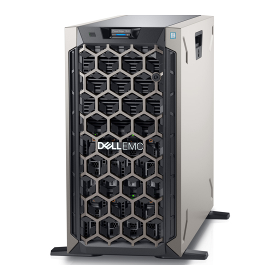
Dell EMC PowerEdge T340 system overview The Dell EMC PowerEdge T340 system is a tower server that supports: • One Intel Xeon, Core i3, Pentium, or Celeron processor • Four DIMM slots • Redundant and cabled AC power supply units •... -
Page 9: Front View Of The System
Figure 1. Front view of 8 x 3.5-inch drive system 1. Power button 2. Information tag 3. System health and system ID indicator 4. USB 3.0 port 5. iDRAC direct micro USB port 6. Optical drive (optional) 7. Drive (8) Dell EMC PowerEdge T340 system overview... - Page 10 4. USB 3.0 port 5. iDRAC direct micro USB port 6. Optical drive (optional) 7. Drive (4) 8. Four-slot drive blank For more information about the ports, see the Ports and connectors specifications section. Dell EMC PowerEdge T340 system overview...
-
Page 11: Rear View Of The System
4. System Identification button 5. USB 3.0 port (2) 6. iDRAC dedicated NIC port 7. VGA port 8. Serial port 9. NIC port (Gb1) 10. NIC port (Gb2) 11. PCIe expansion card slots (4) Dell EMC PowerEdge T340 system overview... -
Page 12: Inside The System
For more information about the ports and connectors, see the Ports and connectors specifications section. Inside the system NOTE: Components that are hot swappable are marked orange and touch points on the components are marked blue. Dell EMC PowerEdge T340 system overview... - Page 13 2. Power interposer board 3. PCIe Expansion card latch (4) 4. PCIe Expansion card slots (4) 5. Intrusion switch 6. Fan 7. Memory module socket (4) 8. Processor and heat sink 9. System board 10. Drive backplane Dell EMC PowerEdge T340 system overview...
-
Page 14: Locating The Information Tag Of Your System
Tag by pulling out the information tag located on the front of the system. Alternatively, the information may be on the Mini Enterprise Service Tag (MEST) label on the chassis, on the rear of the system. This information is used by Dell to route support calls to the appropriate personnel. - Page 15 Figure 9. Electrical overview Figure 10. Icon legend Figure 11. DVD and BOSS installation Figure 12. CPU installation Dell EMC PowerEdge T340 system overview...
- Page 16 Figure 13. Heat sink installation Figure 14. Internal cooling fan installation Figure 15. Memory population Figure 16. Quick resource locator Dell EMC PowerEdge T340 system overview...
-
Page 17: Poweredge T340 Initial System Setup And Configuration
For more information about setting up your system, see the Getting Started Guide that shipped with your system. iDRAC configuration The Integrated Dell Remote Access Controller (iDRAC) is designed to make system administrators more productive and improve the overall availability of Dell systems. iDRAC alerts administrators about system issues and enables them to perform remote system management. -
Page 18: Options To Install The Operating System
Ensure that you change the default user name and password after setting up the iDRAC IP address. For more information about logging in to the iDRAC and iDRAC licenses, see the latest Integrated Dell Remote Access Controller User's Guide at www.dell.com/poweredgemanuals. -
Page 19: Downloading Drivers And Firmware
Downloading drivers and firmware Dell EMC recommends that you download and install the latest BIOS, drivers, and systems management firmware on your system. Prerequisites Ensure that you clear the web browser cache before downloading the drivers and firmware. Steps 1. Go to www.dell.com/support/home. -
Page 20: Poweredge T340 Pre-Operating System Management Applications
You can manage basic settings and features of a system without booting to the operating system by using the system firmware. Topics: • Options to manage the pre-operating system applications • System Setup • Dell Lifecycle Controller • Boot Manager • PXE boot Options to manage the pre-operating system applications Your system has the following options to manage the pre-operating system applications: •... -
Page 21: System Setup Details
The iDRAC settings utility is an interface to set up and configure the iDRAC parameters by using UEFI (Unified Extensible Firmware Interface). You can enable or disable various iDRAC parameters by using the iDRAC settings utility. For more information about this utility, see Integrated Dell Remote Access Controller User’s Guide at www.dell.com/poweredgemanuals. - Page 22 Option Description System Profile Specifies options to change the processor power management settings, memory frequency. Settings System Security Specifies options to configure the system security settings, such as system password, setup password, Trusted Platform Module (TPM) security, and UEFI secure boot. It also manages the power button on the system. Redundant OS Sets the redundant OS info for redundant OS control.
- Page 23 Option Description UEFI Compliance Specifies the UEFI compliance level of the system firmware. Version Memory Settings You can use the Memory Settings screen to view all the memory settings and enable or disable specific memory functions, such as system memory testing and node interleaving. Viewing Memory Settings To view the Memory Settings screen, perform the following steps: Steps...
- Page 24 Processor Settings You can use the Processor Settings screen to view the processor settings, and perform specific functions such as enabling virtualization technology, hardware prefetcher, and logical processor idling. Viewing Processor Settings To view the Processor Settings screen, perform the following steps: Steps 1.
- Page 25 Option Description Option Description Level 3 Cache Specifies the total L3 cache. Number of Cores Specifies the number of cores per processor. Microcode Specifies the microcode. SATA Settings You can use the SATA Settings screen to view the SATA settings of SATA devices and enable SATA on your system. Viewing SATA Settings To view the SATA Settings screen, perform the following steps: Steps...
- Page 26 Boot Settings You can use the Boot Settings screen to set the boot mode to either BIOS or UEFI. It also enables you to specify the boot order. • UEFI: The Unified Extensible Firmware Interface (UEFI) is a new interface between operating systems and platform firmware. The interface consists of data tables with platform related information, boot and runtime service calls that are available to the operating system and its loader.
- Page 27 Option Description UEFI Boot Enables you to change the boot device order. Sequence Boot Options Enables you to select the enabled or disabled boot devices. Enable/Disable Network Settings You can use the Network Settings screen to modify UEFI PXE, iSCSI, and HTTP boot settings. The network settings option is available only in the UEFI mode.
- Page 28 Option Description Table 3. UEFI iSCSI Settings screen details(continued) Option Description iSCSI Device1 Settings Enables you to control the configuration of the iSCSI device. Integrated Devices You can use the Integrated Devices screen to view and configure the settings of all integrated devices including the video controller, integrated RAID controller, and the USB ports.
- Page 29 Option Description I/OAT DMA Enables or disables the I/O Acceleration Technology (I/OAT) option. I/OAT is a set of DMA features designed to Engine accelerate network traffic and lower CPU utilization. Enable only if the hardware and software support the feature. Embedded Video Enables or disables the use of Embedded Video Controller as the primary display.
- Page 30 2. Press F2 immediately after you see the following message: F2 = System Setup NOTE: If your operating system begins to load before you press F2, wait for the system to finish booting, and then restart your system and try again. 3.
- Page 31 2. Press F2 immediately after you see the following message: F2 = System Setup NOTE: If your operating system begins to load before you press F2, wait for the system to finish booting, and then restart your system and try again. 3.
- Page 32 System Security You can use the System Security screen to perform specific functions such as setting the system password, setup password and disabling the power button. Viewing System Security To view the System Security screen, perform the following steps: Steps 1.
- Page 33 Option Description NOTE: The SGX menu is available, only when the SGX supported processor is installed. SGX Launch Allows controlling the Launch Control Policy (LCP) of Software Guard Extensions (SGX) technology. This option Control Policy is set to Unlocked by default. Power Button Enables or disables the power button on the front of the system.
- Page 34 Option Description Secure Boot Configures the Secure Boot Custom Policy. To enable this option, set the Secure Boot Policy to Custom option. Custom Policy Settings Creating a system and setup password Prerequisites Ensure that the password jumper is enabled. The password jumper enables or disables the system password and setup password features. For more information, see the System board jumper settings section.
- Page 35 Deleting or changing system and setup password Prerequisites NOTE: You cannot delete or change an existing system or setup password if the Password Status is set to Locked. Steps 1. To enter System Setup, press F2 immediately after turning on or restarting your system. 2.
- Page 36 NOTE: If your operating system begins to load before you press F2, wait for the system to finish booting, and then restart your system and try again. 3. On the System Setup Main Menu screen, click System BIOS. 4. On the System BIOS screen, click Redundant OS Control. Redundant OS Control screen details The Redundant OS Control screen details are explained as follows: About this task...
-
Page 37: Idrac Settings Utility
Dell Lifecycle Controller Dell Lifecycle Controller (LC) provides advanced embedded systems management capabilities including system deployment, configuration, update, maintenance, and diagnosis. LC is delivered as part of the iDRAC out-of-band solution and Dell system embedded Unified Extensible Firmware Interface (UEFI) applications. -
Page 38: Boot Manager
Certain platform configurations may not support the full set of features provided by the Dell Lifecycle Controller. For more information about setting up the Dell Lifecycle Controller, configuring hardware and firmware, and deploying the operating system, see the Dell Lifecycle Controller documentation at www.dell.com/poweredgemanuals. - Page 39 To access the PXE boot option, boot the system and then press F12 during POST instead of using standard Boot Sequence from BIOS Setup. It does not pull any menu or allows managing of network devices. PowerEdge T340 Pre-operating system management applications...
-
Page 40: Installing And Removing System Components
Damage due to servicing that is not authorized by Dell is not covered by your warranty. Read and follow the safety instructions that are shipped with your product. -
Page 41: Front Bezel
• Key to the bezel lock The key is required only if your system includes a bezel. • Phillips #1 screwdriver • Phillips #2 screwdriver • 5mm hex nut screwdriver • Plastic scribe • Wrist grounding strap connected to the ground •... -
Page 42: System Feet
2. Locate and remove the bezel key. NOTE: The bezel key is part of the bezel package. Steps 1. Align and insert the bezel tabs into the slots in the system. 2. Press the release latch, and push the bezel toward the system until the bezel locks into place. 3. -
Page 43: Installing The System Feet
Figure 19. Removing the system feet Next steps Replace the system feet install the caster wheels. Installing the system feet Prerequisites CAUTION: Install the feet on a stand-alone tower system to provide stability to the system. An unstable system might tip over and cause injury to the user or damage to the system. -
Page 44: Caster Wheels - Optional
Figure 20. Installing the system feet Next steps 1. Place the system upright on a flat, stable surface, and rotate the system feet outward. 2. Follow the procedure listed in After working inside your system. Caster wheels – optional Removing caster wheels Prerequisites 1. -
Page 45: Installing Caster Wheels
Next steps Replace the caster wheels replace the system feet, as applicable. Installing caster wheels Prerequisites 1. Follow the safety guidelines listed in Safety instructions. 2. Place the system on its side on a flat, stable surface. 3. If installed, remove the system feet. -
Page 46: System Cover
Figure 21. Installing caster wheels Next steps 1. Follow the procedure listed in After working inside your system. System cover Removing the system cover Prerequisites 1. Follow the safety guidelines listed in Safety instructions. 2. Power off the system and all attached peripherals. 3. -
Page 47: Installing The System Cover
Figure 22. Removing the system cover Installing the system cover Prerequisites 1. Follow the safety guidelines listed in Safety instructions. Remove the front bezel. 3. Power off the system and all attached peripherals. 4. Disconnect the system from the electrical outlet and disconnect the peripherals. 5. -
Page 48: Air Shroud
Figure 23. Installing the system cover Next steps 1. Place the system upright on its feet on a flat, stable surface. Install the front bezel. 3. Reconnect the peripherals, and connect the system to the electrical outlet. 4. Power on the system and all attached peripherals. Air shroud Removing the air shroud Prerequisites... -
Page 49: Installing The Air Shroud
Figure 24. Removing the air shroud Next steps Replace the air shroud. Installing the air shroud Prerequisites 1. Follow the safety guidelines listed in Safety instructions. 2. Follow the procedure listed in Before working inside your system. 3. If applicable, route the cables inside the system along the system wall and secure the cables by using the cable-securing bracket. Steps 1. -
Page 50: Intrusion Switch
Figure 25. Installing the air shroud Next steps Install the system cover. 2. Follow the procedure listed in Before working inside your system. Intrusion switch Removing the intrusion switch Prerequisites 1. Follow the safety guidelines listed in Safety instructions. 2. Follow the procedure listed in Before working inside your system. -
Page 51: Installing The Intrusion Switch
Figure 26. Removing the intrusion switch Next steps Replace the intrusion switch. Installing the intrusion switch Prerequisites 1. Follow the safety guidelines listed in Safety instructions. 2. Follow the procedure listed in Before working inside your system. Steps 1. Align and slide the intrusion switch into the slot in the system. 2. -
Page 52: Drives
Next steps Install the air shroud. 2. Follow the procedure that is listed in After working inside your system. Drives Removing a drive blank Prerequisites 1. Follow the safety guidelines listed in Safety instructions. 2. Follow the procedure listed in Before working inside your system. -
Page 53: Removing A Drive Carrier
Steps Slide the drive blank into the drive slot until the release tab clicks into place. Figure 29. Installing a drive blank Next steps Replace the front bezel. 2. Follow the procedure listed in After working inside your system. Removing a drive carrier Prerequisites 1. -
Page 54: Installing The Drive Carrier
Figure 30. Removing a drive carrier Next steps Replace the drive or a drive blank. Installing the drive carrier Prerequisites CAUTION: Before removing or installing a drive while the system is running, see the documentation for the storage controller card to ensure that the host adapter is configured correctly to support drive removal and insertion. CAUTION: Combining SAS and SATA drives in the same RAID volume is not supported. -
Page 55: Removing The Drive From The Drive Carrier
NOTE: The procedure to install a 2.5-inch or a 3.5-inch drive are the same. Figure 31. Installing a drive carrier Next steps Install the front bezel. 2. Follow the procedure listed in After working inside your system. Removing the drive from the drive carrier Prerequisites 1. -
Page 56: Installing The Drive Into The Drive Carrier
Figure 32. Removing the drive from the drive carrier Next steps Replace the drive into the drive carrier. Installing the drive into the drive carrier Prerequisites 1. Follow the safety guidelines listed in Safety instructions. 2. Follow the procedure listed in Before working inside your system. -
Page 57: Removing A 2.5-Inch Drive From The 3.5-Inch Drive Adapter
Figure 33. Installing a drive into the drive carrier Next steps Replace the drive carrier. Install the front bezel. 3. Follow the procedure listed in After working inside your system. Removing a 2.5-inch drive from the 3.5-inch drive adapter Prerequisites 1. -
Page 58: Installing A 2.5-Inch Drive Into The 3.5-Inch Drive Adapter
Figure 34. Removing a 2.5-inch drive from the 3.5-inch drive adapter Next steps Replace a 2.5-inch drive into the 3.5-inch drive adapter. Installing a 2.5-inch drive into the 3.5-inch drive adapter Prerequisites Follow the safety guidelines listed in Safety instructions. Steps 1. -
Page 59: Removing A 3.5-Inch Drive Adapter From A 3.5-Inch Drive Carrier
Figure 35. Installing a 2.5-inch drive into the 3.5-inch drive adapter Next steps Replace a 3.5-inch adapter into the 3.5-inch drive carrier. 2. Follow the procedure listed in After working inside your system. Removing a 3.5-inch drive adapter from a 3.5-inch drive carrier Prerequisites 1. -
Page 60: Installing A 3.5-Inch Adapter Into A 3.5-Inch Drive Carrier
Figure 36. Removing a 3.5-inch drive adapter from a 3.5-inch drive carrier Next steps Replace a 3.5-inch adapter into a 3.5-inch drive carrier. Installing a 3.5-inch adapter into a 3.5-inch drive carrier Prerequisites Follow the safety guidelines listed in Safety instructions. -
Page 61: Optical Drive And Tape Drives
Next steps Replace a 3.5-inch drive carrier into the system. 2. Follow the procedure listed in After working inside your system. Optical drive and tape drives Removing the optical or tape drive blank Prerequisites NOTE: The procedure to remove the optical drive blank is identical to removing a tape drive blank. 1. -
Page 62: Installing The Optical Or Tape Drive Blank
Installing the optical or tape drive blank Prerequisites 1. Follow the safety guidelines listed in Safety instructions. Remove the front bezel. Steps 1. Align the guide on the drive blank with the slot on drive bay. 2. Slide the drive into the slot until the latch snaps into place. Figure 39. -
Page 63: Installing The Optical Drive
NOTE: Blanks must be installed on empty optical drive or tape drive slots to maintain FCC certification of the system. The brackets also keep dust and dirt out of the system and aid in proper cooling and airflow inside the system. -
Page 64: Removing The Tape Drive
Figure 41. Installing the optical drive Next steps Install the front bezel. 2. Follow the procedure listed in After working inside your system. Removing the tape drive Prerequisites 1. Follow the safety guidelines listed in Safety instructions. 2. Follow the procedure listed in Before working inside your system. -
Page 65: Installing The Tape Drive
Figure 42. Removing the tape drive Next steps Replace the tape drive. 2. Follow the procedure listed in After working inside your system. Installing the tape drive Prerequisites 1. Ensure that you follow the procedure listed in Safety instructions. 2. Follow the procedure listed in Before working inside your system. -
Page 66: Drive Backplane
Figure 43. Installing the tape drive Next steps Install the front bezel. 2. Follow the procedure listed in After working inside your system. Drive backplane Drive backplane details Your system supports the following backplane configuration: • x8 SAS/SATA backplane for 3.5-inch drives NOTE: The x8 backplane also supports up to eight 2.5-inch (SAS, SATA, or SSD) hot swappable drives that can be installed in 3.5-inch drive adapters, which can be installed in the 3.5-inch drive carriers. -
Page 67: Removing The Drive Backplane
Figure 44. x8 SAS/SATA backplane for 3.5-inch drives 1. ODD power connector (P1) 2. Backplane P4 power connector (BP_PWR) 3. Backplane sideband signal connector (BP_SIG) 4. Mini SAS SAS_A0 5. Mini SAS SAS_B0 Removing the drive backplane Prerequisites CAUTION: Note the number of each drive and temporarily label them before you remove the drive so that you can replace them in the same location. -
Page 68: Installing The Drive Backplane
Figure 45. Removing the drive backplane Next steps Replace a drive backplane. 2. Follow the procedure listed in After working inside your system. Installing the drive backplane Prerequisites 1. Follow the safety guidelines listed in Safety instructions. 2. Follow the procedure listed in Before working inside your system. -
Page 69: Backplane Cable Routing
Figure 46. Installing the drive backplane Next steps Install the air shroud. Install the drives. Install the front bezel. 4. Follow the procedure listed in After working inside your system. Backplane cable routing Figure 47. Cable routing - 8 x 3.5-inch, SATA drive backplane Installing and removing system components... -
Page 70: Four-Slot Drive Blank
Figure 48. Cable routing - 8 x 3.5-inch SAS/SATA drive backplane with PERC card Four-slot drive blank Systems with x8 drive backplanes configured for software RAID support only four drives. The remaining drive slots are pre-installed with the four-slot drive blank, and cannot be upgraded for additional storage. Removing a four-slot drive blank Prerequisites CAUTION:... -
Page 71: Installing A Four-Slot Drive Blank
Figure 49. Removing a four-slot drive blank Next steps Replace a four-slot drive blank. Installing a four-slot drive blank Prerequisites 1. Follow the safety guidelines listed in Safety instructions. 2. Follow the procedure listed in Before working inside your system. Steps 1. -
Page 72: System Memory
Next steps Install the drive backplane. Install the drives. Install the air shroud. 4. Follow the procedure listed in After working inside your system. System memory System memory guidelines The system supports DDR4 unbuffered DIMMs (UDIMMs). System memory holds the instructions that are executed by the processor. Your system contains 4 memory sockets. -
Page 73: General Memory Module Installation Guidelines
Table 6. Memory population DIMM Type DIMMs Populated/ Operating Frequency (in Maximum DIMM Rank/ Voltage Channel MT/s) Channel UDIMM 2133, 2400, 2666 Dual rank or single rank 1.2 V 2133, 2400, 2666 Dual rank or single rank General memory module installation guidelines To ensure optimal performance of your system, observe the following general guidelines when configuring your system memory. -
Page 74: Installing A Memory Module
2. Follow the procedure listed in Before working inside your system. Remove the air shroud. Steps 1. Locate the appropriate memory module socket. CAUTION: Handle each memory module only by the edges, ensuring not to touch the middle of the memory module or metallic contacts. -
Page 75: Cooling Fan
NOTE: The memory module socket has an alignment key that enables you to install the memory module in the socket in only one orientation. 4. Press the memory module with your thumbs until the ejectors firmly click into place. Figure 53. Installing a memory module Next steps Install the air shroud. -
Page 76: Installing The Internal Cooling Fan
Figure 54. Removing the internal cooling fan CAUTION: Do not remove or install the fan by holding the fan blades. Next steps Replace the internal fan. Installing the internal cooling fan Prerequisites 1. Follow the safety guidelines listed in Safety instructions. -
Page 77: Optional Internal Usb Memory Key
Figure 55. Installing the internal cooling fan Next steps Install the air shroud. 2. Follow the procedure listed in After working inside your system. Optional internal USB memory key NOTE: To locate the internal USB port on the system board, see the System board jumpers and connectors section. -
Page 78: Expansion Cards
A System Event Log (SEL) event is logged if an expansion card riser is not supported or missing. It does not Troubleshooting prevent your system from turning on. However, if a F1/F2 pause occurs with an error message, see expansion cards section in the Dell EMC PowerEdge Servers Troubleshooting Guide at www.dell.com/ poweredgemanuals. - Page 79 4. Disconnect any cables connected to the expansion card. Steps 1. If installed, disconnect the data cables from the PERC card. 2. Press the expansion card retention latch and push the latch downwards to open it. Figure 56. Removing an expansion card Figure 57.
-
Page 80: Installing An Expansion Card
Next steps Replace an expansion card. Install the air shroud. Installing an expansion card Prerequisites 1. Follow the safety guidelines listed in Safety instructions. 2. Follow the procedure listed in Before working inside your system. Steps 1. Open the expansion card retention latch. 2. -
Page 81: M.2 Ssd Module
Figure 59. Installing the filler bracket 6. Connect the data cables to the expansion card. Next steps Install the air shroud. 2. Connect the cables to the expansion card. 3. Follow the procedure listed in After working inside your system. M.2 SSD module Removing the M.2 SSD module Prerequisites... -
Page 82: Installing The M.2 Ssd Module
Figure 60. Removing the M.2 SSD module Next steps Replace the M.2 SSD module. Installing the M.2 SSD module Prerequisites 1. Follow the safety guidelines listed in Safety instructions. 2. Follow the procedure listed in Before working inside your system. Remove the air shroud. -
Page 83: Optional Idsdm Or Vflash Module
Figure 61. Installing the M.2 SSD module Next steps 1. Install the BOSS card. NOTE: The procedure to install the BOSS card is similar to removing an expansion card. Install the air shroud. 3. Follow the procedure listed in the After working inside your system. -
Page 84: Installing Optional Idsdm Or Vflash Card
Installing optional IDSDM or vFlash card Prerequisites 1. Follow the safety guidelines listed in the Safety instructions. 2. Follow the procedure listed in the Before working inside your system. Remove the air shroud. Steps 1. Locate the IDSDM/vFlash connector on the system board. To locate IDSDM/vFlash connector, see System board jumpers and connectors section. -
Page 85: Installing The Microsd Card
NOTE: Temporarily label each MicroSD card with its corresponding slot number after removal. Figure 63. Removing the MicroSD card Next steps Replace the MicroSD cards. Installing the MicroSD card Prerequisites 1. Follow the safety guidelines listed in the Safety instructions. 2. -
Page 86: Processor And Heat Sink
Figure 64. Installing the MicroSD card Next steps Install the IDSDM or vFlash module. 2. Follow the procedure listed in the After working inside your system. Processor and heat sink Removing the heat sink Prerequisites WARNING: The heat sink may be hot to touch for some time after the system is powered down. Allow the heat sink to cool before removing it. -
Page 87: Removing The Processor
Figure 65. Removing the heat sink Next steps 1. If you are removing a faulty heat sink, Replace the heat sink. Else, remove the processor. 2. Follow the procedure listed in After working inside your system. Removing the processor Prerequisites WARNING: The heat sink may be hot to touch for some time after the system has been powered down. -
Page 88: Installing The Processor
Figure 66. Removing the processer CAUTION: Do not touch the processor socket pins, they are fragile and can be permanently damaged. Be careful not to bend the pins in the processor socket when removing the processor out of the socket. Next steps Replace the processor into the processor and heat sink. -
Page 89: Installing The Heat Sink
Installing the heat sink Prerequisites 1. Follow the safety guidelines listed in Safety instructions. 2. Follow the procedure listed in Before working inside your system. Install the processor. Steps 1. If you are using an existing heat sink, remove the thermal grease from the heat sink by using a clean lint-free cloth. 2. -
Page 90: Power Supply Unit
Figure 69. Installing the heat sink Next steps Replace the air shroud. 2. Follow the procedure listed in After working inside your system. 3. While booting, press F2 to enter System Setup and verify that the processor information matches the new system configuration. 4. -
Page 91: Installing The Power Supply Unit Blank
Figure 70. Removing the power supply unit blank Next steps Install the PSU PSU blank. Installing the power supply unit blank Prerequisites 1. Follow the safety guidelines listed in Safety instructions. NOTE: Install the power supply unit (PSU) blank only in the second PSU bay. Remove the PSU. -
Page 92: Removing A Redundant Ac Power Supply Unit
Removing a redundant AC power supply unit Prerequisites 1. Follow the safety guidelines listed in Safety instructions. 2. Disconnect the power cable from the power outlet and from the PSU you want to remove, then remove the cable from the strap on the PSU handle. -
Page 93: Removing A Cabled Power Supply Unit
Figure 73. Installing a redundant power supply unit Next steps 1. Connect the power cable to the PSU, and plug the cable into a power outlet. CAUTION: When connecting the power cable to the PSU, secure the cable to the PSU with the strap. NOTE: When installing, hot swapping, or hot adding a new PSU, wait for 15 seconds for the system to recognize the PSU and determine its status. -
Page 94: Installing A Cabled Power Supply Unit
Figure 74. Removing a cabled power supply unit Next steps Replace a cabled PSU. Installing a cabled power supply unit Prerequisites 1. Follow the safety guidelines listed in Safety instructions. 2. Unpack the replacement power supply unit (PSU). Steps 1. Slide the PSU into the PSU bay in the chassis until the PSU is fully seated. 2. -
Page 95: Power Interposer Board
Figure 75. Installing a cabled power supply unit Next steps 1. Follow the procedure listed in After working inside your system. Power interposer board Removing the power interposer board Prerequisites 1. Follow the safety guidelines listed in Safety instructions. 2. Follow the procedure listed in Before working inside your system. -
Page 96: Installing The Power Interposer Board
Figure 76. Removing the power interposer board Next steps Replace the power interposer board (PIB). Installing the power interposer board Prerequisites 1. Follow the safety guidelines listed in Safety instructions. 2. Follow the procedure listed in Before working inside your system. -
Page 97: System Battery
System battery Replacing the system battery Prerequisites NOTE: There is a danger of a new battery exploding if it is incorrectly installed. Replace the battery only with the same or equivalent type that the manufacturer recommends. Discard used batteries according to the manufacturer's instructions. -
Page 98: System Board
Figure 79. Installing the system battery Next steps 1. Follow the procedure listed in After working inside your system. 2. Enter the System Setup to confirm that the battery is operating properly. 3. Enter the correct time and date in the System Setup's Time and Date fields. 4. - Page 99 CAUTION: To prevent damage to the processor pins when replacing a faulty system board, ensure that you cover the processor socket with the processor protective cap. Memory modules Steps 1. Disconnect all cables from the system board. CAUTION: Take care not to damage the system identification button while removing the system board from the system.
-
Page 100: Installing The System Board
Next steps Replace or install the system board. Installing the system board Prerequisites Follow the safety guidelines listed in Safety instructions. Steps 1. Unpack the new system board assembly. CAUTION: Do not lift the system board by holding a memory module, processor, or other components. CAUTION: Take care not to damage the system identification button while placing the system board into the system. - Page 101 5. Import your new or existing iDRAC Enterprise license. For more information, see iDRAC User's Guide, at www.dell.com/poweredgemanuals Restoring the system using Easy Restore The easy restore feature enables you to restore your service tag, license, UEFI configuration, and the system configuration data after replacing the system board.
-
Page 102: Trusted Platform Module
NOTE: You can enter the service tag only when the Service Tag field is empty. Ensure that you enter the correct service tag. Once the service tag is entered, it cannot be updated or changed. 5. Click OK. Trusted Platform Module Upgrading the Trusted Platform Module Prerequisites NOTE:... -
Page 103: Initializing Tpm For Bitlocker Users
Next steps Replace the system board. 2. Follow the procedure listed in After working inside your system. 3. To verify if the memory module has been installed properly, press F2 and navigate to System Setup Main Menu > System BIOS > Memory Settings. -
Page 104: Control Panel
Control panel Removing the control panel assembly Prerequisites 1. Follow the safety guidelines listed in Safety instructions. 2. Follow the procedure listed in Before working inside your system. Steps 1. Using the Phillips #2 screwdriver, remove the screw that secures control panel to the system. 2. - Page 105 2. To install the information tag, push the information tag into the control-panel slot. 3. Connect the control panel cable and the control panel USB cable to the control panel assembly. 4. Align and insert the control panel into the control panel slot in the system. 5.
-
Page 106: Poweredge T340 Jumpers And Connectors
PowerEdge T340 jumpers and connectors This topic provides specific information about the jumpers. It also provides some basic information about jumpers and switches and describes the connectors on the various boards in the system. Jumpers on the system board help to disable the system and setup passwords. -
Page 107: System Board Jumper Settings
Damage due to servicing that is not authorized by Dell is not covered by your warranty. Read and follow the safety instructions that are shipped with your product. - Page 108 Steps 1. Power off the system, including any attached peripherals, and disconnect the system from the electrical outlet. 2. Remove the system cover. 3. Move the jumper on the system board jumper from pins 2 and 4 to pins 4 and 6. 4.
-
Page 109: Technical Specifications
Technical specifications The technical and environmental specifications of your system are outlined in this section. Topics: • Chassis dimensions • System weight • Processor specifications • Supported operating systems • PSU specifications • Cooling fan specifications • System battery specifications •... -
Page 110: System Weight
Microsoft Windows Server • Red Hat Enterprise Linux • SUSE Linux Enterprise Server • VMware ESXi NOTE: For more information, go to www.dell.com/ossupport. PSU specifications The Dell EMC PowerEdge T340 system supports up to two AC power supply units (PSUs). Technical specifications... -
Page 111: Cooling Fan Specifications
Dell Energy Smart Solution Advisor available at Dell.com/ESSA. System battery specifications The Dell EMC PowerEdge T340 system supports CR 2032 3.0-V lithium coin cell system battery. Expansion card specifications The Dell EMC PowerEdge T340 system supports up to four PCI express (PCIe) Generation 3. -
Page 112: Storage Controller Specifications
Supported number of drives Dedicated SATA DVD-ROM drive or DVD +/-RW drive Tape drives The Dell EMC PowerEdge T340 system supports up to two dedicated 5.25-inch tape drives. Ports and connectors specifications USB ports specifications Table 19. Dell EMC PowerEdge T340 system USB port specifications... -
Page 113: Nic Ports Specifications
The Dell EMC PowerEdge T340 system supports up to two 10/100/1000 Mbps Network Interface Controller (NIC) ports that are located on the back panel. Serial connector specifications The Dell EMC PowerEdge T340 system supports one serial connector on the back panel, which is a 9-pin connector, Data Terminal Equipment (DTE), 16550-compliant. VGA ports specification The Dell EMC PowerEdge T340 system supports one 15-pin VGA port, on the back of the system. -
Page 114: Environmental Specifications
60, 75 8, 16, 24 Environmental specifications NOTE: For additional information about environmental certifications, refer to the Product Environmental Datasheet located with the Manuals & Documents on www.dell.com/support/home. Table 22. Temperature specifications Temperature Specifications Storage -40–65°C (-40–149°F) Continuous operation (for altitude less than 950 m 10–35°C (50–95°F) with no direct sunlight on the equipment... -
Page 115: Standard Operating Temperature
Cooling redundancy is not supported due to single fan only in system. • Support up to 80 W processor. • One system fan is required. • Non-Dell qualified peripheral cards and/or peripheral cards greater than 25 W are not supported. • GPU is not supported. Technical specifications... -
Page 116: Particulate And Gaseous Contamination Specifications
• Tape backup unit is supported. Particulate and gaseous contamination specifications The following table defines the limitations that help avoid any damages to the IT equipment and/or, or both failure from particulate and gaseous contamination. If the levels of particulate or gaseous pollution exceed the specified limitations and results in equipment damage or failure, you must rectify the environmental conditions. -
Page 117: System Diagnostics And Indicator Codes
Error Code Lookup page at qrl.dell.com iDRAC Direct LED indicator codes The iDRAC Direct LED indicator lights up to indicate that the port is connected and is being used as a part of the iDRAC subsystem. -
Page 118: Nic Indicator Codes
Table 33. iDRAC Direct LED indicator codes(continued) iDRAC Direct LED Condition indicator code Indicates that the laptop or tablet is unplugged. Powers off NIC indicator codes Each NIC on the back of the system has indicators that provide information about the activity and link status. The activity LED indicator indicates if data is flowing through the NIC, and the link LED indicator indicates the speed of the connected network. -
Page 119: Power Supply Unit Indicator Codes
Figure 90. Non-redundant cabled AC PSU status indicator and self-diagnostic button 1. Self-diagnostic button 2. AC PSU status indicator Table 35. Non-redundant AC PSU status indicator Power Indicator Pattern Condition Not lit Power is not connected or PSU is faulty. Green A valid power source is connected to the PSU and the PSU is operational. -
Page 120: Drive Indicator Codes
Table 36. AC PSU status indicator codes(continued) Power indicator codes Condition of PowerEdge servers is not supported, even if the PSUs have the same power rating. This results in a PSU mismatch condition or failure to power on the system. CAUTION: When correcting a PSU mismatch, replace only the PSU with the blinking indicator. -
Page 121: Poweredge T340 System Diagnostics
PowerEdge T340 system diagnostics If you experience a problem with your system, run the system diagnostics before contacting Dell for technical assistance. The purpose of running system diagnostics is to test your system hardware without using additional equipment or risking data loss. If you are unable to fix the problem yourself, service and support personnel can use the diagnostics results to help you solve the problem. - Page 122 System diagnostic controls Menu Description Configuration Displays the configuration and status information of all detected devices. Results Displays the results of all tests that are run. System health Provides the current overview of the system performance. Event log Displays a time-stamped log of the results of all tests run on the system. This is displayed if at least one event description is recorded.
-
Page 123: Getting Help
Contacting Dell Dell provides several online and telephone based support and service options. If you do not have an active internet connection, you can find contact information about your purchase invoice, packing slip, bill, or Dell product catalog. Availability varies by country and product, and some services may not be available in your area. -
Page 124: Quick Resource Locator For Dell Emc Poweredge T340 System
Receiving automated support with SupportAssist Dell EMC SupportAssist is an optional Dell EMC Services offering that automates technical support for your Dell EMC server, storage, and networking devices. By installing and setting up a SupportAssist application in your IT environment, you can receive the following benefits: •... -
Page 125: Documentation Resources
Configuring your system For information about the iDRAC features, www.dell.com/poweredgemanuals configuring and logging in to iDRAC, and managing your system remotely, see the Integrated Dell Remote Access Controller User's Guide. For information about understanding Remote Access Controller Admin (RACADM) subcommands and supported RACADM interfaces, see the RACADM CLI Guide for iDRAC. - Page 126 For information about installing, using, and www.dell.com/openmanagemanuals > troubleshooting Dell OpenManage Enterprise, see OpenManage Enterprise the Dell OpenManage Enterprise User’s Guide. For information about installing and using Dell www.dell.com/serviceabilitytools SupportAssist, see the Dell EMC SupportAssist Enterprise User’s Guide. For information about partner programs enterprise www.dell.com/openmanagemanuals...
Need help?
Do you have a question about the EMC PowerEdge T340 and is the answer not in the manual?
Questions and answers