Table of Contents
Advertisement
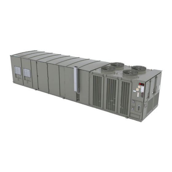
Installation, Operation, and Maintenance
IntelliPak™ ™ 1 with Symbio
Commercial Packaged Rooftop Air Conditioners
with VAV or SZVAV Controls and eFlex™/
eDrive™
Only qualified personnel should install and service the equipment. The installation, starting up, and servicing of heating, ventilating, and air-conditioning
equipment can be hazardous and requires specific knowledge and training. Improperly installed, adjusted or altered equipment by an unqualified person
could result in death or serious injury. When working on the equipment, observe all precautions in the literature and on the tags, stickers, and labels that
are attached to the equipment.
April 2022
S S A A F F E E T T Y Y W W A A R R N N I I N N G G
R R T T - - S S V V X X 0 0 7 7 2 2 A A - - E E N N
® ®
800
Advertisement
Table of Contents

Related Manuals for Trane IntelliPak 1


Summary of Contents for Trane IntelliPak 1
- Page 1 Installation, Operation, and Maintenance IntelliPak™ ™ 1 with Symbio ® ® Commercial Packaged Rooftop Air Conditioners with VAV or SZVAV Controls and eFlex™/ eDrive™ S S A A F F E E T T Y Y W W A A R R N N I I N N G G Only qualified personnel should install and service the equipment.
- Page 2 A A L L W W A A Y Y S S r r e e f f e e r r t t o o a a p p p p r r o o p p r r i i a a t t e e S S a a f f e e t t y y D D a a t t a a impact to the environment. Trane advocates the...
- Page 3 Overview of Manual This document and the information in it are the property of Trane, and may not be used or reproduced N N o o t t e e : : This document is customer property and must be in whole or in part without written permission.
-
Page 4: Table Of Contents
Table of Contents Model Number Description ....7 Center of Gravity ......24 20 to 75 Tons, Air Cooled . - Page 5 T T a a b b l l e e o o f f C C o o n n t t e e n n t t s s Main Unit Power Wiring....51 Installation of New Units .
- Page 6 Heating Season ......153 Trane Startup Checklist ....130 Coil Cleaning .
-
Page 7: Model Number Description
Model Number Description 20 to 75 Tons, Air Cooled Digit 1 — Unit Type Digit 9 — Heating Capacity Digit 11— Relief/Return Option S = Self-Contained (Packaged Rooftop) Note: When the second digit is “F” (Gas 0 = None Heat), the following applies: (M and T 1 = Barometric are available ONLY on 50 ton and 3 = Relief 3 HP with Statitrac... - Page 8 M M o o d d e e l l N N u u m m b b e e r r D D e e s s c c r r i i p p t t i i o o n n Digit 13 —...
- Page 9 R = Rapid Restart Digit 35 — BAS/Communication Options Digit 29 — Miscellaneous Options 0 = None 7 = Trane LonTalk Communication Interface 0 = Motors without Internal Shaft Grounding Module A = Motors with Internal Shaft Grounding 8 = Modbus®...
-
Page 10: 90 To 130 Tons, Air Cooled
M M o o d d e e l l N N u u m m b b e e r r D D e e s s c c r r i i p p t t i i o o n n 90 to 130 Tons, Air Cooled Digit 1 —... - Page 11 Digit 35 — BAS/Communication 1 = Power Meter Options 0 = None Digit 26 — Efficiency Options 7 = Trane LonTalk Communication Interface Module 0 = Standard Efficiency Unit 8 = ModBus® H = High Efficiency Unit M = BACnet® Communication Interface (BCI) Module Digit 27 —...
-
Page 12: General Information
S_HL units is available One Mylar unit nameplate is located on the outside of from Trane. The roof curb kit must be field assembled enclosure. It includes the unit model number, serial and installed according to the latest edition of the roof number, electrical characteristics, weight, refrigerant curb installation manual. -
Page 13: Pre-Installation
Pre-Installation Unit Inspection • Do not remove damaged material from receiving location. To protect against loss due to damage incurred in • Take photos of the damage, if possible. transit, perform inspection immediately upon receipt of the unit. • The owner must provide reasonable evidence that the damage did not occur after delivery. -
Page 14: Information
Trane specifically authorized to perform startup). reassembly work. On all IntelliPak 1 units, a Trane factory startup is an • Start-up must be performed by Trane or an agent of option and provides maximized unit reliability and... -
Page 15: Installation Checklist
☐ Check the unit for shipping damage and material variable air volume controls as applicable. Refer to shortage; file a freight claim and notify Trane office. unit diagrams for guidelines. ☐ Verify that the installation location of the unit will... -
Page 16: Requirements For Steam Heat
P P r r e e - - I I n n s s t t a a l l l l a a t t i i o o n n ☐ Install the factory-supplied, 3-way modulating ☐ Use float and thermostatic traps in the system, as valve. -
Page 17: Dimensional Data
Dimensional Data Table 2. Heating/cooling unit dimensions (ft. in.) - air-cooled - SEH_, SFH_, SSH_, SLH_, SXH_ Nom. Tons 20, 25 24-1 3/8 7-6 1/2 0-9 1/2 1-3 5/8 1-7 9/16 1-3 1/2 2-2 1/2 24-1 3/8 7-6 1/2 0-9 1/2 1-3 5/8 1-7 9/16 1-3 1/2... - Page 18 D D i i m m e e n n s s i i o o n n a a l l D D a a t t a a Figure 1. Unit dimensions, SAH_ cooling only units (20 to 75 ton) N N o o t t e e : : Use the table that follows.
- Page 19 D D i i m m e e n n s s i i o o n n a a l l D D a a t t a a Figure 2. Unit base dimensions, SAH_ cooling only units (20 to 75 ton) N N o o t t e e : : Use table that follows.
- Page 20 D D i i m m e e n n s s i i o o n n a a l l D D a a t t a a Figure 3. Unit dimensions, SEH_, SFH_, SLH_, SSH_, SXH_ units (20 to 75 ton) N N o o t t e e : : Use the following two table for dimensions.
- Page 21 D D i i m m e e n n s s i i o o n n a a l l D D a a t t a a Table 6. CVPC furnace drain dimensions Dimensions (Note) Nom. Ton Furnace (AC/EC) Size/MBh...
- Page 22 D D i i m m e e n n s s i i o o n n a a l l D D a a t t a a Table 7. Unit base dimensions, SEH_, SFH_, SLH_, SSH_, SXH_ units (20 to 75ton)—air cooled Fan Type Nom.
- Page 23 D D i i m m e e n n s s i i o o n n a a l l D D a a t t a a Figure 5. S_H_ cooling and heating units (90-130 ton) Relief Air Outdoor Air 6' 9⅜"...
-
Page 24: Center Of Gravity
D D i i m m e e n n s s i i o o n n a a l l D D a a t t a a Center of Gravity Figure 6. Center of gravity dimensional data Condenser Section Top View... -
Page 25: Electrical Entry Details
D D i i m m e e n n s s i i o o n n a a l l D D a a t t a a Electrical Entry Details Figure 7. Electrical entrance dimensions, SAH_ cooling only units (20 to 75 ton) Unit Base Electrical Entrance Legend... - Page 26 D D i i m m e e n n s s i i o o n n a a l l D D a a t t a a Figure 8. Electrical entrance dimensions, SEH_, SFH_, SLH_, SXH_ units (20 to 75 tons) Unit Base Electrical Entrance Legend...
-
Page 27: Minimum Required Clearance
D D i i m m e e n n s s i i o o n n a a l l D D a a t t a a Minimum Required Clearance Figure 9. Minimum operation and service clearances for single and multiple unit installation Single Unit Installation NOT TO SCALE Legend... -
Page 28: Weights
100% economizer, throwaway filters, maximum motor sizes, 460V XL start, high capacity heat, and access doors. Weights shown represent approximate operating weights and have a ±10% accuracy. To calculate weight for a specific unit configuration, utilize TOPSS™ or contact the local Trane® sales representative. ACTUAL WEIGHTS ARE STAMPED ON THE UNIT NAMEPLATE. - Page 29 W W e e i i g g h h t t s s Table 12. Roof curb max weight (lbs./kg.) Roof Curb Max. Weight Unit SAH_ SEH_, SFH_, SLH_, SSH, SXH_ 20, 25, 30 40, 50, 55 60, 70, 75 90-130 Note: Roof curb weights include the curb and pedestal.
-
Page 30: Installation
Before installing any roof curb, verify the following: curb pedestal. • It is the correct curb for the unit. If a Trane Curb Accessory Kit is not used: • It includes the necessary gaskets and hardware. • The ductwork can be attached directly to the •... -
Page 31: Unit Rigging And Placement
1. To configure the unit Center-of-Gravity, utilize with the curb rail while lowering the unit onto the TOPSS or contact the local Trane sales office. curb. Make sure that the gasket on the curb is not damaged while positioning the unit. (The pedestal 2. -
Page 32: General Installation Requirements
I I n n s s t t a a l l l l a a t t i i o o n n Figure 11. Unit rigging Spreader Bar Lengths: – 8' for 20 to 59 ton unit Typical 40 to 130 Ton Unit Typical 20 to 36 Ton Unit –... -
Page 33: O/A Pressure Sensor And Tubing Installation
I I n n s s t t a a l l l l a a t t i i o o n n ☐ Remove the shipping hardware from each pressurize piping in excess of 0.50 psig or 14 inches compressor assembly. -
Page 34: Condensate Drain Connections
I I n n s s t t a a l l l l a a t t i i o o n n Condensate Drain Connections Units with Gas Furnace Units equipped with a gas furnace have a 3/4" CPVC Each unit is provided with 1"... -
Page 35: Optional Ddp Supply Fan Shipping Channel Removal And Isolator Spring
I I n n s s t t a a l l l l a a t t i i o o n n Optional DDP Supply Fan N N o o t t e e s s : : Shipping Channel Removal and •... - Page 36 I I n n s s t t a a l l l l a a t t i i o o n n Figure 15. DDP shipping channel removal, isolator spring adjustment SPRING ISOLATORS (2 EACH SIDE) SHIPPING TIE DOWN (2 - 4 EACH SIDE) ISOLATOR SPRING ADJUST BOLT ISOLATOR SPRING JAM NUT ISOLATION BASE...
- Page 37 I I n n s s t t a a l l l l a a t t i i o o n n Figure 16. Removing supply and relief fan assembly shipping hardware (20 to 75 ton) Rubber Isolator Locations DETAIL “A”...
- Page 38 I I n n s s t t a a l l l l a a t t i i o o n n Figure 17. Removing supply and relief fan assembly shipping hardware (90 to130 ton) Supply Fan Assembly TOP VIEW ISO-1 ISO-1...
-
Page 39: O/A Sensor And Tubing Installation
I I n n s s t t a a l l l l a a t t i i o o n n Figure 18. Removing return fan assembly shipping hardware (20 to 75 ton) RETURN FAN (20 to 75 Ton) TOP VIEW Shipping Tie Down (3) 25-30 Ton... -
Page 40: Gas Heat Units (Sfh_)
I I n n s s t t a a l l l l a a t t i i o o n n the largest open area that will not be affected by sudden static pressure changes. Figure 19. Pressure sensing Outside Air Sensing Kit Top Port Connection 2’... -
Page 41: Connecting The Gas Supply Line To The Furnace Gas Train
I I n n s s t t a a l l l l a a t t i i o o n n W W A A R R N N I I N N G G 6. Install a pressure regulator at the unit that is adequate to maintain 7"... - Page 42 I I n n s s t t a a l l l l a a t t i i o o n n configuration. recommended 7" to 14" w.c. parameter for natural gas. 1. Connect the supply gas piping using a “ground- joint”...
- Page 43 I I n n s s t t a a l l l l a a t t i i o o n n Table 16. Gas heating capacity altitude correction factors Altitude (Ft.) Sea Level To 2001 to 2501 to 3501 to 4501 to 5501 to...
- Page 44 I I n n s s t t a a l l l l a a t t i i o o n n Table 18. LP gas – 2-stage and modulating gas heat settings (continued) Propane 1150 1150 3920 0.516 850 MBH Mod 1000 MBH 2-stg...
-
Page 45: Flue Assembly Installation
I I n n s s t t a a l l l l a a t t i i o o n n Figure 23. Ultra modulating gas train for 500 to 850 the installation instructions that ship with the flue assembly.) Ratio Regulator Figure 25. -
Page 46: Hot Water Heat Units (Slh_)
I I n n s s t t a a l l l l a a t t i i o o n n N N O O T T I I C C E E 6. Install a strainer in the hot water supply branch as shown in Figure 26, p. - Page 47 I I n n s s t t a a l l l l a a t t i i o o n n between the strainer and the steam trap 4 4 0 0 t t o o 1 1 3 3 0 0 t t o o n n u u n n i i t t s s connections only.
- Page 48 I I n n s s t t a a l l l l a a t t i i o o n n Figure 26. Hot water piping (20 to 75 ton) 3-Way Modulating Valve (Field Installed) Return Water Air Vent OUTLET Bypass...
-
Page 49: Disconnect Switch With External
I I n n s s t t a a l l l l a a t t i i o o n n Figure 28. Steam coil piping (20 to 36 ton) Air Vent 2-Way Modulating Valve (Field Installed) Strainer Supply Steam... -
Page 50: Electric Heat Units (Seh_)
I I n n s s t t a a l l l l a a t t i i o o n n shackle can be placed between the handle and the W W A A R R N N I I N N G G thumb key, locks the handle so the unit cannot be L L i i v v e e E E l l e e c c t t r r i i c c a a l l C C o o m m p p o o n n e e n n t t s s ! ! energized. -
Page 51: Main Unit Power Wiring
I I n n s s t t a a l l l l a a t t i i o o n n N N o o t t e e : : Each power supply must be protected from short device circuit and ground fault conditions. - Page 52 I I n n s s t t a a l l l l a a t t i i o o n n Figure 32. Typical field power wiring (90 to 130 ton) 1XD1 1QB1 Aux. Control Box RT-SVX072A-EN...
-
Page 53: Electrical Service Sizing
I I n n s s t t a a l l l l a a t t i i o o n n Electrical Service Sizing CUSTOMER CONNECTION WIRE RANGE To correctly size electrical service wiring for a unit, find the appropriate calculations listed below. -
Page 54: Set 2: Rooftop Units With Electric
I I n n s s t t a a l l l l a a t t i i o o n n N N o o t t e e : : If selected MOP is less than the MCA, then select Select a fuse rating equal to the MOP value. - Page 55 I I n n s s t t a a l l l l a a t t i i o o n n Service Sizing Data Table 20. Compressor electrical service sizing data (20 to 130 tons) 200 V 230 V 460 V 575 V...
- Page 56 I I n n s s t t a a l l l l a a t t i i o o n n Table 20. Compressor electrical service sizing data (20 to 130 tons) (continued) 200 V 230 V 460 V 575 V No.
- Page 57 I I n n s s t t a a l l l l a a t t i i o o n n Table 22. Electrical service sizing data — supply/relief/return motors WITH bypass option — 20 to 130 tons 200 V 230 V 460 V...
-
Page 58: Field Installed Control Wiring
I I n n s s t t a a l l l l a a t t i i o o n n Table 24. Electrical service sizing data — dual DDP supply fan motors WITHOUT bypass option — 60 to 75 tons 200 V 230 V 460 V... -
Page 59: Controls Using 24 Vac
I I n n s s t t a a l l l l a a t t i i o o n n Transformer for Expansion W W A A R R N N I I N N G G Module P P r r o o p p e e r r F F i i e e l l d d W W i i r r i i n n g g a a n n d d G G r r o o u u n n d d i i n n g g R R e e q q u u i i r r e e d d ! ! -
Page 60: Variable Air Volume System
VOM binary inputs Modes. VOM inputs cancellation. It is used with a Trane Integrated are fully configurable; therefore, Table 29, p. 61 Comfort™ system. Refer to for the Temperature vs. -
Page 61: Emergency Stop Switch
I I n n s s t t a a l l l l a a t t i i o o n n Table 29. VOM Table 29. VOM (continued) VOM Input Output Operation Heat Cool VOM Input Output Operation Heat Cool Mode... -
Page 62: Unit Replacement
Unit Replacement This section covers the removal and preparation W W A A R R N N I I N N G G necessary for setting the R-410A replacement unit in F F i i b b e e r r g g l l a a s s s s W W o o o o l l ! ! place. -
Page 63: Main Electrical Power
U U n n i i t t R R e e p p l l a a c c e e m m e e n n t t Main Electrical Power 1. Remove and isolate gas supply from the unit gas train. -
Page 64: Condensate Drain Connections
U U n n i i t t R R e e p p l l a a c c e e m m e e n n t t Figure 34. Duct, space, and return plenum pressure Remove supply and return duct work if it was directly transducer connected to the unit. - Page 65 U U n n i i t t R R e e p p l l a a c c e e m m e e n n t t Figure 36. Perimeter gasket material Perimeter Gasket Duct Opening Perimeter Gasket Roof Curb Figure 37.
- Page 66 U U n n i i t t R R e e p p l l a a c c e e m m e e n n t t Table 32. Typical curb dimensions for 20 to 75 ton SAHF units with air-cooled condensers (R-22) (continued) SAHF-C20,C25, C30 SAHF-C50, C55 SAHF-C60, C70, C75...
- Page 67 U U n n i i t t R R e e p p l l a a c c e e m m e e n n t t Figure 38. Full perimeter curb with pedestal (20 to 75 ton units built prior to 1991) Table 34.
-
Page 68: Unit Startup
(referred to as Occupied- operation. Bypass). To accomplish this, Trane wired or wireless Occupancy zone sensor devices are equipped with “On” and “Cancel” push buttons. Some sensors refer to the There are many sources and types of occupancy. -
Page 69: Performance Data
U U n n i i t t S S t t a a r r t t u u p p Performance Data Supply Fan Performance N N o o t t e e : : Direct Drive plenum fan applications require minimum external static values ranging from 0.3 to 0.7 in H Figure 39. -
Page 70: 1700 Rpm
(evaporator coil, filters, optional economizer, • Fan performance for 20 and 25 tons rooftops optional relief fan, optional heating system, is identical. Contact your local Trane ® optional cooling only extended casing, representative for information on oversized optional roof curb). - Page 71 • Shaded areas represent selectable area. optional roof curb). Contact your local Trane ® representative for more information. • Maximum Cfm (for cULus approval) as follows: 20 ton - 9,000 Cfm, 25 ton - 11,000 •...
- Page 72 4.0" H O positive. The static • Shaded areas represent selectable area. pressure drops from the supply fan to the Contact your local Trane ® representative for space cannot exceed 4.0" H more information. • Supply fan performance curve includes internal resistance of rooftop.
-
Page 73: 1400 Rpm
4.0" H O positive. The static • Shaded areas represent selectable area. pressure drops from the supply fan to the Contact your local Trane ® representative for space cannot exceed 4.0" H more information. • Supply fan performance curve includes internal resistance of rooftop. -
Page 74: 1300 Rpm
4.0" H O positive. The static • Shaded areas represent selectable area. pressure drops from the supply fan to the Contact your local Trane ® representative for space cannot exceed 4.0" H more information. • Supply fan performance curve includes internal resistance of rooftop. - Page 75 4.0" H O positive. The static • Shaded areas represent selectable area. pressure drops from the supply fan to the Contact your local Trane ® representative for space cannot exceed 4.0" H more information. • Supply fan performance curve includes internal resistance of rooftop.
- Page 76 4.0" H Trane ® representative for information on oversized motors. • Shaded areas represent selectable area. Contact your local Trane ® representative for more information. • Supply fan performance curve includes internal resistance of rooftop. For total static...
- Page 77 4.0" H O positive. The static • Shaded areas represent selectable area. pressure drops from the supply fan to the Contact your local Trane ® representative for space cannot exceed 4.0" H more information. • Supply fan performance curve includes internal resistance of rooftop.
- Page 78 4.0" H O positive. The static • Shaded areas represent selectable area. pressure drops from the supply fan to the Contact your local Trane ® representative for space cannot exceed 4.0" H more information. • Supply fan performance curve includes internal resistance of rooftop.
- Page 79 4.0" H O positive. The static • Shaded areas represent selectable area. pressure drops from the supply fan to the Contact your local Trane ® representative for space cannot exceed 4.0" H more information. • Supply fan performance curve includes internal resistance of rooftop.
- Page 80 4.0" H O positive. The static • Shaded areas represent selectable area. pressure drops from the supply fan to the Contact your local Trane ® representative for space cannot exceed 4.0" H more information. • Supply fan performance curve includes internal resistance of rooftop.
- Page 81 4.0" H O positive. The static • Shaded areas represent selectable area. pressure drops from the supply fan to the Contact your local Trane ® representative for space cannot exceed 4.0" H more information. • Supply fan performance curve includes internal resistance of rooftop.
- Page 82 4.0" H Trane ® representative for information on oversized motors. • Shaded areas represent selectable area. Contact your local Trane ® representative for more information. • Supply fan performance curve includes internal resistance of rooftop. For total static...
- Page 83 O positive. The static • Shaded areas represent selectable area. pressure drops from the supply fan to the Contact your local Trane ® representative for space cannot exceed 4.0" H more information. • 60 ton units with gas heat use the 30" DDP fans.
- Page 84 O positive. The static • Shaded areas represent selectable area. pressure drops from the supply fan to the Contact your local Trane ® representative for space cannot exceed 4.0" H more information. • 60 ton units with gas heat use the 30" DDP fans.
- Page 85 O positive. The static • Shaded areas represent selectable area. pressure drops from the supply fan to the Contact your local Trane ® representative for space cannot exceed 4.0" H more information. • 70-75 ton gas heat units use 30" DDP fans.
- Page 86 O positive. The static • Shaded areas represent selectable area. pressure drops from the supply fan to the Contact your local Trane ® representative for space cannot exceed 4.0" H more information. • 70-75 ton gas heat units use 30" DDP fans.
- Page 87 4.0" H O positive. The static • Shaded areas represent selectable area. pressure drops from the supply fan to the Contact your local Trane ® representative for space cannot exceed 4.0" H more information. • Supply fan performance curve includes internal resistance of rooftop.
- Page 88 4.0" H O positive. The static • Shaded areas represent selectable area. pressure drops from the supply fan to the Contact your local Trane ® representative for space cannot exceed 4.0" H more information. • Supply fan performance curve includes internal resistance of rooftop.
- Page 89 U U n n i i t t S S t t a a r r t t u u p p Figure 58. Supply fan performance with or without variable frequency drive - 90 ton air-cooled I I m m p p o o r r t t a a n n t t : : Maximum static pressure leaving the N N o o t t e e s s : : rooftop is 4.0"...
- Page 90 U U n n i i t t S S t t a a r r t t u u p p Figure 59. Supply fan performance with or without variable frequency drive - 105, 115, 130 ton air-cooled I I m m p p o o r r t t a a n n t t : : Maximum static pressure leaving the N N o o t t e e s s : : rooftop is 4.0"...
-
Page 91: Pressure Drop Tables
U U n n i i t t S S t t a a r r t t u u p p Pressure Drop Tables Figure 60. Wet airside pressure drop at 0.075 lb/cu.ft. 20 to 75 ton evaporator coil Figure 61. - Page 92 U U n n i i t t S S t t a a r r t t u u p p Figure 62. Wet airside pressure drop at 0.075 lb/cu.ft. 90 to 130 ton evaporator coil Evaporator Wet Airside Pressure Drop at 0.075 lb/cu.ft. 20-130 Ton 4000 6000 800010000 20000...
- Page 93 U U n n i i t t S S t t a a r r t t u u p p Figure 63. Dry airside pressure drop at 0.075 lb/cu.ft. 90 to 130 ton evaporator coil Evaporator Dry Airside Pressure Drop at 0.075 lb/cu.ft. 20-130 Ton 4000 6000 800010000 20000...
-
Page 94: Component Static Pressure
U U n n i i t t S S t t a a r r t t u u p p Component Static Pressure Drops RT-SVX072A-EN... - Page 95 U U n n i i t t S S t t a a r r t t u u p p RT-SVX072A-EN...
- Page 96 U U n n i i t t S S t t a a r r t t u u p p RT-SVX072A-EN...
-
Page 97: Fan Drive Selections
U U n n i i t t S S t t a a r r t t u u p p Table 37. Component static pressure drops (in. W.G.)—relief damper for return fan Relief Damper Relief Damper Tons for Return Fan Tons for Return Fan 4000... - Page 98 U U n n i i t t S S t t a a r r t t u u p p Table 38. Modulating 100% relief fan performance — 20 to 75 tons (continued) Negative Static Pressure 0.25 0.50 0.75 1.00 1.25...
- Page 99 U U n n i i t t S S t t a a r r t t u u p p Table 40. 100% Relief fan drive selections — 20 to 75 tons (continued) 3 Hp 5 Hp 7.5 Hp 10 Hp 15 Hp 20 Hp...
- Page 100 - relief damper for return fan in Performance Data. Shaded area indicates nonstandard BHP or RPM selections. Contact a local Trane® representative for more information. Table 45. Return fan performance—40, 50 and 55 ton air-cooled and (27" Fan) Return Fan Static Pressure Including Relief Damper P.D.
- Page 101 Performance data includes cabinet and rain hood effect. Damper pressure drop must be added to the return duct static. See table Component static pressure drops - relief damper for return fan in Performance Data. Shaded area indicates nonstandard BHP or RPM selections. Contact a local Trane® representative for more information. Table 46. Return fan performance—60 to 75 tons air-cooled and (36.5" fan) Return Fan Static Pressure Including Relief Damper P.D.
-
Page 102: Pressure Curves
U U n n i i t t S S t t a a r r t t u u p p Table 47. 100% Return fan drive selections — 20 to 75 tons air-cooled and 3 Hp 5 Hp 7.5 Hp 10 Hp 15 Hp... - Page 103 U U n n i i t t S S t t a a r r t t u u p p Figure 64. 20 ton eFlex variable speed operating Figure 66. 25 ton high efficiency operating pressure pressure curve (compressor at 100% and condenser curve (all compressors and condenser fans ON) fans ON) Figure 67.
- Page 104 U U n n i i t t S S t t a a r r t t u u p p Figure 68. 30 ton standard efficiency operating Figure 70. 30 ton eFlex variable speed operating pressure curve (all compressors and condenser fans pressure curve (compressor at 100% and condenser all fans ON) Figure 69.
- Page 105 U U n n i i t t S S t t a a r r t t u u p p Figure 72. 40 ton high efficiency operating pressure Figure 74. 50 ton standard efficiency operating curve (all compressors and condenser fans ON) pressure curve (all compressors and condenser fans Figure 73.
- Page 106 U U n n i i t t S S t t a a r r t t u u p p Figure 76. 50 ton high efficiency operating pressure Figure 78. 55 ton standard efficiency operating curve (all compressors and condenser fans ON) pressure curve (all compressors and condenser fans 50T High Efficiency F Ambient...
- Page 107 U U n n i i t t S S t t a a r r t t u u p p Figure 80. 55 ton eFlex variable speed—circuit 1 Figure 82. 60 ton high efficiency operating pressure operating pressure curve (all compressors and curve (all compressors and condenser fans ON) condenser fans ON) Figure 83.
- Page 108 U U n n i i t t S S t t a a r r t t u u p p Figure 84. 70 ton standard efficiency operating Figure 86. 70 ton eFlex variable speed—circuit 1 only pressure curve (all compressors and condenser fans operating, high efficiency pressure curve (compressor at 100% and all condenser fans ON).
- Page 109 U U n n i i t t S S t t a a r r t t u u p p Figure 88. 75 ton high efficiency operating pressure Figure 90. 90 ton standard operating pressure curve curve (all compressors and condenser fans ON) (all compressors and condenser fans ON) Figure 91.
-
Page 110: Economizer And Relief Air Damper
U U n n i i t t S S t t a a r r t t u u p p Figure 92. 105 ton standard efficiency operating Figure 94. 130 ton standard efficiency operating pressure curve (all compressors and condenser fans pressure curve (all compressors and condenser fans Figure 93. -
Page 111: Travel
U U n n i i t t S S t t a a r r t t u u p p W W A A R R N N I I N N G G "On" position. (90-130T units only) 4. - Page 112 U U n n i i t t S S t t a a r r t t u u p p 10. Open the field supplied main power disconnect Figure 95. Outside air and return air linkage adjustment (standard and low leak dampers only) switch upstream of the rooftop unit.
-
Page 113: Compressor Startup (All Systems)
U U n n i i t t S S t t a a r r t t u u p p Table 48. O/A Damper travel adjustment Table 49. Outside air damper pressure drop (inches w.c.) — air-cooled (continued) Damper Crank Arm Hole Damper Position Configuration... -
Page 114: Refrigerant Charging
U U n n i i t t S S t t a a r r t t u u p p N N O O T T I I C C E E 97, p. 116 for the various compressor locations. 9. -
Page 115: Heaters
U U n n i i t t S S t t a a r r t t u u p p OCC/UNOCC Relay (Unoccupied for VAV units) Table 50. Crankcase heater sizes (continued) All Compressors for each circuit (On) Compressor Name Crankcase Heater Watts Condenser Fans for each circuit (On) - Page 116 U U n n i i t t S S t t a a r r t t u u p p Figure 97. Compressor locations N N o o t t e e : : For refrigeration system names listed here, please refer to Model Number Digit 26 to differentiate between the 'S', 'H', and 'V' designations.
- Page 117 U U n n i i t t S S t t a a r r t t u u p p Table 51. Fixed speed staging sequence and compressor data 25T (Std), 30T (Std), 30T (High) Stage Comp 1A Comp 1B Comp 1C 25T (High)
-
Page 118: Electronic Expansion Valves
This setting can be adjusted through the Symbio controller display, but this only recommended to be All Intellipak1 with Symbio systems use electronic done at the discretion of Trane Product Support expansion valves (EXV's) to control superheat. These Pressure curves included in this document are based valves are factory set to 12°F of superheat to balance... -
Page 119: Measuring Superheat
Symbio controller. Operation When communicating with Trane Product When the Low Ambient option is selected for IntelliPak Support, please report the superheat value(s) 1 with Symbio systems, its function will be... -
Page 120: Standard Ambient Condenser
U U n n i i t t S S t t a a r r t t u u p p Table 53. Minimum starting temperatures for air- Low Ambient Variable Speed cooled units Condenser Fans Ton- Efficiency Minimum Starting Ambient Circuit 1 Circuit 2 nage... -
Page 121: Electric, Steam And Hot Water Start
U U n n i i t t S S t t a a r r t t u u p p I I m m p p o o r r t t a a n n t t : : Do not open the service access doors 2. -
Page 122: Gas Furnace Startup
U U n n i i t t S S t t a a r r t t u u p p 7. Press the Auto key to start the test. Remember that W W A A R R N N I I N N G G the delay designated in step 6 must elapse before R R o o t t a a t t i i n n g g C C o o m m p p o o n n e e n n t t s s ! ! the fan will begin to operate. - Page 123 U U n n i i t t S S t t a a r r t t u u p p Unit. The control signal from the Symbio controller is 0 level is not within the specified range, turn the –...
- Page 124 U U n n i i t t S S t t a a r r t t u u p p pressures for both low and high fire are within simultaneously pressing the + or - button to specified range on Table 55, p.
- Page 125 U U n n i i t t S S t t a a r r t t u u p p Table 55. Recommended manifold pressures and O2 levels for furnace operation — natural gas (continued) Low Fire (1%) High Fire (100%) Burner size Manifold...
-
Page 126: Ultra Modulating Gas Furnace
U U n n i i t t S S t t a a r r t t u u p p Figure 99. Flue gas carbon dioxide and oxygen Figure 101. Manifold pressure tap location - 2-stage measurements and modulating Tap location for manifold pressure Figure 102. -
Page 127: Ultra Modulating Burner Setup
U U n n i i t t S S t t a a r r t t u u p p Ultra Modulating Burner Setup N N o o t t e e : : The burner capacity is controlled by the combustion fan speed. - Page 128 U U n n i i t t S S t t a a r r t t u u p p Table 57. Chart A - ultra modulating service mode Figure 104. Radio regulator — ultra modulating setup parameters Low fire bypass Mid Fire Modulating Gas...
-
Page 129: Final Unit Checkout
U U n n i i t t S S t t a a r r t t u u p p Final Unit Checkout Figure 106. Manifold pressure tap location — ultra modulating After completing all of the checkout and start-up procedures outlined in the previous sections (i.e., operating the unit in each of its Modes through all available stages of cooling and heating), perform these... -
Page 130: Trane Startup Checklist
Trane Startup Checklist This checklist is intended to be a guide for the Trane I I m m p p o o r r t t a a n n t t : : Except where noted, it is implied that the technician just prior to unit 'startup'. - Page 131 T T r r a a n n e e S S t t a a r r t t u u p p C C h h e e c c k k l l i i s s t t Table 59.
- Page 132 T T r r a a n n e e S S t t a a r r t t u u p p C C h h e e c c k k l l i i s s t t Table 60.
-
Page 133: Changeover Map
T T r r a a n n e e S S t t a a r r t t u u p p C C h h e e c c k k l l i i s s t t Table 60. - Page 134 T T r r a a n n e e S S t t a a r r t t u u p p C C h h e e c c k k l l i i s s t t Figure 108.
-
Page 135: Service And Maintenance
Service and Maintenance W W A A R R N N I I N N G G H H a a z z a a r r d d o o u u s s V V o o l l t t a a g g e e a a n n d d E E x x p p o o s s u u r r e e t t o o U U l l t t r r a a v v i i o o l l e e t t R R a a d d i i a a t t i i o o n n ! ! T T h h i i s s p p r r o o d d u u c c t t c c o o n n t t a a i i n n s s c c o o m m p p o o n n e e n n t t s s t t h h a a t t e e m m i i t t h h i i g g h h - - i i n n t t e e n n s s i i t t y y u u l l t t r r a a v v i i o o l l e e t t ( ( U U V V - - C C ) ) r r a a d d i i a a t t i i o o n n w w h h i i c c h h c c a a n n b b e e... - Page 136 S S e e r r v v i i c c e e a a n n d d M M a a i i n n t t e e n n a a n n c c e e When the VFD bypass option is selected, each supply FLA value and should not be adjusted.
-
Page 137: Fan Belt Adjustment
S S e e r r v v i i c c e e a a n n d d M M a a i i n n t t e e n n a a n n c c e e Table 65. -
Page 138: Scroll Compressor Replacement
S S e e r r v v i i c c e e a a n n d d M M a a i i n n t t e e n n a a n n c c e e W W A A R R N N I I N N G G 3. -
Page 139: Refrigeration System
S S e e r r v v i i c c e e a a n n d d M M a a i i n n t t e e n n a a n n c c e e Refrigerant Evacuation and Charging I I m m p p o o r r t t a a n n t t : : Do Not release refrigerant to the atmosphere! If adding or removing... -
Page 140: Cshd And Cshn Compressors
Anytime a compressor is replaced, the oil for each compressor within the manifold must be replaced. The scroll compressor uses Trane OIL00079 (one quart container) or OIL00080 (one gallon container) without substitution. Discoloration of the oil indicates that an abnormal condition has occurred. - Page 141 S S e e r r v v i i c c e e a a n n d d M M a a i i n n t t e e n n a a n n c c e e ZPS 2-Stage Compressors Figure 112.
-
Page 142: Electrical Phasing
S S e e r r v v i i c c e e a a n n d d M M a a i i n n t t e e n n a a n n c c e e RPM (VZH170), the amp meter should read about 0.5 If a scroll compressor is rotating backwards, it will not amps to indicate supplemental flow has been stopped. -
Page 143: Vfd Programming Parameters
S S e e r r v v i i c c e e a a n n d d M M a a i i n n t t e e n n a a n n c c e e Figure 117. Precision suction restrictor Should replacing the VFD become necessary, the replacement is not configured with all of Trane's operating parameters. The VFD must be programmed before attempting to operate the unit. - Page 144 S S e e r r v v i i c c e e a a n n d d M M a a i i n n t t e e n n a a n n c c e e 5.
- Page 145 S S e e r r v v i i c c e e a a n n d d M M a a i i n n t t e e n n a a n n c c e e Table 69.
- Page 146 S S e e r r v v i i c c e e a a n n d d M M a a i i n n t t e e n n a a n n c c e e Table 69.
- Page 147 S S e e r r v v i i c c e e a a n n d d M M a a i i n n t t e e n n a a n n c c e e Table 69.
- Page 148 S S e e r r v v i i c c e e a a n n d d M M a a i i n n t t e e n n a a n n c c e e Table 71.
- Page 149 S S e e r r v v i i c c e e a a n n d d M M a a i i n n t t e e n n a a n n c c e e Table 71.
- Page 150 S S e e r r v v i i c c e e a a n n d d M M a a i i n n t t e e n n a a n n c c e e Table 72.
-
Page 151: Eflex™ Compressor Vfd Programming
S S e e r r v v i i c c e e a a n n d d M M a a i i n n t t e e n n a a n n c c e e Table 72. -
Page 152: Monthly Maintenance
S S e e r r v v i i c c e e a a n n d d M M a a i i n n t t e e n n a a n n c c e e N N o o t t e e : : Parameter '4-18 Current Limit' for field the compressor until set properly. -
Page 153: Heating Season
S S e e r r v v i i c c e e a a n n d d M M a a i i n n t t e e n n a a n n c c e e W W A A R R N N I I N N G G ☐... -
Page 154: Coil Cleaning
F F a a i i l l u u r r e e t t o o o o b b s s e e r r v v e e t t h h e e f f o o l l l l o o w w i i n n g g i i n n s s t t r r u u c c t t i i o o n n s s local Trane Parts Center for appropriate detergents. -
Page 155: Steam Or Hot Water Coils
S S e e r r v v i i c c e e a a n n d d M M a a i i n n t t e e n n a a n n c c e e high-pressure sprayer is used: 6. - Page 156 S S e e r r v v i i c c e e a a n n d d M M a a i i n n t t e e n n a a n n c c e e Table 74.
- Page 157 S S e e r r v v i i c c e e a a n n d d M M a a i i n n t t e e n n a a n n c c e e RT-SVX072A-EN...
-
Page 158: Unit Wiring Diagram Numbers
Unit Wiring Diagram Numbers N N o o t t e e : : Wiring diagrams can be accessed via e-Library order number search field or by calling technical by entering the diagram number in the literature support. Table 76. Wiring diagram matrix Diagram Number Name POWER SCHEMATIC;... - Page 159 U U n n i i t t W W i i r r i i n n g g D D i i a a g g r r a a m m N N u u m m b b e e r r s s Table 76.
-
Page 160: Warranty And Liability Clause
In no event shall the PRODUCTS COVERED - This warranty* is extended by Company be liable for any incidental or consequential Trane Inc. and applies only to commercial equipment damages. rated 20 Tons and larger and related accessories. - Page 161 N N o o t t e e s s RT-SVX072A-EN...
- Page 162 N N o o t t e e s s RT-SVX072A-EN...
- Page 163 N N o o t t e e s s RT-SVX072A-EN...
- Page 164 For more information, please visit trane.com or tranetechnologies.com. Trane has a policy of continuous product and product data improvements and reserves the right to change design and specifications without notice. We are committed to using environmentally conscious print practices.
Need help?
Do you have a question about the IntelliPak 1 and is the answer not in the manual?
Questions and answers