Table of Contents
Advertisement
Installation, Operation, and Maintenance
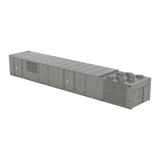
IntelliPak™ 2
Commercial Rooftop Air Conditioners
Only qualified personnel should install and service the equipment. The installation, starting up, and servicing of heating, ventilating, and air-conditioning equipment
can be hazardous and requires specific knowledge and training. Improperly installed, adjusted or altered equipment by an unqualified person could result in death or
serious injury. When working on the equipment, observe all precautions in the literature and on the tags, stickers, and labels that are attached to the equipment.
February 2023
SAFETY WARNING
RT-SVX073A-EN
Advertisement
Table of Contents

Related Manuals for Trane IntelliPak 2


Summary of Contents for Trane IntelliPak 2
- Page 1 Installation, Operation, and Maintenance IntelliPak™ 2 Commercial Rooftop Air Conditioners SAFETY WARNING Only qualified personnel should install and service the equipment. The installation, starting up, and servicing of heating, ventilating, and air-conditioning equipment can be hazardous and requires specific knowledge and training. Improperly installed, adjusted or altered equipment by an unqualified person could result in death or serious injury.
- Page 2 (HCFCs). Not all refrigerants containing these compounds bump cap, fall protection, electrical PPE and arc have the same potential impact to the environment. Trane flash clothing). ALWAYS refer to appropriate advocates the responsible handling of all refrigerants-...
- Page 3 Copyright regulations. This document and the information in it are the property of Trane, and may not be used or reproduced in whole or in Overview of Manual part without written permission. Trane reserves the right to revise this publication at any time, and to make changes to...
-
Page 4: Table Of Contents
Table of Contents Model Number Description ....7 Roof Curb and Ductwork....25 Pitch Pocket Location. - Page 5 Table of Contents Ventilation Override Module EXV Control (Electronic Expansion (VOM) ....... 59 Valve) .
- Page 6 Microchannel Condenser Coil Repair and Trane Startup Checklist ....166 Replacement......187 Critical Control Parameters and Dry Bulb Final Process .
-
Page 7: Model Number Description
Model Number Description DIGIT 1: Unit Type DIGIT 10, 11 — Design Sequence DIGIT 15 — Supply Fan Motor Selection S = Self-Contained (Packaged Rooftop) F = 15 hp G = 20 Hp Digit 2 — Unit Function DIGIT 12 — Unit Configuration Selection H = 25 Hp J = 30 Hp 1 = One-Piece Unit w/o Blank Section... - Page 8 Model Number Description DIGIT 18 — Relief/Return Fan Motor DIGIT 22 — Damper Option DIGIT 28 — Efficiency, Capacity, and Drain Selection Pan Option 0 = None 0 = Standard A = Standard Evap Coil w/ Stainless Steel Drain D = 7.5 Hp 1 = Low Leak Damper(s)-AMCA Class 2, 10cfm/ft 2 = Ultra Low Leak Damper(s)-AMCA Class 1, E = 10 Hp...
- Page 9 Model Number Description DIGIT 34 — Module Options 0 = None 1 = Modbus® 2 = Modbus® and Ventilation Override 3 =Air-Fi 4 = AirFi and Ventilation Override D = Ventilation Override F = LonTalk® L = LonTalk® and Ventilation Override M = BACnet®...
-
Page 10: General Information
S_HN units is available from output will stay at 100% during the MWU mode. When the Trane. The roof curb kit must be field assembled and MWU setpoint is reached and the heat mode is terminated,... -
Page 11: Vzh Variable Speed Compressors
General Information temperature decreases to approximately 181°F. Rapid come equipped with a protection module that monitors cycling, loss of charge, abnormally high suction phase loss, phase sequencing and motor temperature. temperatures, or the compressor running backwards could VZH Variable Speed Compressors cause the thermostat to open. -
Page 12: Pre-Installation
Pre-Installation Unit Inspection Repair Notify the appropriate sales representative before To protect against loss due to damage incurred in transit, arranging unit installation or repair. perform inspection immediately upon receipt of the unit. Important: Do not repair unit until the damage has been Exterior Inspection inspected by the carrier’s representative. -
Page 13: Installation Checklist
Pre-Installation Installation Checklist Unit Rigging and Placement (Two-piece —addition to General Checklist) General Checklist (Applies to all units) ☐ First, rig and set the low side unit on the roof curb The checklist listed below is a summary of the steps (aligned with return end). -
Page 14: Gas Heat Units
Pre-Installation ☐ Inspect all control panel components and tighten any ☐ Install the factory-supplied, 3-way modulating valve. loose connections. ☐ Complete the valve actuator wiring. ☐ Connect properly sized and protected power supply Steam Heat wiring to a field supplied/installed disconnect and the unit (copper wiring only to the unit). -
Page 15: Dimensional Data
Dimensional Data Figure 1. Unit top/left view Detail A 1-1/4 NPT. DRAIN 2X TYP. LEFT & RIGHT SIDES OF UNIT Table 2. Unit dimensions (in.)—ONE-PIECE unit —WITHOUT energy recovery wheel Return Exhaust Lifting Lug Locations Unit Height Unit Width Blank Condenser Tons Unit Dimensions... - Page 16 Dimensional Data Table 2. Unit dimensions (in.)—ONE-PIECE unit —WITHOUT energy recovery wheel (continued) Return Exhaust Lifting Lug Locations Unit Height Unit Width Blank Condenser Tons Unit Dimensions Air Handler Side Section Side 120-150 4 ft 577 2/16 197 1/16 269 6/16 63 2/16 139 13/16 143 8/16...
- Page 17 Dimensional Data Table 4. Unit dimensions (in.)—TWO-PIECE unit —WITHOUT energy recovery wheel (continued) Return Exhaust Unit Height Unit Width Blank Tons Section None 139 13/16 143 8/16 103 12/16 97 9/16 103 7/16 29 3/16 4 ft 139 13/16 143 8/16 103 12/16 97 9/16 103 7/16...
- Page 18 Dimensional Data Table 6. Downflow/horizontal airflow configuration dimensions (in.) without energy recovery wheel (ERW) DOWNFLOW Opening Dimensions Blank Tonnage Return Opening-with or without Releif Fan Return Opening-with Return Fan Gas Heat Section None None 14 13/16 8 14/16 48 3/16 121 15/16 14 13/16 42 14/16...
- Page 19 Dimensional Data Table 7. Downflow/horizontal airflow configuration dimensions (in.) with energy recovery wheel DOWNFLOW Opening Dimensions Blank Return Opening-with or without Relief Return Opening- Tonnage Supply Opening Section Heat with Return Fan Y1 W1 L1 None None 82 3/16 8 14/16 49 10/16 121 15/16 N/A N/A N/A N/A...
-
Page 20: Electrical Entry Details
Dimensional Data Electrical Entry Details Figure 2. Electrical entry details/bottom view 60 3 Bottom View 53 11 81 1 51 5 71 1 61 3 Outside edge of base rail External customer Ø1 connection points Ø1 1 Service lights Ø customer supplied Ø3 power service... -
Page 21: Minimum Required Clearance
Dimensional Data Minimum Required Clearance Figure 3. Minimum required clearance Cond R AH R Blank Section Condenser Fltr Outside Fltr Option Option As Req. Ctrl Box Final Filters L&R Relief Filters RBox Heat CBox As Req. Rtn/Rlf Rtn/Rlf Fltr Heat Outside L&R Fltr... -
Page 22: Weights
Weights shown represent approximate minimum operating weights. To calculate weight for a specific unit configuration, utilize TOPSS or contact the local Trane sales representative. Weight outputs have a + 10% accuracy. ACTUAL WEIGHTS ARE STAMPED ON THE UNIT NAMEPLATE. - Page 23 Weights Table 10. Component weights (continued) Weight Weight Weight Weight Weight Size Size Size Size Size Exhaust / Return VFD (50 hp and below) Exhaust / Return VFD (60-100 hp) Exh / Rtn Fan Motor - 7.5 hp Exh / Rtn Fan Motor - 10 hp Exh / Rtn Fan Motor - 15 hp Exh / Rtn Fan Motor - 20 hp Exh / Rtn Fan Motor - 25 hp...
- Page 24 Weights Table 11. Roof curb weights Energy Blank One-Piece Two-Piece Tonnage Recovery Section Unit Unit Wheel None 1055 90-105 4 ft 1136 90-105 8 ft 1069 1217 90-105 None 1093 1240 90-105 4 ft 1174 1321 90-105 8 ft 1401 90-105 None 1040...
-
Page 25: Installation
Return Fan Step-by-step curb assembly and installation instructions ship with each Trane accessory roof curb kit. Follow the instructions carefully to assure proper fit-up when the unit is set into place. Note: To assure proper condensate flow during operation, the unit (and curb) must be as level as possible. - Page 26 Installation Figure 5. Pitch pocket location Roof Curb Pitch Pocket Roof Curb Pitch Pocket Table 12. Pitch pocket dimensions (in.) One-Piece Two-Piece One or Two -Piece Tonnages 113.8 129.9±1 68.875 73.875 78.875 131.8 147.9±1 68.875 73.875 78.875 120,130,150 140.8 156.9±1 68.875 73.875 78.875...
-
Page 27: Field Converting Horizontal Ductwork
Installation Field Converting Horizontal Ductwork (Supply or Return) from Right to the Left Side Figure 6. Ductwork conversion Panel 2 Door Panel 1 Field Converted Header (Left Side Hz) Header Right Side Left Panel 2 Side Right Header Side Post Door Panel 1 Left... - Page 28 Installation Figure 7. Ductwork conversion Hz Return & Supply Gasketing Application Details Hz Supply or Return Header No Gasket Required Vertical Support Vertical Duct Align Gasket Adapter Channel With Vertical Support Vertical Support Skin Edge Vertical Adapter Gasket Bottom Horizontal 1/8”...
-
Page 29: Unit Rigging And Placement
Installation Figure 8. Ductwork conversion 1. To configure the unit Center-of-Gravity, utilize Trane Select Assist or contact the local Trane sales office. Vertical Support/Base Rail Bottom Gasket Application Details 2. Attach adequate strength lifting slings to all lifting lugs. The figures beginning with Figure 10, p. - Page 30 Installation Figure 10. Typical unit rigging—one-piece unit with three lifting lugs per side 24 ft min Turnbuckle or Chain Adjustment for each lug One piece unit with three lifting lugs per side Note: Turnbuckle or chain adjustment required for each lifting point. RT-SVX073A-EN...
- Page 31 Installation Figure 11. Typical unit rigging—one piece unit with four lifting lugs per side 20 ft min 15 ft min Turnbuckler or Chain Adjustment for each lug Note: Turnbuckle or chain adjustment required for each lifting point. RT-SVX073A-EN...
- Page 32 Installation Figure 12. Typical unit rigging—two-piece unit with two lifting lugs per side 12 ft min 12 ft min Air handler with two lifting lugs per side Turnbuckle or Chain Adjustment for each lug Condenser with two lifting lugs per side Note: Turnbuckle or chain adjustment required for each lifting point.
-
Page 33: Air-Cooled Condensers-Two-Piece
Installation Figure 13. Typical unit rigging—two-piece unit with three lifting lugs per air handler side 24 ft min 12 ft min Air handler with three lifting lugs per side Turnbuckle or Chain Adjustment for each lug Condenser with two lifting lugs per side Note: Turnbuckle or chain adjustment required for each lifting point. - Page 34 Installation Figure 14. (1) Protection box removal/(2) rail Figure 15. (3) Side and top filler panel removal/(4) connector installation position high side installation preparation Filler panel shipping position Filler panel Top cover shipping position shipping position Rail connector shipping position Note: Remove the filler panels and top cover before putting the Indoor and Outdoor sections together and screw to both Indoor and Outdoor panels on each side as shown in fig (6).
- Page 35 Installation Figure 16. (5) Connected tubes/(6) install panels RT-SVX073A-EN...
-
Page 36: Tubing And Wiring Connections
Installation Figure 17. Refrigeration diagram Schrader Valve Manual shuto valve Hotgas bypass valve Electronic expansion valve Cap & Schrader Solenoid valve Hot gas Reheat Valve Condenser Coil Circuit 2 Liquid Line Suction Line Hot Gas Reheat Hot gas Bypass Suction Line Liquid Line Condenser Coil Circuit 1 Tubing and Wiring Connections... - Page 37 Installation to 500 microns or less. To establish that the unit is leak- block inside the electric Junction Box or inside the free, use a standing vacuum test. The maximum extended casing section. allowable rise over a 15 minute period is 200 microns. If Note: For 8' extended casing units, remove the panel the rise exceeds this, there is either still moisture in the (this panel weighs approximately 60 pounds)
-
Page 38: General Installation Requirements
Installation Figure 19. Wire routing and connections Electric Heat Power Wires - Routed through the hole Electric Heat at the air handler side end wall. Route wires one by one and connect to the electric heat terminal block. Terminal Block Electric Heat Control Wires - Routed through the hole at the air handler side end wall. -
Page 39: Main Electrical Power
Installation ☐ Remove the shipping hold-down bolts and shipping ☐ Install the factory-supplied, 3-way modulating valve. channels from the supply and relief fans with spring ☐ Refer to the schematic to complete the valve actuator isolators. wiring. ☐ Check all supply and relief fan spring isolators for Steam Heat proper adjustment. -
Page 40: Units With Gas Furnace
Installation Spring Isolators Figure 21. Condensate trap installation Spring isolators for the supply and/or exhaust fan are 1-1/4” NPT Base rail female connection shipped with the isolator adjusting bolt backed out. Field Field supplied adjustment is required for proper operation. shows isolator condensate piping locations. - Page 41 Installation Figure 22. Outside air sensing kit Sensor Sensor mounting screws Sensor mounting slotted bracket 0.188in OD tubing L bracket Figure 23. Outside air tubing schematic Fresh Air Fresh Air Transducer Transducer Upper Upper Left side Left side Flow Flow High High Ring...
-
Page 42: Gas Heat Units
Installation 100 ft.) or 3/8" (length greater than 100 ft.) O.D. location inside the building. This location should be the pneumatic tubing for the space pressurization control to largest open area that will not be affected by sudden the bottom fitting. static pressure changes. - Page 43 Installation WARNING incorrect gas pressure, which can cause erratic operation due to gas pressure fluctuations as well as Explosion Hazard! damage the gas valve. Oversizing the regulator will Failure to properly regulate pressure could result in a cause irregular pulsating flame patterns, burner rumble, violent explosion, which could result in death, serious potential flame outages, and possible gas valve injury, or equipment or property-only-damage.
- Page 44 Installation Table 13. Sizing natural gas pipe mains and branches Gas Input (Cubic Feet/Hour) Gas SupplyPipe Run (ft) 1¼" Pipe 1½" Pipe 2" Pipe 2½" Pipe 3" Pipe 4" Pipe 1,060 1,580 3,050 4,860 8,580 17,500 1,090 2,090 3,340 5,900 12,000 1,680 2,680...
- Page 45 Installation Figure 27. Two-stage and modulating natural gas Table 16. Gas heat inlet sizes train for 850, 1100 MBH heaters Standard Gas Heat Input (MBh) Gas Heat Inlet Sizes (in.) Ingnition 1 1/4 transformer Manual 1100 1 1/4 shut-off valve 1800 1 1/2 2500...
- Page 46 Installation Flue Assembly Installation Figure 29. Flue assembly 1. Locate the collapsed flue assembly in the compartment above the gas heat controls by removing the panel screws. The assembly is secured by screws up through the roof of the gas controls compartment roof. 2.
-
Page 47: General Coil Piping And Connection Recommendations
Installation Table 17. Gas heat piping penetration measurements Condensate Drain Gas Connection, Gas Connection, Gas Flue Outlet Horizontal Base Horizontal Distance Energy Mist Elim to Flue C/ Recovery Unit End to Hole C/L Unit End to Hole C/L Wheel Heat (ERW) (MBH) Tons... - Page 48 Installation illustrated in Figure 31, p. installation and operation of the “wet heat” system. Figure 33, p. 50 illustrates the recommended piping Use the following guidelines to enhance both the configurations for the steam coil.Table 18, p. 49 lists the installation and operation of the “wet heat”...
- Page 49 Installation 33, p. 50 illustrates the recommended piping Table 18. Hot water and steam coil connection sizes configuration for the steam coils. Hot Water Coil Steam Coil a. Install a strainer in each return line before the Sup- Sup- Unit Drain/ steam trap.
-
Page 50: Disconnect Switch With External
“OFF” - Indicates that the disconnect switch is open, or other energy storing components provided by interrupting the main power supply to the unit controls. Trane or others, refer to the appropriate • “RESET/LOCK” - Turning the handle to this position manufacturer’s literature for allowable waiting periods... -
Page 51: Electric Heat Units
Installation Figure 34. Disconnect switch external handle Use the information provided in Service Sizing data and the “Power Wire Sizing & Protection Device Equations,” to determine the appropriate wire size and Maximum Over current Protection for the heaters/unit. Note: Each power supply must be protected from short circuit and ground fault conditions. -
Page 52: Electrical Service Sizing
Installation Figure 35. Typical field power wiring (front view) Front View Control Box Field Supplied Survice Over Current Protection 1QB1 or 1XD1 Pitch Pocket Pitch Pocket 3-Wire Power Supply+Ground Electric Heat Control Panel Gas Heat Control Panel Steam or Hot Water Control Panel Condenser Section Heat Control Box... - Page 53 Installation Set 2: Rooftop units with Electric Heat Select a fuse rating equal to the MOP value. If the MOP value does not equal a standard fuse size as listed in NEC To arrive at the correct MCA and MOP values for these 240-6, select the next lower standard fuse rating.
- Page 54 Installation Table 22. Electrical service sizing data (continued) Compressor Nominal Voltage Nom Tons 460 V 575 V 380 V No per Unit Size RLA (ea.) LRA (ea.) RLA (ea.) LRA (ea.) RLA (ea.) LRA (ea.) 44.6 35.7 26.2 20.9 26.4 36.1 28.9 36.4...
- Page 55 Installation Table 23. Electrical service sizing data—motors — air-cooled and evaporative condensing Fixed Speed Variable Speed Standard Ambient Low Ambient Standard or Low Ambient No of Nominal Tonnage Fans Voltage 90, 105 16.2 13.2 12.4 14.8 12.5 10.8 14.3 120, 130, 150 21.6 17.6 20.4...
- Page 56 Installation Table 26. Transformer 1 and 2 primary amps Voltage Nom Tons 90–150 Table 27. Voltage utilization range Unit Voltage Range 460/60/3 414-506 575/60/3 517-633 380/50/3 342-418 Table 28. Electrical service sizing data—energy recovery wheel motor Voltage Nom Tons Unit Function 1 (Low CFM ERW) 90-120 0.90...
-
Page 57: Field Installed Control Wiring
Installation Field Installed Control Wiring 2. Ensure that the AC control wiring between the controls and the unit's termination point does not exceed three The Symbio™ 800 must have a mode input in order to (3) ohms/conductor for the length of the run. operate the rooftop unit. -
Page 58: Constant Volume Zone Panel (Baysens108*)
This electronic analog sensor features single setpoint capability and timed override with override cancellation. It – Occupied/Unoccupied/VAV box output - Energized is used with a Trane Integrated Comfort™ system. Refer to – VOM Relay - Energized (if so equipped) Table 31, p. 60 for the Temperature vs. -
Page 59: (Vom)
Installation – Supply Fan - Off – Heat - All heat stages off; Mod Heat output at 0 – Supply Fan VFD - Closed/Min (if so equipped) – Exhaust Fan - Off; Exhaust Dampers Closed (if so – Occupied/Unoccupied/VAV box output - equipped) Deenergized –... -
Page 60: Emergency Stop Input
Installation – Exhaust Bypass Dampers - Open (if so equipped) made from Keystone Carbon D97 material with a 1 degree Centigrade tolerance. • PURGE sequence “D” Table 31. Temp vs. resistance Possibly this sequence could be used for purging the air out of a building before coming out of Resistance (in. - Page 61 Installation Automation System control output. The relay’s contacts schematics supplied with the unit for proper connection must be rated for 12 ma @ 24 VDC minimum. Refer to terminals in the unit control panel. RT-SVX073A-EN...
-
Page 62: Unit Startup
Unit Startup Sequence of Operation must be set to “True” to allow this function to operate. Mechanical cooling (DX) is available for Rapid Restart if the NOTICE Outdoor Air Temperature is above the Low Ambient Lockout setpoint. Compressor Failure! After power-up start delay is satisfied, the unit will override Failure to follow instruction below could result in all other forms of time delays (i.e. -
Page 63: Sensors
Field installed wired Unoccupied Any State Zero Unoccupied sensors are available from Trane and many other sources. In every case, the correct type of sensor must be used. Unoccupied Any State Not Zero... -
Page 64: Operating Modes
Unit Startup Cool flow control is enabled, operating mode transitions, and capacity control enables. Cool mode is reported when the control objective is to provide cooling to maintain building comfort. Direct • Single Zone VAV (Space Temperature) expansion cooling is the primary cooling source. Cool Single Zone VAV control units will also accept a mode is also reported when Economizer cooling, Maximum Heat command via Heat Cool Mode... -
Page 65: Unit Sub-Modes
Unit Startup Run Inhibit displayed when the circuit is shutting down on a latching diagnostic. The unit is currently being inhibited from starting and running. For example, if a Power Up Delay timer is Unit Sub-Modes preventing the unit startup, Power Up Delay Inhibit (Min: Sec) will be listed with the remaining minutes and seconds Morning Warm Up to expire. -
Page 66: Supply Fan Control
Unit Startup Space temperature control units must be in Cool or Auto type allows modulating air flow. Else if the heat type mode to allow Pre Cool operation. Discharge air control requires full air flow, Maximum Heat is reported. units also evaluate Pre Cool operation on transition from When the space temperature rises above the Daytime Off/Shutdown to Occupied. -
Page 67: Supply Fan Vfd Bypass Control
Unit Startup Exiting Supply Fan VFD Bypass Mode • Constant Volume units always run the fans at 100% after being proved On. The command is 0% while • The user will not be allowed to remove the unit from an waiting on proving. -
Page 68: Minimum Ventilation Control
Unit Startup 3. External fan control in bypass mode is supported. An settings to linearize damper position with the fan curve. external Supply Fan Speed Setpoint value = 0% will Table 34, p. 68 for additional information. turn the fan Off, and any value > 0 will turn the fan On. Outdoor Air Minimum Position Control The Supply Fan Speed Status always reports 100% speed during active supply fan bypass operation. -
Page 69: Relief Fan And Space Static Pressure
Unit Startup Table 34. Outdoor air damper minimum ventilation control methods (continued) Traq Outdoor Air Flow Description Outdoor Air Damper Demand Control Compensation Ventilation Controlling Setpoints Disabled Enabled/Active Disabled Outdoor Air Damper Setpoint: Minimum Position is reset Economizer Minimum based on supply fan speed. Position Setpoint Active Settings: Design Min OA Damper Pos... -
Page 70: 0-25% Motorized Outdoor Air
Unit Startup Space Static Pressure Control without • Ventilation Override Mode Statitrac™ • Emergency Override If Statitrac™ is not installed, or the space static pressure • External Capacity Control sensor has failed, space static pressure control without • Return/Relief fans with and without bypass Statitrac becomes active. - Page 71 Unit Startup Figure 37. Energy recovery wheel operation Outside Air Bypass Damper Outside Air Intake Damper (Mist Eliminator not shown) Exhaust Air, Leaving Energy Recovery Wheel, Path to Exhaust Fan Energy Recovery Wheel Conditioned Outside Air Unit Return Path to Filters & Coil Airflow ERW Unit Entering Air (Mixed Return Air &...
-
Page 72: Availability
Unit Startup Figure 38. Energy recovery wheel economizer operation Outside Air Intake Damper Outside Air Bypass Damper (Mist Eliminator not shown) Conditioned Path to Outside Air Filters & Coil Exhaust Air Path to Exhaust Fan Unit Return Path to Airflow Filters &... -
Page 73: Energy Wheel Frost Avoidance W/Preheat (Optional)
Unit Startup Recovery Temperature Sensor value falls below the The Leaving Recovery Temp Sensor is installed in the Recovery Frost Avoidance Setpoint. The Leaving Recovery leaving air stream on the relief-fan side of the energy Temperature Sensor is installed in the leaving air stream on wheel. -
Page 74: Control
Unit Startup “in-control” when supply fan and return fan are proven. limited by Return Plenum Static Pressure High Limit control Supply fan operation always starts before return fan. to prevent potential equipment cabinet damage. Return Plenum Pressure Sensor Proving Return Fan Space Pressure Critical Low Limit The return plenum static pressure sensor is proven in the return fan startup sequence. -
Page 75: Space Temperature Control
Unit Startup Duct Static Pressure High Limit cooling when heat capacity is no longer required. Supply Air Tempering is disabled by default. The controller operates the supply fan to maintain duct Multi Zone-VAV equipment allows supply air tempering static pressure below the Duct Static Pressure High Limit when equipped with Modulating Gas, Ultra Modulating setpoint. -
Page 76: Space Temperature Control Units
Unit Startup Figure 40. Auto changeover logic Space Temperature must rise above the active space Cool Setpoint before the controller can change to Cool. 3. The controller switches to Heat (from cool) after the error integrator exceeds 900°F seconds or Space Temperature <= (Heat Setpoint –... -
Page 77: Compressor Staging And Timers
Unit Startup economizer and DX cooling are active. If actively request staging to occur beyond 3 minutes but the time economizing, outdoor air damper is 100% and supply fan span from one stage turning ON(OFF) until the next speed reaches 100% then DX cooling will be added if the compressor stage turning ON(OFF) will be no less than the unit is not satisfying space cooling requirements. -
Page 78: Compressor Protections
Unit Startup Compressor Lockout and Inhibit balanced staging rules will be used to process the next staging request. In all cases of Lockouts, Inhibits, and Limits (Compressor Minimum OFF Time is not considered a lockout or inhibit) Compressor Staging with Variable Speed Alternate Staging Sequences will be substituted. - Page 79 Unit Startup These protections typically involve reducing, if not Low Compressor Suction Pressure Limit only applies to completely removing, one or more compressors from circuits which have more than 1 compressor installed. This operation on a given refrigeration circuit. There are function prevents the addition of circuit capacity any time basically two types.
- Page 80 Unit Startup compressors. This circuit-level feature applies when the pressure. This will reduce the variable speed compressor suction saturated temperature exceeds the compressor motor current thus preventing an A49 Speed Limit VFD trip. operating threshold limit for suction saturated temperature. This function works in concert with Current Limit Staging Inhibit control action de-energizes the variable speed Command which can subtract, hold or allow adding...
-
Page 81: Hot Gas Bypass
Unit Startup Low Ambient Operation HGBP valve calibration (also known as overdrive closed) procedure is initiated in the following circumstances: Units configured with Low Ambient Operation use a modulating condenser fan for the first stage. • Whenever the unit controller is power cycled. This is under the control of the unit controller software, as part Hot Gas Bypass of the software startup procedure. -
Page 82: Economizing
Unit Startup Functional Description Note: EXV calibration time is used for both HGBP and EXV valve calibration. EXV Calibration • Whenever the EXV electronic controller is power An EXV Calibration (also known as overdrive closed) cycled. The EXV electronic controller does this procedure will be initiated in the following circumstances: automatically. -
Page 83: Outdoor Air Damper Fault Detection And Diagnostics (Fdd)
Unit Startup Table 37. Economizer high-limit decision methods Outdoor Air Temperature < Economizer Outdoor Air Enable Setpoint – 5°F Enable Fixed Dry Bulb Outdoor Air Temperature > Economizer Outdoor Air Enable Setpoint Disable Outdoor Air Enthalpy < Reference Enthalpy Setpoint – 3 BTU/lb Enable Outdoor Air Temperaure <... -
Page 84: Occupied
Unit Startup Dehumidification Control - Unoccupied Mode Status is not Cool, or a sensor required for dehumidification control is invalid. Unoccupied Dehumidification control sequence of operation is the same for all unit types when the controller Dew Point is in unoccupied mode, hot gas reheat is configured, and If space dew point is greater than the space dew point the unoccupied dehumidification feature is enabled. - Page 85 Unit Startup Failure to Start configured; otherwise, the supply fan operates at full capacity in all other heat operating mode If pre-purge is not detected within 60 seconds, after All heat types, when the control terminates heating request for Stage 1 or minimum fire, it indicates a problem capacity or exists a heating mode;...
-
Page 86: Unoccupied Cooling
Unit Startup Electric Heat Protection Unoccupied Cooling Mechanical Enable and Unoccupied Cooling Economizing Enable are settings to enable or There are three automatic high temperature limit switches disable cooling in unoccupied mode. that will trip when exposed to a high temperature. They will reset automatically once the temperature drops into an Unoccupied Heating acceptable range. - Page 87 Unit Startup Table 39. External supply fan control points Table 41. External relief fan control points (continued) Object Name Description Object States or values Object Description Name Exhaust Fan Speed Enables Relief fan 0 = Disable Setpoint Enable speed setpoint control 1 = Enable Supply Fan Supply fan speed is being increased or decreased due...
-
Page 88: Overrides
Unit Startup Emergency Stop • Outdoor Air Flow Compensation Enable = Disable Morning Warm Up, Pre-Cool, Night Purge, Unoccupied, Symbio 800 accepts a dry contact closure input suitable for and Off modes of operation will override damper minimum customer connection to request Stop or Auto modes from position to 0%. - Page 89 Unit Startup compressors and condenser fans, and all other When any VOM Mode (A, B, C, D, E) input is activated or components not directly controlled via VOM events, are closed, the VOM mode of operation will begin in less than disabled during the ventilation operation.
- Page 90 Unit Startup Table 43. Ventilation override mode (continued) VOM Input OUTPUT OPERATION Heat Cool Mode Status Mode E Supply fan On/Duct Static Pressure Control Fan Only (Purge with Duct Static Pressure Control) Outdoor air damper Open Relief fan / Relief damper On/Open Return Fan/Relief Damper On/Open...
-
Page 91: Limits
If both points are True (locked out) at the same time, both the setpoint can be set to 6.0 IWC which is above the will be honored. Trane Graphical Programming (TGP2) can pressure transducers range. No manual calibration is be used to control these points. - Page 92 Unit Startup WARNING connected for clockwise rotation with the incoming power supply phased as A, B, C. Hazardous Voltage! Proper electrical supply phasing can be quickly determined Failure to disconnect power before servicing could and corrected before starting the unit by using an result in death or serious injury.
- Page 93 Unit Startup Verifying Proper Fan Operation WARNING Live Electrical Components! WARNING Failure to follow all electrical safety precautions when Hazardous Service Procedures! exposed to live electrical components could result in Failure to follow all precautions in this manual and on death or serious injury.
- Page 94 Unit Startup b. Touch Manual Control Settings in the Settings 4. The above procedure can be followed for testing and screen. setup of relief fans and condenser fans. Note: Changes to the unit’s design relief airflow rating is modified at the user interface by adjusting the Relief Fan Maximum Speed Setpoint located under the Service Settings menu.
- Page 95 Unit Startup WARNING WARNING Hazardous Voltage! Live Electrical Components! Failure to disconnect power before servicing could Failure to follow all electrical safety precautions when result in death or serious injury. exposed to live electrical components could result in death or serious injury. Disconnect all electric power, including remote disconnects before servicing.
- Page 96 Unit Startup Exhaust Airflow Measurement (Optional) is less than design and airflow is too high. If the amperage is below the motor nameplate value, static WARNING pressure may be too high and CFM may be too low. To determine the actual CFM (± 5%): Hazardous Voltage! a.
-
Page 97: Performance Data
Unit Startup Performance Data Supply Fan Figure 43. Supply fan performance LOW CFM (25") Figure 44. Supply fan performance STANDARD CFM (36")- 90-105 tons RT-SVX073A-EN... - Page 98 Unit Startup Figure 45. Supply fan performance LOW CFM (32") Figure 46. Supply fan performance STANDARD CFM - 120-150 tons (40") RT-SVX073A-EN...
-
Page 99: Airside Pressure Drop - Standard
Unit Startup Airside Pressure Drop — Standard Evaporator Coil Figure 47. Wet airside pressure drop at 0.075 lb./cu. ft.— 90-150 tons standard evaporator coil Figure 48. Dry airside pressure drop at 0.075 lb./cu. ft.— 90-150 tons standard capacity evaporator coil RT-SVX073A-EN... -
Page 100: Evaporator Coil
Unit Startup Figure 49. Wet airside pressure drop at 0.075 lb./cu. ft.— 90-130 tons high capacity evaporator coil Figure 50. Dry airside pressure drop at 0.075 lb./cu. ft.—90-130 tons high capacity evaporator coil RT-SVX073A-EN... -
Page 101: Relief Fan
Unit Startup Relief Fan Figure 51. Relief fan performance LOW CFM - 90 tons (25" Fan) Figure 52. Relief fan performance STANDARD CFM—90 tons; LOW CFM—105-150 tons (28") RT-SVX073A-EN... -
Page 102: Return Fan
Unit Startup Figure 53. Relief fan performance standard CFM —105-150 tons (32") Return Fan Figure 54. Return fan performance LOW CFM 90-150 tons (36.5") RT-SVX073A-EN... - Page 103 Unit Startup Figure 55. Return fan performance STANDARD CFM - 90-105 tons (40") Figure 56. Return fan performance STANDARD CFM—120-150 tons (44”) RT-SVX073A-EN...
-
Page 104: Drops
Unit Startup Component Static Pressure Drops Table 45. Component static pressure drops (in. H Evaporator Coil (Dampers wide open) High Capacity Outside Air Standard Reheat Coil Return Tons Damper Econo Traq Damper Damper 16000 0.13 0.17 0.22 0.04 0.06 0.11 0.19 20000 0.15... - Page 105 Unit Startup Table 46. Component static pressure drops (in. H Electric Gas Heating Hydronic Heating Coil Data Heating High Heat Tons (Hz) All Low Heat Medium Heat Hot Water Coil Steam Coil High High 16000 0.01 0.01 0.02 0.01 0.04 0.03 0.07 0.13...
- Page 106 Unit Startup Table 47. Energy recovery wheel component static pressure drops — low CFM Outside Air Outside Air Relief Air Bypass Relief Air Bypass Bypass Damper Nom Tons Bypass Damper Damper Open Damper Closed Open Closed Low CFM Energy Recovery Wheel 8000 0.07 0.78...
- Page 107 Unit Startup Table 47. Energy recovery wheel component static pressure drops — low CFM (continued) Outside Air Outside Air Relief Air Bypass Relief Air Bypass Bypass Damper Nom Tons Bypass Damper Damper Open Damper Closed Open Closed Low CFM Energy Recovery Wheel 9000 0.09 0.71...
- Page 108 Unit Startup Table 48. Energy recovery wheel component static pressure drops — standard CFM (continued) Outside Air Outside Air Relief Air Bypass Relief Air Bypass Bypass Damper Nom Tons Bypass Damper Damper Open Damper Closed Open Closed Standard CFM Energy Recovery Wheel 10000 0.10 0.56...
- Page 109 Unit Startup Table 49. Energy recovery wheel component static pressure drops — dampers (continued) Return Damper, Econo Damper, Tons ERW only ERW only 23000 0.25 0.21 26000 0.32 0.27 30000 0.42 0.36 35000 0.57 130-150 40000 0.75 0.65 45000 0.96 0.83 50000 1.19...
-
Page 110: Pressure Curves
Unit Startup Pressure Curves (60 Hz) Air-Cooled Condensers Figure 57. Operating pressure curve (all comp. and cond. fans per ckt. on)—90 tons std. capacity Figure 58. Operating pressure curve (all comp. and cond. fans per ckt. on)—90 tons high capacity RT-SVX073A-EN... - Page 111 Unit Startup Figure 59. 90 ton eFlex variable speed—circuit 1 and circuit 2 operating pressure curve (compressor at 100% and all condenser fans ON) (standard capacity) 90 Ton eFlex Circuit 1, 60Hz, Std Capacity F Ambient F Ambient F Ambient F Ambient F Ambient Suc on Pressure, PSIG...
- Page 112 Unit Startup Figure 60. 90 ton eFlex variable speed—circuit 1 and circuit 2 operating pressure curve (compressor at 100% and all condenser fans ON) (high capacity) 90 Ton eFlex Circuit 1, 60Hz High Capacity F Ambient F Ambient F Ambient F Ambient F Ambient Suc on Pressure, PSIG...
- Page 113 Unit Startup Figure 61. Operating pressure curve (all comp. and cond. fans per ckt. on)—105 tons std. capacity Figure 62. Operating pressure curve (all comp. and cond. fans per ckt. on)—105 tons high capacity RT-SVX073A-EN...
- Page 114 Unit Startup Figure 63. 105 ton eFlex variable speed—circuit 1 and circuit 2 operating pressure curve (compressor at 100% and all condenser fans ON) (standard capacity) 105 Ton eFlex Circuit 1, 60Hz, Std Capacity F Ambient F Ambient F Ambient F Ambient F Ambient Suc on Pressure, PSIG...
- Page 115 Unit Startup Figure 64. 105 ton eFlex variable speed—circuit 1 and circuit 2 operating pressure curve (compressor at 100% and all condenser fans ON) (high capacity) 105 Ton eFlex Circuit 1, 60Hz High Capacity F Ambient F Ambient F Ambient F Ambient F Ambient Suc on Pressure, PSIG...
- Page 116 Unit Startup Figure 65. Operating pressure curve (all comp. and cond. fans per ckt. on)—120 tons std. capacity Figure 66. Operating pressure curve (all comp. and cond. fans per ckt. on)—120 tons high capacity RT-SVX073A-EN...
- Page 117 Unit Startup Figure 67. 120 ton eFlex variable speed—circuit 1 and circuit 2 operating pressure curve (compressor at 100% and all condenser fans ON) (standard capacity) 120 Ton eFlex Circuit 1, 60Hz, Std Capacity F Ambient F Ambient F Ambient F Ambient F Ambient Suc on Pressure, PSIG...
- Page 118 Unit Startup Figure 68. 120 ton eFlex variable speed—circuit 1 and circuit 2 operating pressure curve (compressor at 100% and all condenser fans ON) (high capacity) 120 Ton eFlex Circuit 1, 60Hz High Capacity F Ambient F Ambient F Ambient F Ambient F Ambient Suc on Pressure, PSIG...
- Page 119 Unit Startup Figure 69. Operating Pressure Curve (All Comp. and Cond. Fans per ckt. on)—130 Tons Std. Capacity Figure 70. Operating Pressure Curve (All Comp. and Cond. Fans per ckt. on)—130 Tons High Capacity RT-SVX073A-EN...
- Page 120 Unit Startup Figure 71. 130 ton eFlex variable speed—circuit 1 and circuit 2 operating pressure curve (compressor at 100% and all condenser fans ON) (standard capacity) 130 Ton eFlex Circuit 1, 60Hz, Std Capacity F Ambient F Ambient F Ambient F Ambient F Ambient Suc on Pressure, PSIG...
- Page 121 Unit Startup Figure 72. 130 ton eFlex variable speed—circuit 1 and circuit 2 operating pressure curve (compressor at 100% and all condenser fans ON) (high capacity) 130 Ton eFlex Circuit 1, 60Hz High Capacity F Ambient F Ambient F Ambient F Ambient F Ambient Suc on Pressure, PSIG...
- Page 122 Figure 73. Operating pressure curve (all comp. and cond. fans per ckt. on)—150 ton std. capacity Note: Due to the variable speed fans on Evaporative Condenser units, typical operating pressure curves are not relevant. If operating pressures at certain conditions are needed, contact a local Trane sales representative. RT-SVX073A-EN...
- Page 123 Unit Startup Figure 74. 150 ton eFlex variable speed—circuit 1 and circuit 2 operating pressure curve (compressor at 100% and all condenser fans ON) (standard capacity) 150 Ton eFlex Circuit 1, 60Hz F Ambient F Ambient F Ambient F Ambient F Ambient Suc on Pressure, PSIG 150 Ton eFlex Circuit 2, 60Hz...
-
Page 124: (50 Hz) Air-Cooled Condensers
Unit Startup (50 Hz) Air-Cooled Condensers Figure 75. Operating pressure curve (all comp. and cond. fans per ckt. on)—90 tons standard capacity Figure 76. Operating pressure curve (all comp. and cond. fans per ckt. on)—90 tons high capacity RT-SVX073A-EN... - Page 125 Unit Startup Figure 77. 90 ton eFlex variable speed—circuit 1 and circuit 2 operating pressure curve (compressor at 100% and all condenser fans ON) (standard capacity) 90 Ton eFlex Circuit 1, 50Hz F Ambient F Ambient F Ambient F Ambient F Ambient Suc on Pressure, PSIG 90 Ton eFlex Circuit 2, 50Hz...
- Page 126 Unit Startup Figure 78. 90 ton eFlex variable speed—circuit 1 and circuit 2 operating pressure curve (compressor at 100% and all condenser fans ON) (high capacity) 90 Ton eFlex Circuit 1, 50Hz High Capacity F Ambient F Ambient F Ambient F Ambient F Ambient Suc on Pressure, PSIG...
- Page 127 Unit Startup Figure 79. Operating pressure curve (all comp. and cond. fans per ckt. on)—105 tons standard capacity Figure 80. Operating pressure curve (all comp. and cond. fans per ckt. on)—105 tons high capacity RT-SVX073A-EN...
- Page 128 Unit Startup Figure 81. 105 ton eFlex variable speed—circuit 1 and circuit 2 operating pressure curve (compressor at 100% and all condenser fans ON) (standard capacity) 105 Ton eFlex Circuit 1, 50Hz F Ambient F Ambient F Ambient F Ambient F Ambient Suc on Pressure, PSIG 105 Ton eFlex Circuit 2, 50Hz...
- Page 129 Unit Startup Figure 82. 105 ton eFlex variable speed—circuit 1 and circuit 2 operating pressure curve (compressor at 100% and all condenser fans ON) (high capacity) 105 Ton eFlex Circuit 1, 50Hz High Capacity F Ambient F Ambient F Ambient F Ambient F Ambient Suc on Pressure, PSIG...
- Page 130 Unit Startup Figure 83. Operating pressure curve (all comp. and cond. fans per ckt. on)—120 tons standard capacity Figure 84. Operating pressure curve (all comp. and cond. fans per ckt. on)—120 tons high capacity RT-SVX073A-EN...
- Page 131 Unit Startup Figure 85. 120 ton eFlex variable speed—circuit 1 and circuit 2 operating pressure curve (compressor at 100% and all condenser fans ON) (standard capacity) 120 Ton eFlex Circuit 1, 50Hz F Ambient F Ambient F Ambient F Ambient F Ambient Suc on Pressure, PSIG 120 Ton eFlex Circuit 1, 50Hz...
- Page 132 Unit Startup Figure 86. 120 ton eFlex variable speed—circuit 1 and circuit 2 operating pressure curve (compressor at 100% and all condenser fans ON) (high capacity) 120 Ton eFlex Circuit 1, 50Hz High Capacity F Ambient F Ambient F Ambient F Ambient F Ambient Suc on Pressure, PSIG...
- Page 133 Unit Startup Figure 87. Operating pressure curve (all comp. and cond. fans per ckt. on)—130 tons standard capacity Figure 88. Operating pressure curve (all comp. and cond. fans per ckt. on)—130 tons high capacity RT-SVX073A-EN...
- Page 134 Unit Startup Figure 89. 130 ton eFlex variable speed—circuit 1 and circuit 2 operating pressure curve (compressor at 100% and all condenser fans ON) (standard capacity) 130 Ton eFlex Circuit 1, 50Hz F Ambient F Ambient F Ambient F Ambient F Ambient Suc on Pressure, PSIG 130 Ton eFlex Circuit 2, 50Hz...
- Page 135 Unit Startup Figure 90. 130 ton eFlex variable speed—circuit 1 and circuit 2 operating pressure curve (compressor at 100% and all condenser fans ON) (high capacity) 130 Ton eFlex Circuit 1, 50Hz High Capacity F Ambient F Ambient F Ambient F Ambient F Ambient Suc on Pressure, PSIG...
- Page 136 Figure 91. Operating pressure curve (all comp. and cond. fans per ckt. on)—150 tons standard capacity Note: Due to the variable speed fans on evaporative condenser units, typical operating pressure curves are not relevant. If operating pressures at certain conditions are needed, contact a local Trane sales representative. RT-SVX073A-EN...
-
Page 137: Components
Unit Startup Figure 92. 150 ton eFlex variable speed—circuit 1 and circuit 2 operating pressure curve (compressor at 100% and all condenser fans ON) (standard capacity) 150 Ton eFlex Circuit 1, 50Hz F Ambient F Ambient F Ambient F Ambient F Ambient Suc on Pressure, PSIG 150 Ton eFlex Circuit 2, 50Hz... - Page 138 Unit Startup WARNING 5. With the outside air dampers fully closed and the supply fan operating at 100% airflow requirements, No Step Surface! measure the return static pressure at the location Failure to follow instruction below could result in determined in step 1. death or serious injury.
- Page 139 Unit Startup may need to be adjusted. Figure 94. Outside air and return air economizer assembly (with Traq™ dampers) 13. Tighten the lock nut against the swivel(s). 14. Plug the holes after the proper CFM has been established. Figure 93. Outside air and return air damper assembly TRAQ Damper Linkage Adjustment...
-
Page 140: Standard Unit With Energy Recovery
Unit Startup Standard Unit with Energy Recovery Table 51. Standard unit (no ERW) (economizer) outside air damper travel adjustment/pressure drop Wheel (inches w.c.) (continued) Economizer Damper Adjustment - ERW units 45,500 0.48 0.99 1.79 2.22 2.62 Outside & Return Air Damper Operation 42,000 0.41 0.85... - Page 141 Unit Startup WARNING The actuator will drive open and then closed to determine the new open and closed positions. Rotating Components! 6. Return the actuator control signal dial to 2-10 VDC Failure to disconnect power before servicing could Modulating input signal position. result in rotating components cutting and slashing 7.
- Page 142 Unit Startup Figure 95. IntelliPak 2 energy wheel section RT-SVX073A-EN...
- Page 143 Unit Startup RT-SVX073A-EN...
- Page 144 Unit Startup RT-SVX073A-EN...
- Page 145 Unit Startup RT-SVX073A-EN...
-
Page 146: Energy Recovery Wheel (Erw)
Unit Startup Energy Recovery Wheel (ERW) the section for service access into the return/exhaust air compartment, see “Figure 125,” p. 142. The IntelliPak™ 2 energy wheel section consists of the energy wheel cassette assembly, return air, outside air, and bypass dampers, and outside air mist eliminators. Double opposing large access doors are provided on both sides of RT-SVX073A-EN... - Page 147 Unit Startup WARNING WARNING Toxic Hazards! Rotating Components! Failure to follow instructions below could result in Failure to disconnect power before servicing could death or serious injury. result in rotating components cutting and slashing technician which could result in death or serious Do not use an energy wheel in an application where injury.
- Page 148 1. Wash the segments or the wheel in a five-percent solution of non-acid-base coil cleaner (part no. WARNING CHM00021 at your local Trane parts center) or in an Hazardous Voltage! alkaline detergent and warm water. Failure to disconnect power before servicing could 2.
- Page 149 Unit Startup units have larger sized wheels and have inner and satellite Figure 98. Segment Removal segments. The satellite segments are secured to the wheel frame by a segment retainer in the same fashion as the outer segments for the above mentioned smaller low CFM recovery wheels.
- Page 150 Unit Startup WARNING CAUTION Risk of Energy Wheel Collapsing! Sharp Edges! Failure to follow instructions below could cause the Failure to follow instructions below could result in energy wheel to collapse under the technician’s minor to moderate injury. weight which could result in severe injury. The service procedure described in this document Before laying across the energy wheel, add extra involves working around sharp edges.
- Page 151 Unit Startup frame with the screwdriver. Note: Inspect these filters monthly and clean them as necessary. 5. Reinstall forked segment retainer(s) Bearing and Motor Lubrication Note: Only applies when there is an adjacent segment in place. The wheel drive motor and wheel support shaft bearings are permanently lubricated and no further lubrication is 6.
- Page 152 Unit Startup on the belt, as a slack belt may be prone to twist. Figure 101. Link belt installation 7. Manually rotate the wheel clockwise until the linked belt ends are approximately 180° from the motor pulley location. 8. Insert the right angle belt retainer from the replacement kit at the pulley location.
-
Page 153: Compressor Startup
Unit Startup Seal Adjustment Drive Motor and Pulley Replacement WARNING WARNING Hazardous Voltage! Hazardous Voltage! Failure to disconnect power before servicing could Failure to disconnect power before servicing could result in death or serious injury. result in death or serious injury. Disconnect all electric power, including remote Disconnect all electric power, including remote disconnects before servicing. -
Page 154: Refrigerant Charging
Unit Startup Important: COMPRESSOR SERVICE VALVES MUST BE the unit control panel to stop the compressor operation. FULLY OPENED BEFORE STARTUP 11. Repeat steps 5–11 for each compressor stage and the (SUCTION, DISCHARGE, AND LIQUID appropriate condenser fans. LINE). Refrigerant Charging 3. -
Page 155: Compressor Crankcase Heaters
Make sure and keep the The scroll compressor uses Trane OIL00079 (one quart sound enclosure installed at all times other than servicing. container) or OIL00080 (one gallon container) without Important: Variable speed scroll compressors sound substitution. - Page 156 Unit Startup Table 56. Staging sequence 90 ton standard and hi Table 59. Compressor data (fixed speed capacity compressors) (continued) Stage Comp 1A Comp 1B Comp 2A Comp 2B Compressors Unit Comp Comp Comp Comp Comp Comp Size 120 Ton Std &...
- Page 157 Unit Startup Table 60. eFlex™ staging sequence and compressor data (continued) 2520 5460 1500 6000 2520 5280 1500 6000 2520 4740 90 Ton eFlex™ Variable Speed Compressor High Capacity Evaporator Stage VZH Min Speed VZH Max Speed 1A: VZH 170 1B: CSHL 169 2A: CSHL 169 2B: CSHL 169...
-
Page 158: Expansion Valves
Expansion Valves pressure reading to a corresponding saturated vapor temperature. All Intellipak 2 with Symbio systems use electronic 3. Measure the suction line temperature as close to the expansion valves (EXVs) to control superheat. These suction line temp sensor as possible, or use the Suction valves are factory set to 12°F of superheat to balance... -
Page 159: Charging By Subcooling
Unit Startup Charging by Subcooling WARNING Hazardous Voltage! The outdoor ambient temperature must be between 65 and 105°F and the relative humidity of the air entering the Failure to disconnect power before servicing could evaporator must be above 40 percent. When the result in death or serious injury. -
Page 160: Gas Furnace Start-Up
Unit Startup Remember that the delay designated in step 6 must WARNING elapse before the fan will begin to operate. Explosion Hazard! 8. Once the system has started, verify that the electric Failure to properly regulate pressure could result in a heat or the hydronic heat system is operating properly violent explosion, which could result in death, serious by using appropriate service technics;... -
Page 161: 2-Stage And Modulating Burner
Unit Startup 2-stage and Modulating Burner Setup 4. Adjust the user interface to operate the furnace at max firing rate (100%) or 2 Stage. Allow the system to Important: It is necessary to measure gas pressure at the operate for 10 minutes to stabilize the burner. following points listed below. - Page 162 Unit Startup Table 62. Chart A - Manual override mode setup Figure 107. Gas Heat Manual Override screen - parameters modulating Modulating Gas Mid Fire Heat Actuator Low Fire (38%) (see High Fire (Service Mode) (1%) note) (100%) Table VDC Signal to actuator 5.0 VDC 10.0 VDC 64, p.
- Page 163 Unit Startup Figure 109. Main gas regulator and inlet pressure tap Figure 111. Air damper location locations Figure 110. Manifold pressure tap location Tap location for manifold pressure Air damper Table 64. 2-stage and modulating gas heat settings Propane Natural Gas Low Fire VDC Ratio FHi Fan Speed...
-
Page 164: Final Unit Checkout
“parameters of operation” based on the at least 12 hours time prior to Trane start-up being unit type, size, and the installed options. Compare the performed. The proper compressor voltage and amperage,... - Page 165 Trane performing the proper 2-way modulating valve installation; proper steam start-up. All damper linkages will be checked for proper trap installation.
-
Page 166: Trane Startup Checklist
Steam heat condensate trap provided O/A pressure sensor installed and piped High side to low side piping to be completed prior to Trane technician arriving for startup Space sensor and pneumatic tubing installed properly Compressor discharge service valves, oil valves and liquid lines valves open/back seated (excludes Schrader valves) -
Page 167: Critical Control Parameters And Dry Bulb Changeover Map
Trane Startup Checklist Table 65. Startup checklist for S*HN, 90–150 units (continued) Complete Compressor oil levels (½ -¾ high in glass) proper Verify power wires are connected in the high voltage power box Verify field installed control wiring landed on correct terminals... - Page 168 Trane Startup Checklist Figure 113. Dry bulb changeover map RT-SVX073A-EN...
-
Page 169: Service And Maintenance
60 seconds + 20% Relay (Gas our equipment in which ultraviolet devices were to close Heat) installed outside of the Trane factory or its approved suppliers. Note: The combustion airflow switch (4S25) differential is 0.02" - 0.08" Table 68. Gas heat—high limit Contacts Fan Size (in) Config. - Page 170 Service and Maintenance Table 69. Electric heat—selection limits Indoor Fan Linear Limit - Fan Fail Limit - Manual Limit - Option Electric Heat Option Supply Discharge Open Temp. Open Temp. Open Temp. Tons Downflow 185°F 185°F 225°F High (300 kW) Hz (right) 185°F 185°F...
- Page 171 Service and Maintenance Table 70. Unit internal fuse replacement data & VFD factory settings Transformer Primary Type Fuse-ID Size Class CC Time Delay 1F27 1F28 115VAC Circuits Type Fuse-ID Size 1S20 Class CC Time Delay 1F17 1F18 Power Meter Type Fuse-ID Size Class CC...
- Page 172 Service and Maintenance Table 70. Unit internal fuse replacement data & VFD factory settings (continued) Voltage Type Fuse-ID Size Class J Fast 1F14 (x3) Acting Supply Fan VFD Non-Bypass Voltage Fuse-ID 15 HP 20 HP 25 HP 30 HP 40 HP 50 HP 60 HP 75 HP...
- Page 173 Service and Maintenance RT-SVX073A-EN...
- Page 174 Service and Maintenance Table 72. Final filter data Final Filters 90-95% 90-95% Low Pressure Drop Cartridge 90-95% Bag Filters with Prefilters 90-95% Cartridge Filters with Prefilters Filters Low PD Cartridge Filters Bag Filters Cartridge Filters Pre-filters Prefilters Prefilters Unit Model Face Face Face...
-
Page 175: Fan Belt Adjustment
Figure 114, p. 175. Trane or others, refer to the appropriate Figure 114. Typical belt tension gauge manufacturer’s literature for allowable waiting periods for discharge of capacitors. Verify with a CAT III or IV Deflection = Belt Span (in.) -
Page 176: Scroll Compressor Replacement
Service and Maintenance service representative. first 2 to 3 days of operation. Readjust the belt tension as necessary to correct for any stretching that may Note: The actual belt deflection force must not exceed have occurred. Until the new belts are “run in”, the belt the maximum value shown in Table 75, p. -
Page 177: Refrigeration System
Anytime a compressor is replaced, the oil for each compressor within the manifold must be replaced. The scroll compressor uses Trane OIL00079 (one quart container) or OIL00080 (one gallon container) without substitution. Discoloration of the oil indicates that an abnormal condition has occurred. -
Page 178: Cshn/Cshl Compressors
Service and Maintenance VZH Variable Speed Compressors • High superheat • A compressor mechanical failure Refer to “Service and Maintenance_CSHN Compressors,” p. 178 for VZH117 oil removal procedures. • Occurrence of a motor burnout. VZH variable speed compressors include the addition of an If a motor burnout is suspected, use an acid test kit oil injection solenoid valve 2QM18 to provide supplemental (KIT15496) to check the condition of the oil. -
Page 179: Vfd Programming Parameters
Use the Up and Down buttons to adjust the digit Should replacing the VFD become necessary, the replacement is not configured with all of Trane's operating Press Cancel to disregard change, or press OK to parameters. The VFD must be programmed before accept change and enter the new setting attempting to operate the unit. - Page 180 Service and Maintenance Notes: LCP Copy in the VFD Operating Instructions for details. • Item 5 resets the drive to the default factory settings. The program 6. Follow the start-up procedures for supply fan in the parameters listed in Table 78, p. 180 “Variable Air Volume System”...
- Page 181 Service and Maintenance Table 78. Supply fan VDF programming parameters (continued) Description Parameter Setting Menu 4-12 Motor Speed Low Limit [HZ] [22] 22 Hz 4-14 Motor Speed High Limit (Hz) [50] 50 Hz - 380/50Hz Supply Only [60] 60 Hz Limits/warnings 4-18 Current Limit (%)
- Page 182 Service and Maintenance Table 79. Return/relief fan VFD parameters. Description Parameter Setting Menu 0-01 Language [0] English US 0-03 Regional Settings [1] North American Set to applicable unit power supply [102] 200-240V/60Hz for 208 & 230V/60Hz units Operation Display [122] 440-480V/60Hz for 460V/60Hz units [132] 525-600V/60Hz for 575V/60Hz units Grid Type 0-06 [12] 380-440v/50Hz for 380 &...
-
Page 183: Eflex™ Compressor Vfd Programming Parameters
Table 80, p. 184 or other energy storing components provided by Table 81, p. 184. Trane or others, refer to the appropriate 5. Press [OK]. manufacturer’s literature for allowable waiting periods for discharge of capacitors. Verify with a CAT III or IV voltmeter rated per NFPA 70E that all capacitors have discharged. -
Page 184: Monthly Maintenance
☐ Check supply fan motor bearings; repair or replace the Trane or others, refer to the appropriate motor as necessary. manufacturer’s literature for allowable waiting periods for discharge of capacitors. Verify with a CAT III or IV ☐... -
Page 185: Heating Season
Service and Maintenance Important: The bearings are manufactured using a Before completing the following checks, turn the unit OFF special synthetic lithium-based grease and lock the main power disconnect switch open. designed for long life and minimum relube ☐ Inspect the unit air filters. If necessary, clean or replace intervals. -
Page 186: Coil Cleaning
The state of California has extension through the local Trane Parts Center. determined that these substances may cause cancer, birth defects, or other reproductive harm. -
Page 187: Replacement
Service and Maintenance 2. Remove enough panels and components from the unit 7. Reinstall all of the components and panels removed in to gain sufficient access to the coil. Step 2; then restore power to the unit. 3. Straighten any bent coil fins with a fin comb. (Use the Microchannel Condenser Coil data in Table 74, p. - Page 188 Service and Maintenance RT-SVX073A-EN...
-
Page 189: Unit Wiring Diagram Numbers
Unit Wiring Diagram Numbers Note: Wiring diagrams can be accessed via e-Library by entering the diagram number in the literature order number search field or by calling technical support. Description Sheet Number Schematic Number Power Schematics Sheet 1 POWER SCHEMATIC; 90-150T AIRFLOW, WITH BYPASS 12134655 POWER SCHEMATIC;... -
Page 190: Warranty And Liability Clause
In no event shall the Company be liable for PRODUCTS COVERED - This warranty* is extended by any incidental or consequential damages. Trane Inc. and applies only to commercial equipment rated THE WARRANTY AND LIABILITY SET FORTH HEREIN 20 Tons and larger and related accessories. - Page 191 Notes RT-SVX073A-EN...
- Page 192 For more information, please visit trane. com or tranetechnologies.com. Trane has a policy of continuous product and product data improvements and reserves the right to change design and specifications without notice. We are committed to using environmentally conscious print practices.
Need help?
Do you have a question about the IntelliPak 2 and is the answer not in the manual?
Questions and answers