Trane IntelliPak User Manual
Packaged rooftop air conditioners
Hide thumbs
Also See for IntelliPak:
- Installation, operation and maintenance manual (192 pages) ,
- Programming, troubleshooting manual (151 pages) ,
- Installation operation & maintenance (116 pages)

Related Manuals for Trane IntelliPak


Summary of Contents for Trane IntelliPak
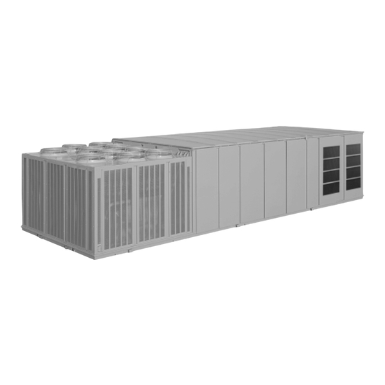
- Page 1 Packaged Rooftop Air Conditioners ™ IntelliPak Rooftops 20 - 130 T ons — 60 Hz 20 - 75 Tons 90 - 130 Tons RT -PRC010-EN March 2003...
-
Page 2: Introduction
Optionally, for centralized building control on-site, or from a remote impressive lineup of features make the location, IntelliPak can be configured for Trane IntelliPak Rooftop line the number direct communication with a Trane one choice for today and the future. -
Page 3: Table Of Contents
Contents Introduction Features and Benefits Application Considerations Selection Procedure Model Number Description General Data Performance Data Performance Adjustment Factors Controls Electric Power Dimension and Weights Mechanical Specifications Options RT-PRC010-EN... -
Page 4: Features And Benefits
20 to 90 ton units forward-curved fans with a 2 line x 40 character English • Trane’s air quality (Traq™) sensor and two inch high efficiency display and a 16 function keypad that • Modulating Gas Heat... - Page 5 • The microprocessor unit controls rooftop operation. and heat based on space coordinates the operation of the • Trane Scroll compressors are used on requirements. rooftop with quality, industry-accepted 20 to 130 ton units. They are designed • Variable Frequency Drives (VFD) components for service ease.
- Page 6 Tracer Trane’s, and Trane’s! Rooftops Building Automation System with a The IntelliPak rooftop, as a part of an • cooling and heating setpoints Trane Control Interface (TCI) or Tracer Integrated Comfort system, provides • zone setpoint offsets for use with with LonTalk®...
-
Page 7: Comfort Control
The And most of the operating hours of the without a bypass option. Bypass control Trane UCM can be set up to operate 100 percent modulating exhaust system will simply provide full nominal airflow under one of three control applications: are at part load, saving more energy. - Page 8 400,000 hours of laboratory testing Research and field operation. This work combined Simple Design with 70% Fewer Parts with over 25 patents makes Trane the With over twenty years of development Fewer parts than an equal capacity worldwide leader in air conditioning...
-
Page 9: Application Considerations
Human Interface Panel. pressure. The Trane 100 percent IntelliPak™ Rooftop units offer four types Advantages of the Statitrac™ modulating exhaust system with of exhaust systems: 100 percent modulating exhaust... - Page 10 The experience of The Trane in the unit return section also increases, exhaust air dampers, resulting in less Company is that a non-modulating opening the dampers and relieving air.
- Page 11 The first Figure AC-1 is a simplified sketch of the heat) and SLHF (hot water heat) rooftops applies to all IntelliPak™ Rooftop units. rooftop showing which panels can be can be field modified to supply and Special field supplied curbs are installed used for horizontal supply and/or return.
- Page 12 If exhaust fans are being horizontal supply and/or return. On 90 to much the same way as on S*HFs by used on an IntelliPak Rooftop unit with 130 ton units, only one side of the removing the exhaust fan access door...
- Page 13 50°F can cause ventilation override sequences on both extended period depending on the hours condensation to form on the heat CV and VAV IntelliPak Rooftops. For your exchanger, leading to premature failure. RT-PRC010-EN...
- Page 14 When two or more units are to be placed sound levels are acceptable. Trane’s IntelliPak Rooftops 20 to 130 tons. side by side, the distance between the Ask your local Trane representative for units should be increased to 150 percent Several basic guidelines for unit this informative engineering bulletin.
- Page 15 Application Considerations Duct Design Figure AC-4 — Unit Placement It is important to note that the rated capacities of the rooftop can be met only if the rooftop is properly installed in the field. A well-designed duct system is essential in meeting these capacities. The satisfactory distribution of air throughout the system requires that there be an unrestricted and uniform...
-
Page 16: Selection Procedure
2.76 inches, enter Table Trane single-zone air conditioner. The 80 DB/65 WB, 95 F outdoor air PD-36. Table PD-36 shows 15.3 bhp with sample selection is based on the temperature and 17 ,500 total supply cfm 924 rpm. - Page 17 Selection Procedure HEATING CAPACITY SELECTION Chart SP-1 — Fan Motor Heat Step 1 — Determine Air Temperature STANDARD MOTOR Entering Heating Module HIGH EFFICIENCY MOTOR Mixed air temperature = RADB + % OA (OADB - RADB) = 70 + (0.10) (0 - 70) = 63 Supply air fan motor heat temperature rise = 46,000 Btu ÷...
- Page 18 First, determine the air density ratio drop. using Figure PAF-1. Return duct static pressure = 0.65 inches Trane roof curb (Table PD-43) = 0.12 Divide the static pressure at the inches nonstandard condition by the air Total return system negative static density ratio to obtain the corrected pressure = 0.77 inches...
- Page 19 Selection Procedure In order to better illustrate this HEATING CAPACITY SELECTION procedure, the following example is Step 1 — Determine Air Temperature used: Entering Heating Module Consider a 60 ton rooftop unit that is to Mixed air temperature = RADB + % OA deliver 18,000 actual cfm at 3-inches total (OADB - RADB) = 70 + (0.10) (0 - 70) = 63 static pressure (tsp), 55 F leaving air...
-
Page 20: Model Number Description
D = 1.25”, E = 1.5”, F = 2”. w/o Inlet Guide Vanes tion Bridge 3 = VAV Supply Air Temperature Control = Trane Communication DIGIT 10 — DESIGN SEQUENCE w/ Inlet Guide Vanes Interface (TCI) Module A = First (Factory Assigned) - Page 21 U.L. agency approval. The service digit for each model number contains 38 digits; all 38 digits must be referenced. = Trane LonTalk Communication 2. EXAMPLE: Model numbers: SXHGD1140AH7CF8D3001 describes a unit with the following characteristics: DX cooling with...
-
Page 22: General Data
General Data Table GD-1— General Data — 20-40 Tons 20 Ton 25 Ton 30 Ton 40 Ton Compressor Data Number/Size (Nominal) 2/10 Ton 1/10 Ton, 1/15 Ton 2/15 Ton 4/10 Ton Model Scroll Scroll Scroll Scroll Unit Capacity Steps (%) 100/50 100/40 100/50... - Page 23 General Data Table GD-1— General Data — 20-40 Tons Continued 20 Ton 25 Ton 30 Ton 40 Ton Filters Panel Filters Number/Size (Inches) 12 — 20x20x2 12 — 20x20x2 16 — 20x20x2 16 — 20x25x2 Face Area (Ft) 33.3 33.3 44.4 55.5 Bag Filters...
- Page 24 General Data Table GD-2 — General Data — 50-75 Tons 50 Ton 55 Ton 60 Ton 70 Ton 75 Ton Compressor Data Standard High Capacity Number/Size (Nominal) 2/10, 2/15 Ton 4/15 Ton 4/15 Ton 4/10, 2/15 Ton 4/10, 2/15 Ton 4/10, 2/15 Ton Model Scroll...
- Page 25 General Data Table GD-2 — General Data — 50-75 Tons Continued 50 Ton 55 Ton 60 Ton 70 Ton 75 Ton Filters Panel Filters Number/Size (Inches) 20 — 20x25x2 20 — 20x25x2 35 — 16x20x2 35 — 16x20x2 35 — 16x20x2 Face Area (Ft) 69.4 69.4...
- Page 26 General Data Table GD-3 — General Data — 90-130 Tons 90 Ton 105 Ton 115 Ton 130 Ton Compressor Data Number/Size (Nominal) 2/10, 4/15 Ton 6/15 Ton 4/10, 4/15 Ton 8/15 Ton Model Scroll Scroll Scroll Scroll Unit Capacity Steps (%) 100/69/38/19 100/67/33/17 100/70/40/20...
-
Page 27: Multiplier
Notes: 1. This information is rated and tested in accordance with ARI Standard 360-93 for large unitary equipment up to 25 tons. These Trane products can be Table GD-6 — Economizer Outdoor Air Damper Leakage (Of Rated Airflow) found in the current ARI Directory. - Page 28 Performance Adjustment Factors Table PAF-1 — Enthalpy of Saturated AIR Figure PAF-1 — Air Density Ratios Altitude/Temperature Correction Wet Bulb Temperature Btu Per Lb. 15.23 15.70 16.17 16.66 17 .15 17.65 18.16 18.68 19.21 19.75 20.30 20.86 21.44 Air Density 22.02 Ratio (Density at New...
- Page 29 (20 Ton) Performance Data Table PD-1 — 20 Ton Gross Cooling Capacities (MBh) — STANDARD CAPACITY Evaporator Coil With Scroll Compressor Ambient Temperature Entering Wet Bulb (F) CAP SHC CAP SHC CAP SHC CAP SHC CAP SHC CAP SHC CAP SHC CAP SHC CAP SHC CAP SHC CAP SHC CAP SHC 194 140 215 187 136 208 112...
- Page 30 (25 Ton) Performance Data Table PD-3 — 25 Ton Gross Cooling Capacity — STANDARD CAPACITY Evaporator Coil With Scroll Compressor Ambient Temperature Entering Wet Bulb (F) CAP SHC CAP SHC CAP SHC CAP SHC CAP SHC CAP SHC CAP SHC CAP SHC CAP SHC CAP SHC CAP SHC CAP SHC 245 179 272 148 301 237 175 263 143 290 107...
- Page 31 Performance (30 Ton) Data Table PD-5 — 30 Ton Gross Cooling Capacity — STANDARD CAPACITY Evaporator Coil With Scroll Compressor Ambient Temperature Entering Wet Bulb (F) CAP SHC CAP SHC CAP SHC CAP SHC CAP SHC CAP SHC CAP SHC CAP SHC CAP SHC CAP SHC CAP SHC CAP SHC 312 230 346 188 382 142 301 224 333 182 368 137...
- Page 32 (40 Ton) Performance Data Table PD-7 — 40 Ton Gross Cooling Capacity — STANDARD CAPACITY Evaporator Coil With Scroll Compressor Ambient Temperature Entering Wet Bulb (F) CAP SHC CAP SHC CAP SHC CAP SHC CAP SHC CAP SHC CAP SHC CAP SHC CAP SHC CAP SHC CAP SHC CAP SHC 395 289 438 237 483 179 382 282 423 230 467 173...
- Page 33 Performance (50 Ton) Data Table PD-9 — 50 Ton Gross Cooling Capacity — STANDARD CAPACITY Evaporator Coil With Scroll Compressor Ambient Temperature Entering Wet Bulb (F) CAP SHC CAP SHC CAP SHC CAP SHC CAP SHC CAP SHC CAP SHC CAP SHC CAP SHC CAP SHC CAP SHC CAP SHC 521 382 578 313 638 238 502 372 557 304 615 229...
- Page 34 Performance (55 Ton) Data Table PD-11 — 55 Ton Gross Cooling Capacity — STANDARD CAPACITY Evaporator Coil With Scroll Compressor Ambient Temperature Entering Wet Bulb (F) CAP SHC CAP SHC CAP SHC CAP SHC CAP SHC CAP SHC CAP SHC CAP SHC CAP SHC CAP SHC CAP SHC CAP SHC 637 470 706 384 782 291 614 457 681 372 753 279...
- Page 35 Performance (60 Ton) Data Table PD-13 — 60 Ton Gross Cooling Capacity — STANDARD CAPACITY Evaporator Coil With Scroll Compressor Ambient Temperature Entering Wet Bulb (F) CAP SHC CAP SHC CAP SHC CAP SHC CAP SHC CAP SHC CAP SHC CAP SHC CAP SHC CAP SHC CAP SHC CAP SHC 617 467 683 379 754 279 596 456 659 367 726 268...
- Page 36 Performance (70 Ton) Data Table PD-15 — 70 Ton Gross Cooling Capacity — STANDARD CAPACITY Evaporator Coil Ambient Temperature (F) AIR- Entering Wet Bulb (F) FLOW (F) CAP SHC CAP SHC CAP SHC CAP SHC CAP SHC CAP SHC CAP SHC CAP SHC CAP SHC CAP SHC CAP SHC CAP SHC 742 558 824 449 913 327 708 538 786 430 872 308...
- Page 37 Performance (75 Ton) Data Table PD-16 — 75 Ton Gross Cooling Capacity — STANDARD CAPACITY Evaporator Coil Ambient Temperature (F) AIR- Entering Wet Bulb (F) FLOW (F) CAP SHC CAP SHC CAP SHC CAP SHC CAP SHC CAP SHC CAP SHC CAP SHC CAP SHC CAP SHC CAP SHC CAP SHC 767 576 853 462 946 340 731 555 814 441 903 320...
- Page 38 Performance (90 Ton) Data Table PD-18 — 90 Ton Gross Cooling Capacity — STANDARD CAPACITY Evaporator Coil Ambient Temperature AIR- Entering Wet Bulb FLOW (F) CAP SHC CAP SHC CAP SHC CAP SHC CAP SHC CAP SHC CAP SHC CAP SHC CAP SHC CAP SHC CAP SHC CAP SHC 929 749 1029 583 1137 408 885 723 981 559 1084 385...
- Page 39 Performance (105 Ton) Data Table PD-20 — 105 Ton Gross Cooling Capacity — STANDARD CAPACITY Evaporator Coil Ambient Temperature AIR- Entering Wet Bulb FLOW (F) CAP SHC CAP SHC CAP SHC CAP SHC CAP SHC CAP SHC CAP SHC CAP SHC CAP SHC CAP SHC CAP SHC CAP SHC 75 1085 885 1198 689 1320 477 1035 857 1143 660 1260 452...
- Page 40 Performance (115, 130 Tons) Data Table PD-22 — 115 Ton Gross Cooling Capacity With 5-Row I-F Evaporator Coil — 100% Load Ambient Temperature AIR- Entering Wet Bulb FLOW (F) CAP SHC CAP SHC CAP SHC CAP SHC CAP SHC CAP SHC CAP SHC CAP SHC CAP SHC CAP SHC CAP SHC CAP SHC 75 1234 993 1361 776 1496 539...
- Page 41 Performance Data Table PD-24 — Natural Gas Heating Capacities Heat Heat Air Temperature Rise Vs Unit Cfm Nom. Heat Input Output Tons Module (MBh) (MBh) 4000 5000 5760 6000 6284 7000 8000 9000 9792 10000 10682 10830 11200 11750 12000 13500 15000 16129 18000 20000 22500 23040 25000 27000 29377 30000 192.7 High 410.0...
-
Page 42: Controls
Performance Data Table PD-28 — 20 to 75-Tons Electric Heat Air Temperature Rise Total Input 4000 6000 8000 10000 12000 14000 16000 18000 20000 22000 24000 26000 102.4 23.6 15.7 11.8 7 .9 170.6 39.3 26.2 19.7 15.7 13.1 11.2 7 .9 7 .1 238.8... - Page 43 1. Capacities expressed as MBh per initial temperature difference (ITD) between the entering air temperature to the hot water coil and the entering water temperature. Ethylene glycol or other capacities can be determined from the Trane heating coil computer program. Capacity and pressure drop of ethylene glycol varies greatly with temperature and concentration.
- Page 44 18.22 Notes: 1. Fan performance for 20 and 25 ton rooftops is identical. However, note maximum motor hp size for each size. Contact your local Trane representative for information on oversized motors. 2. Shaded areas at table extremes note non-standard Bhp or Rpm selection. Contact your local Trane representative for more information.
- Page 45 Performance (20, 25 Tons) Data Figure PD-1— Supply Fan Performance With VARIABLE FREQUENCY DRIVE or WITHOUT INLET VANES — 20 and 25 Tons S_HFC20 & 25 Ton 1700 RPM Dual 15 X 15 Fans Entrance Losses 1600 RPM - w ithout Inlet Guide Vanes - w ithout Evap Coil 20 HP - w ithout Filters...
- Page 46 18.76 Notes: 1. Fan performance for 20 and 25 ton rooftops is identical. However, note maximum motor hp size for each size. Contact your local Trane representative for information on oversized motors. 2. Shaded areas at table extremes note non-standard Bhp or Rpm selection. Contact your local Trane representative for more information.
- Page 47 (20, 25 Tons) Performance Data Figure PD-2 — Supply Fan Performance WITH INLET VANES — 20 and 25 Tons S_HFC20 & 25 Ton 1700 RPM Entrance Losses - w ith Inlet Guide Vanes 1600 RPM - w ithout Evap Coil - w ithout Filterts - w ithout Return Air dampers 20 HP...
- Page 48 Notes: 1. Shaded areas at table extremes note non-standard Bhp or Rpm selection. Contact your local Trane representative for more information. 2. Supply fan performance table includes internal resistance of rooftop. For total static pressure determination, system external static must be added to appropriate component static pressure drops (evaporator coil, filters, optional economizer, optional exhaust fan, optional heating system, optional cooling only extended casing, optional roof curb).
- Page 49 Performance (30 Ton) Data Figure PD-3— Supply Fan Performance With VARIABLE FREQUENCY DRIVE or WITHOUT INLET VANES — 30 Ton S_HFC30 Dual 18 X 18 Fans Entranc e Losses 1400 RPM - w ithout Inlet Guide V anes - w ithout Ev ap Coil - w ithout Filters 1300 RPM - w ithout Return A ir Dampers...
- Page 50 Notes: 1. Shaded areas at table extremes note non-standard Bhp or Rpm selection. Contact your local Trane representative for more information. 2. Supply fan performance table includes internal resistance of rooftop. For total static pressure determination, system external static must be added to appropriate component static pressure drops (evaporator coil, filters, optional economizer, optional exhaust fan, optional heating system, optional cooling only extended casing, optional roof curb).
- Page 51 Performance (30 Ton) Data Figure PD-4 — Supply Fan Performance WITH INLET VANES — 30 Ton S_HFC30 Dual 18 X 18 Fans Entrance Losses 1400 RPM - w ith Inlet Guide Vanes - w ithout Evap Coil - w ithout Filters 25 HP 1300 RPM - w ithout Return Air Dampers...
- Page 52 1. Fan performance for 40, 50, and 55 ton rooftops is identical. However, note maximum motor hp size for 4.250 4.500 4.750 5.000 each size. Contact your local Trane representative for information on oversized motors. 8000 1081 14.75 1108 15.78 1134 16.83...
- Page 53 Performance (40, 50, 55 Tons) Data Figure PD-5 — Supply Fan Performance With VARIABLE FREQUENCY DRIVE or WITHOUT INLET VANES — 40, 50 and 55 Tons SQHFC40, C50, C55 Dual 20 X 20 Fans Entrance Losses 1200 RPM - w ithout Inlet Guide Vanes - w ithout Evap Coil 40 HP - w ithout Filters...
- Page 54 Total Static Pressure 1. Fan performance for 40, 50, and 55 ton rooftops is 4.250 4.500 4.750 5.000 identical. However, note maximum motor hp size for each size. Contact your local Trane representative for 8000 1087 14.97 1114 16.01 1141 17.07...
- Page 55 Performance (40, 50, 55 Tons) Data Figure PD-6 — Supply Fan Performance WITH INLET VANES — 40, 50 and 55 Ton S_HFC40, C50, C55 Dual 20 X 20 Fans Entrance Losses - w ith Inlet Guide Vanes 1200 RPM - w ithout Evap Coil 40 HP - w ithout Filters 30 HP...
- Page 56 43.85 Notes: 1. Fan performance for 60, 70 and 75 ton rooftops are identical. However, note maximum motor hp size for each size. Contact your local Trane representative for information on non-standard motors. 2. Shaded areas at table extremes note non-standard Bhp or Rpm selection. Contact your local Trane representative for more information.
- Page 57 Performance (60, 70, 75 Tons) Data Figure PD-7 — Supply Fan Performance With VARIABLE FREQUENCY DRIVE or WITHOUT INLET VANES — 60, 70 and 75 Tons 1200 RPM S_HFC60, C70, C75 Dual 22 X 22 Fans 1100 RPM Entrance Losses - w ithout Inlet Guide Vanes 50 HP - w ithout Evap Coil...
- Page 58 Notes: 1. Fan performance for 60, 70 and 75 ton rooftops are identical. Contact your local Trane representative for information on non-standard motors. 2. Shaded areas at table extremes note non-standard Bhp or Rpm selection. Contact your local Trane representative for more information.
- Page 59 Performance (60, 70, 75 Tons) Data Figure PD-8 — Supply Fan Performance WITH INLET VANES — 60, 70 and 75 Tons 1200 RPM S_HFC60, C70, C75 Dual 22 X 22 Fans 1100 RPM Entrance Losses - w ith Inlet Guide Vane 50 HP - w ithout Evap Coil - w ithout Filters...
- Page 60 Performance (90 Ton) Data Table PD-40 — Supply Fan Performance WITH VARIABLE FREQUENCY DRIVE or WITHOUT INLET GUIDE VANES — 90 Ton Total Static Pressure Std. 0.250 0.500 0.750 1.000 1.250 1.500 1.750 2.000 27000 4.62 6.01 7.13 8.31 9.53 10.71 11.97 13.34...
- Page 61 Notes: 1. Shaded areas indicate non-standard BHP or RPM selections. Contact your local Trane representive for more information. 2. Supply fan performance table includes internal resistance of rooftop. For total static pressure determination, system external static must be added to appropriate component static pressure drops, (evaporator coil, filters, optional economizer, optional heating system, optional roof curb).
- Page 62 Performance (90 Ton) Data Table PD-41 — Supply Fan Performance WITH INLET GUIDE VANES — 90 Ton Total Static Pressure Std. 0.250 0.500 0.750 1.000 1.250 1.500 1.750 2.000 27000 6.14 7.25 8.39 9.55 10.81 12.11 13.44 14.77 28000 6.76 7.92 9.07 10.28...
- Page 63 Notes: 1. Shaded areas indicate non-standard BHP or RPM selections. Contact your local Trane representive for more information. 2. Supply fan performance table includes internal resistance of rooftop. For total static pressure determination, system external static must be added to appropriate component static pressure drops, (evaporator coil, filters, optional economizer, optional heating system, optional roof curb).
- Page 64 Performance (105,115,130 Tons) Data Table PD-42 — Supply Fan Performance WITH VARIABLE FREQUENCY DRIVE or WITHOUT INLET GUIDE VANES — 105, 115, 130 Ton Total Static Pressure Std. 0.250 0.500 0.750 1.000 1.250 1.500 1.750 2.000 31000 6.40 8.14 9.60 10.84 12.17 13.61...
- Page 65 Notes: 1. Shaded areas indicate non-standard BHP or RPM selections. Contact your local Trane representive for more information. 2. Supply fan performance table includes internal resistance of rooftop. For total static pressure determination, system external static must be added to appropriate component static pressure drops, (evaporator coil, filters, optional economizer, optional heating system, optional roof curb).
- Page 66 Performance (105,115,130 Tons) Data Table PD-43— Supply Fan Performance WITH INLET GUIDE VANES — 105,115,130 Tons Total Static Pressure Std. 0.250 0.500 0.750 1.000 1.250 1.500 1.750 2.000 31000 8.88 10.17 11.44 12.74 14.08 15.51 16.99 1004 18.47 32000 9.68 11.01 12.32 13.66...
- Page 67 Notes: 1. Shaded areas indicate non-standard BHP or RPM selections. Contact your local Trane representive for more information. 2. Supply fan performance table includes internal resistance of rooftop. For total static pressure determination, system external static must be added to appropriate component static pressure drops, (evaporator coil, filters, optional economizer, optional heating system, optional roof curb).
- Page 68 Performance (20 -75 Tons) Data Table PD-44 — Component Static Pressure Drops (in. W.G.) Evaporator Coil Heating System Filters Economizer Throwaway Perm Cartridge With or Nominal Standard High Capacity SFHF/G SEHF/G SLHF/G SSHF/G Std. High Wire Roof Without Tons High All KW’s High High Fiber Effic.
- Page 69 Performance (90-130 Tons) Data Table PD-45 — Component Static Pressure Drops (in. W.G.) Evaporator Coil Heating System Filters Economizer Throwaway Perm Cartridge With or Nominal Standard High Capacity SFHF/G SEHF/G SLHF/G SSHF/G Std. High Wire Roof Without Tons High All KW’s High High Fiber Effic.
- Page 70 Performance Data Table PD-46 — 20-75 — Tons Supply Air Fan Drive Selections 3 Hp 5 Hp 7½ Hp 10 Hp 15 Hp 20 Hp 25 Hp 30 Hp 40 Hp Nominal Drive Drive Drive Drive Drive Drive Drive Drive Drive Tons 1100...
- Page 71 Performance Data Table PD-48 — 20-75 Tons — Modulating 100% Exhaust Fan Performance Negative Static Pressure Nominal 0.250 0.500 0.750 1.000 1.250 1.500 1.750 2.000 Tons 4000 0.38 0.75 1.08 1.45 1.87 2.34 2.88 6000 0.74 1.17 1.65 2.22 2.78 8000 1.59 1.81...
- Page 72 Performance Data Table PD-50 — 20-75 Tons — 100% Exhaust Fan Drive Selections Nominal 3 Hp 5 Hp 10 Hp 15 Hp 20 Hp Tons Drive No Drive No Drive No Drive No Drive No Drive No Drive No 1000 1000 1000 1100...
- Page 73 Performance Data Table PD-52 — 20-75 Tons — 50% Exhaust Fan Performance Negative Static Pressure (In. W.G.) Nominal 0.200 0.400 0.600 0.800 1.000 1.200 1.400 Tons 2000 0.17 0.30 0.45 0.58 0.73 0.90 1.08 20/25 3000 0.36 0.51 0.67 0.88 1.11 1.34 1.54...
- Page 74 Performance Data Table PD-54— 50% Exhaust Fan Drive Selections Nominal 1½ HP 3 HP 5 HP 7½ HP 15 HP Unit Size Drive No Drive No Drive No Drive No Drive No 1000 50/55 70/75 105/115/130 RT -PRC010-EN...
- Page 75 Controls (VAV Units) VAV Units Only Inlet guide vane assemblies installed on the supply fan inlets regulate fan Supply Air Temperature Controls Sequence Of Operation capacity and limit horsepower at lower Cooling/Economizer NOTE: When noted in this sequence system air requirements. When in any “Human Interface Panel,”...
- Page 76 Controls (VAV Units) Heating: Hot Water or Steam Supply Air Setpoint Reset temperature deadband low end, the heating valve is modulated open to On units with hot water or steam Supply air reset can be used to adjust maintain the set minimum supply air heating, the supply air temperature can the supply air temperature setpoint on temperature.
- Page 77 Controls (CV Units) CV Units Only Heating Sequence Of Operation Gas Heating - Two-Stage Upon a call for heating, the UCM closes Occupied Zone Temperature Control the first stage heating contacts Cooling/Economizer beginning the firing sequence. First, the During Occupied cooling mode, the heat exchanger combustion blower economizer (if provided) and mechanical begins operation.
- Page 78 (CV Units) Controls Gas Heating: Modulating Gas drive it full open. If the supply fan is on, or if the outside air damper is open Upon a call for heating, the UCM closes when this freezing condition is sensed, the heating contacts, beginning the firing the supply fan is turned off and the sequence.
- Page 79 Controls (VAV/CV Units) Control Sequences of reached or for 60 minutes, then the unit PRESSURIZE sequence “B” switches to Occupied mode. Operation Common to Both Perhaps a positively pressurized space is VAV and CV Units Note: When using the Morning Warmup desired instead of a negatively option in a VAV heating/cooling rooftop, pressurized space.
- Page 80 LCI-I (LonTalk Communication Interface - Supply Fan - Off Possibly this sequence could be used for for IntelliPak) module installed - Inlet Vanes - Closed (if equipped) purging the air out of a building before - Exhaust Fan - Off (if equipped)
- Page 81 TXV bulb location to shut the through the unit and satisfactory the Trane’s Tracer™ system. A field cooling off when coil frosting conditions temperature control of the building. provided potentiometer or a 0-5 vdc occur.
- Page 82 Trane Tracer™ System and return air enthalpy by measurement of outdoor air and return air The Trane Tracer System can control the temperatures and humidities. Occupied/Unoccupied status of the rooftop. Reference Enthalpy Control of...
-
Page 83: Electrical Data
Electrical Data Electrical Service Sizing then reselect the RDE value to equal the Select a fuse rating equal to the RDE MOP value. value. If the RDE value does not equal a To correctly size electrical service standard fuse size as listed in NEC 240-6, Set 2. - Page 84 Electrical Data Table ED-1 — 20-130 Tons Electrical Service Sizing Data — Compressor Compressor Nominal Voltage Number Standard High Nominal Capacity Capacity Tons Coil Type Unit KW (ea) KW (ea) (ea) (ea) (ea) (ea) (ea) (ea) (ea) (ea) Compressor Std and Hi-Cap 10.2 41.9 41.9...
- Page 85 Electrical Data Table ED-2— 20-130 Tons Electrical Service Sizing Data — Motors Table ED-4 — 20-130 Tons Electrical Service Sizing Data — Nominal Voltage Control Power Transformer — Heating and Cooling Modes Digit 2 Voltage Nominal Tons Unit Function Nominal Tons Condenser Fan Motors 20,25,30 A,E,L,S,X...
-
Page 86: Dimensional Data
Dimensional (20 - 75 Tons) Data Figure DD-1 — 20-75 Ton Cooling Only Unit Dimensions — SAHF Table DD-1 — Cooling Only Unit Dimensions (Ft. In.) — SAHF Nominal Tons 20 & 25 21-9 14-0 12-6 0-11 21-9 14-0 12-6 0-11 27-0 1-10... - Page 87 (20 - 75 Tons) Dimensional Data Figure DD-1 — 20-75 Ton Cooling Only Unit Dimensions — SAHF Continued DETAIL “A” COVERS 20, 25, 30, 50 AND 55 TON UNITS DETAIL “B” COVERS 40, 60, 70 AND 75 TON UNITS RT-PRC010-EN...
- Page 88 Dimensional (20 - 75 Tons) Data Figure DD-2 — 20-75 Ton Heating/Cooling Unit Dimensions Page 87 Table DD-2 — Heating/Cooling Unit Dimensions (Ft. In.) — SEHF , SFHF , SSHF, SLHF , SXHF Nom. Tons 16-9¾ 16-6 16-3 20 & 25 24-1 16-7 15-5...
- Page 89 Dimensional (20 - 75 Tons) Data Figure DD-3 — 20 - 75 Ton Optional Roof Curb Dimensions (Downflow) Note: The pedestal was purposely designed ” shorter than the curb because the unit’s base rails rest on the pedestal at one point and on the curb at a different point.
- Page 90 Dimensional (90 - 130 Tons) Data Figure DD-4 — 90, 105, 115, 130 Ton Heating/Cooling and Cooling Only Rooftops Figure DD-5 — 90 - 130 Tons — Service Clearance Notes: 1. Provide unrestricted clearance over the condenser fans. 2. A minimum clearance of 2’ 4-1/2” is required to open the hinged SEE NOTE 5 control panel doors.
- Page 91 Dimensional (90 - 130 Tons) Data Figure DD-6 — 90 - 130 Ton Roof Curb Dimensions Note: The pedestal was purposely designed ” shorter than the curb because the unit’s base rails rest on the pedestal at one point and on the curb at a different point. Cross Section Thru Roof Curb and base pan SECTION B-B...
-
Page 92: Variable Air Volume Vav
Dimensional (Variable Air Data Volume VAV) Field Installed Sensors SINGLE SETPOINT SENSOR WITH SYSTEM FUNCTION LIGHTS (BAYSENS021*) PROGRAMMABLE NIGHT -SETBACK SENSOR (BAYSENS020*) Note: 1. Remote sensors are available for use with all zone sensors to provide remote sensing capabilities. RT -PRC010-EN... -
Page 93: Constant Volume Cv
Dimensional (Constant Data Volume CV) Field Installed Sensors PROGRAMMABLE NIGHT-SETBACK SENSOR (BAYSENS019*) DUAL SETPOINT, MANUAL/AUTOMATIC CHANGEOVER SENSOR WITH SYSTEM FUNCTION LIGHTS (BAYSENS010*) WITHOUT LED STATUS INDICATORS (BAYSENS008*) SINGLE SETPOINT WITHOUT LED STATUS INDICATORS (BAYSENS006*) Note: 1. Remote sensors are available for use with all zone sensors to provide remote sensing capabilities. RT-PRC010-EN... - Page 94 Dimensional (CV and VAV) Data Integrated Comfort™ System Sensors ZONE TEMPERATURE SENSOR W/TIMED OVERRIDE BUTTONS ZONE TEMPERATURE SENSOR W/TIMED OVERRIDE BUTTON (BAYSENS013*) ALSO AVAILABLE SENSOR ONLY (BAYSENS017*) AND LOCAL SETPOINT ADJUSTMENT (BAYSENS014) REMOTE MINIMUM POSITION POTENTIOMETER CONTROL (BAYSTAT023*) TEMPERATURE SENSOR (BAYSENS016*) Note: 1.
- Page 95 Weights Table W-1 — Approximate Operating Weights (Lbs./Kg) Rooftops Without Exhaust Fans Rooftops With Exhaust Fans Roof Curb Nominal All Heating Tons SL/SS SL/SS Units & SXHF/G 20 Lb. 4000 4220 4330 4620 4330 4360 4580 4690 4970 4690 1814 1914 1964 2096...
- Page 96 Single zone VAV with Johnson S350 controller or terminal strip control TRAQ sensing with ventilation control module Trane Communication Interface Module: ICS interface control module Variable frequency drive (VFD) control of supply/exhaust fan motor Ventilation override module (five ventilation override sequences)
- Page 97 1. Options are provided for informational purposes only. For specifics, contact your local Trane sales office. 2. Special Options may be subject to a net price add. 3. To determine if agency approval is available for special designs, contact your local Trane sales office. RT-PRC010-EN...
- Page 98 Options Table O–1 Comprehensive Listing of Available Options and Accessories Continued Enhanced Standard Factory Design Field Design Facility Installed Standard Special Special Accessory Option or Accessory Manville Tuff-Skin insulation w/ 25/50 flame/smoke development rating Solid double wall Motors 40 hp 200 and 230 volt motors — supply fan High efficiency motors Totally enclosed fan-cooled (TEFC) motors Totally enclosed non-ventilated (TENV) motors –...
- Page 99 1. Options are provided for informational purposes only. For specifics, contact your local Trane sales office. 2. Special Options may be subject to a net price add. 3. For information on agency approval for special designs, contact your local Trane sales office. RT-PRC010-EN...
- Page 100 Options Options position. Barometric dampers at fan • 90-95 Percent Cartridge Filter (with outlet prevent air backdraft. prefilter) — These twelve-inch deep A full range of factory-installed modular • 100 Percent Modulating Exhaust Fan — cartridge filters are mounted in a options are available on standard ship Two double inlet forward-curved fans galvanized steel frame.
- Page 101 Options discharge air microprocessor • VAV Supply Air Temperature Control • Ultra Low Leak Fresh Air Dampers — controller, a discharge air sensor, with Variable Frequency Drives and Dampers have chlorinated polyvinyl pressure sensor and inlet guide vanes. Bypass — Bypass control provides full chloride gasketing to seal to a leakage The microprocessor controller nominal airflow in the event of drive...
- Page 102 (LCI-I) module, which is required for • Trane Communication Interface supply air temperature control. communication with Tracer Summit or Module — provides interface to Trane’s • Zone Sensor — sensor with supply air a 3rd party building automation Integrated Comfort system (ICS), which single temperatures setpoint and system.
-
Page 103: Mechanical Specifications
All units shall be UL approved Trane 3-D Scroll compressor includes and factory run tested. Cooling capacity centrifugal oil pump, oil level sightglass shall be rated in accordance with ARI and oil charging valve. -
Page 104: Options
Mechanical Specifications AIR HANDLING SYSTEM Controls Direct field wiring to the I/O boards is not acceptable. Unit shall be completely factory wired Supply Fan with necessary control and contactor The microprocessor’s memory shall be 20 - 75 Ton Units pressure lugs or terminal block for non-volatile EEPROM type requiring no All supply fans shall have two double- power wiring. - Page 105 Mechanical Specifications Standard filters provided shall be two- 50 percent exhaust air fan option factory before being installed in unit. inch thick throwaway glass fiber filter, Exhaust fan shall be test run as part of One, double inlet, forward-curved fan 30 percent efficient mounted in a metal unit final run test.
- Page 106 Mechanical Specifications Outside Air Ultra low-leak economizer dampers option General Standard low leak dampers shall be Three outside air options: 100 percent provided with chlorinated polyvinyl return air, 0 to 25 percent manually chloride gasketing added to the damper controlled outside air, and 0-100 percent blades and rolled stainless steel jamb fully modulating economizer.
-
Page 107: Heating System
Mechanical Specifications Heating System knocked down for easy assembly. steel secondary heat exchanger Channel shall be provided to allow for surfaces. Free floating design shall Electric heating option adjustment of return air opening eliminate expansion and contraction All electric heat models shall be stresses and noises. - Page 108 Stocking Location Webb/Mason Standard Companies www.trane.com For more information contact your local district office, or e-mail us at Trane has a policy of continuous product and product data improvement and reserves the right to change comfort@trane.com design and specifications without notice.
Need help?
Do you have a question about the IntelliPak and is the answer not in the manual?
Questions and answers