Table of Contents
Advertisement
Advertisement
Table of Contents

Related Manuals for TOHATSU MFS 9.9E


Summary of Contents for TOHATSU MFS 9.9E
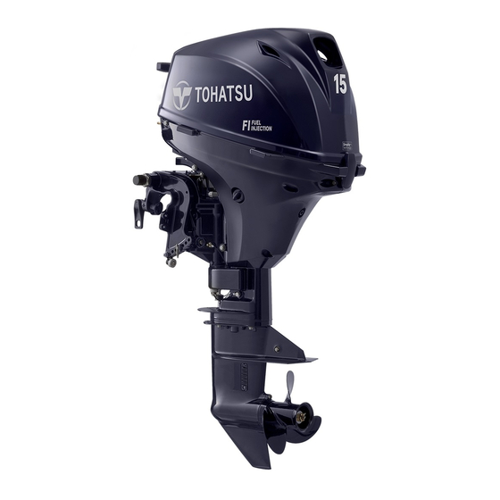
- Page 1 O W N E R’ S M A N U A L AAAA MFS 9.9E MFS 15E MFS 20E OB No.003-11143-7BB1...
- Page 2 MANUAL IN A SAFE LOCATION FOR FUTURE REFERENCE. Copyright © 2022 Tohatsu Corporation. All rights reserved. No part of this manual may be reproduced or transmitted in any from or by any means without the express written permission of Tohatsu Corporation.
- Page 3 In case you encounter any problems, please contact an authorized TOHATSU service shop or dealer for assistance. Tohatsu Corporation reserves the right to change, modify, add, or remove a part or whole of the owner’s manual without prior notice and incurring any obligations.
- Page 4 BE COVERED BY THE APPLICABLE LIMITED WARRANTY, IF THIS PROCEDURE IS NOT FOL- LOWED. ENOM00003-1 PRE-DELIVERY INSPECTION Make sure Pre-delivery inspection has been properly done by authorized TOHATSU dealer before operating your outboard motor. ENOM00005-1 Serial Number Your outboard motor has a unique serial number. The serial number is identification of outboard motor and is located on the outboard motor as shown in the figures below.
- Page 5 ENOM00007-0 NOTICE: DANGER/WARNING/CAUTION/Note Before installing, operating or otherwise handling your outboard motor, be sure to thor- oughly read and understand this Owner's Manual and carefully follow all of the instruc- tions. Of particular importance is information preceded by the words “DANGER,” “WARNING,”...
-
Page 7: Table Of Contents
CONTENTS 1. GENERAL SAFETY INFORMATION ........10 2. - Page 8 12. TOOL KIT AND SPARE PARTS ........83 13.
- Page 9 INDEX 1. GENERAL SAFETY INFORMATION 2. SPECIFICATIONS 3. PARTS NAME 4. LABEL LOCATIONS 5. INSTALLATION 6. PRE-OPERATING PREPARATIONS 7. ENGINE OPERATION 8. REMOVING AND CARRYING THE OUTBOARD MOTOR 9. ADJUSTMENT 10. INSPECTION AND MAINTENANCE 11. TROUBLESHOOTING 12. TOOL KIT AND SPARE PARTS 13.
-
Page 10: General Safety Information
GENERAL SAFETY INFORMATION ENOM00009-1 SAFE OPERATION OF BOAT As the operator/driver of a boat, you are responsible for the safety of those aboard and those in other boat around yours, and for following local boating regulations. You should be thoroughly knowledgeable on how to correctly operate the boat, outboard motor, and accessories. - Page 11 Be sure to use genuine parts, genuine lubricants, or recom- mended lubricants. Be aware that the installation and use of parts not approved by Tohatsu Corporation will void warranty and may lead to unsafe operating conditions. ENOM00011-1...
-
Page 12: Specifications
SPECIFICATIONS ENOM00810-A MODEL FEATURE Model F9.9E F15E F20E Type Transom heights Tiller Handle Remote Control Power Tilt Manual Tilt ENOM00811-A MODEL NAME EXAMPLE F 20E EPTL Model Product Starter Steering Horse power Tilt system Shaft length description generation system system P= Remote Con- S= Short 15 in T= Power tilt... - Page 13 (ICOMIA 39/94) dB (A) Hand Vibration Level (ICOMIA 38/94) m/sec2 Remark: Specifications are subject to change without notice. *1 With propeller, with battery cable. *2 With Manual Start Tohatsu outboard is power rated in accordance with ISO8665 (propeller shaft output).
- Page 14 (ICOMIA 39/94) dB (A) Hand Vibration Level — (ICOMIA 38/94) m/sec2 Remark: Specifications are subject to change without notice. *1 With propeller, with battery cable. *2 With Manual Start Tohatsu outboard is power rated in accordance with ISO8665 (propeller shaft output).
-
Page 15: Parts Name
PARTS NAME ENOM00303-0 MF, EF, EP, EFT, EPT ENOF01202-1 Tilt Handle Clamp Bracket Carrying Handle Top Cowl Clamp Screw Power Tilt Switch (EPT type Bottom Cowl Stop Switch only) Cooling Water Check Port Throttle Friction Screw Flushing Connector Cap Oil Drain Bolt Throttle Grip Fuel Filter Drive Shaft Housing... - Page 16 PARTS NAME MF, EF, EP, EFT, EPT Power Tilt Type ENOF01203-A3 Primer Bulb Stop Switch Fuel Tank Cap Cord Assembly Air Vent Screw Engine Stop Switch Cord Fuel Connector Power Tilt Switch Fuel Pick up Elbow *3: Power tilt type only. *4: Power tilt, tiller handle type Fuel Tank only.
-
Page 17: Label Locations
LABEL LOCATIONS ENOM00019-A Warning label locations ENOF01204-A5... - Page 18 LABEL LOCATIONS 1, 2-4. Read owner's manual. Engine stop switch (See page 37, 44). 3WL-72180-0 ENOF00131-B 2-1. Hot surface. When laying down the out board motor, be sure this decal is facing up. 2-2. Hazard caused by rotating parts. 2-3. Electrical shock hazard. 3H6 67572 1 For RC model Engine stop switch warning.
- Page 19 LABEL LOCATIONS Warning regarding fuel tank cap (See Warning tag regarding instructions of page 27). the fuel tank cap (See page 27). ENOF00012-A Warning tag regarding combination of fuel tank and primer bulb ass'y (See ENOF00011-0 page 33). Read owner's manual (See page 27). ENOF00005-J ENOF00005-T...
- Page 20 LABEL LOCATIONS ENOM00019-A ECI (Emission Control Information) label locations 1 EMISSION CONTROL INFORMATION 2 THIS ENGINE CONFORMS TO (MODEL YEAR) CALIFORNIA AND U.S. EPA EMISSION REGULATIONS FOR SPARK IGNITION MARINE ENGINES. ( M ODEL YEAR) 3 THIS EQUIPMENT MEETS U.S. EPA EVAP STANDARDS. 4 REFER TO THE OWNER'S MANUAL FOR MAINTENANCE SPECIFICATIONS AND ADJUSTMENTS.
-
Page 21: Installation
INSTALLATION package or their equivalents in terms of ENOM00024-C size, material, quality and strength. 1. Mounting the outboard motor on boat Mounting outboard motor must be per- formed by trained service person(s) in ENOW00006-1B well-equipped place where lift or hoist WARNING can be used. - Page 22 INSTALLATION even swamping or capsizing. Make sure ENOM00025-0 Position ... Above keel line that there is enough distance between Place the outboard motor in the center bottom cowl and water surface to prevent water from entering the engine. of the boat's transom. Make sure to mount the engine in correct position.
- Page 23 INSTALLATION ENOF00016-2 1. Bolt (8 × 85) 2. Nylon locking nut 3. Washer 4. Clamp screw ENOW00945-0 CAUTION Please inspect whether there is a loosen- ENOF00305-0 ing of the clamp screw or mounting bolts before departure. ENOW00008-2A Loosening may cause a dangerous situa- CAUTION tion, such as loss of control.
-
Page 24: Battery Installation
INSTALLATION ENOM00029-A ENOW00014-0 2. Battery installation CAUTION Make sure that the battery leads do not ENOW00012-1 get stuck between the outboard motor WARNING and boat when turning, etc. The starter motor may fail to operate if Battery electrolyte contains sulfuric acid the leads are incorrectly connected. - Page 25 INSTALLATION 2. Connect the positive lead (+) to the positive terminal (+) of the battery, and then connect the negative lead (—). When disconnecting the battery, always remove the negative lead (—) first. After connecting the positive terminal (+), securely place a cap on it to prevent short circuits.
-
Page 26: Pre-Operating Preparations
When operating an outboard motor with The fuel system components on your gasoline containing ethanol, storing gasoline TOHATSU outboard motor will withstand in the fuel tank for long periods should be up to 10% ethyl alcohol (hereinafter avoided. Storing gasoline for long periods referred to as the "ethanol") content in... -
Page 27: Fuel Filling
PRE-OPERATING PREPARATIONS The static electricity may ignite the gaso- ENOW00018-1 line vapor during refueling. WARNING Stop the engine, and do not start the engine during refueling. Fuel leakage can cause fire or explosion, Do not smoke. potentially leading to severe injury or loss of Be careful not to overfill fuel tank. -
Page 28: Engine Oil Filling
PRE-OPERATING PREPARATIONS 1. Fully open the air vent screw on the ENOW00092-1 fuel tank cap and release internal CAUTION pressure. Do not overfill engine oil, or engine oil could leak and/or engine could be dam- aged. If engine oil level is over upper limit marks of oil level gauge, drain oil to level lower than upper limit. - Page 29 PRE-OPERATING PREPARATIONS ENOW0002A-A CAUTION Use of engine oils that do not meet these requirements will result in reduced engine life, and other engine problems. ENOF01240-0 1. Upper limit (Max.) 2. Lower limit (Min.) Engine oil recommendation Use only high quality 4-stroke outboard motor oil to insure performance and pro- longed engine life.
-
Page 30: Break-In
PRE-OPERATING PREPARATIONS ENOM00033-A 4. Break-In Your new outboard motor and lower unit ENOW00023-1 require break-in for the moving compo- CAUTION nents a ccording to the conditions Operating the outboard motor without described in the following time table. break-in can shorten life. Please refer to ENGINE OPERATION sec- If any abnormality is experienced during the tion (See page 33) to learn how to cor-... -
Page 31: Warning System
PRE-OPERATING PREPARATIONS ENOM00039-D 5. Warning system If outboard motor encounters an abnor- mal condition of fault, the warning buzzer will emit a continuous beep or intermit- tent short beeps and the warning lamp will synchronize with the buzzer and engine speed will be limited (engine will ENOF00851-A not be stopped). - Page 32 PRE-OPERATING PREPARATIONS ENOM00041-B Warning indicators, faults and remedy Warning indicators High Description of faults Remedy Sound Lamp (LED) speed speed One beep On for 5 sec. Normal system test when start up Engine speed exceeds maximum Continuous allowable RPM Continuous Low oil pressure Continuous Water over temperature...
-
Page 33: Engine Operation
ENGINE OPERATION ENOM00042-0 ENOW00027-B Before starting CAUTION Before starting engine for the first time after ENOM00246-0 Oil Level checking reassembling engine or off-season storage, disconne c t stop switch lock and crank Check the engine oil level before each approximately 10 times in order to prime the use. - Page 34 ENGINE OPERATION Do NOT use a primer bulb/hose assembly that does not contain a Fuel Demand Valve or a sealing mechanism as shown below: other- wise fuel spillage may occur when the con- nector is connected to the engine. 2 2 2 ENOF00036-0 ENOF00310-1 Do not connect fuel connector except when...
-
Page 35: Starting The Engine
ENGINE OPERATION ENOM00045-F ENOW00036-1 2. Starting the engine CAUTION Operating outboard motor without cooling ENOW00958-1 water will lead to overheating and damage on WARNING the outboard motor severely. In case the cooling water check port is not discharging Do not remove or install the top cowl water, stop the outboard motor immedi- after the engine has started. - Page 36 ENGINE OPERATION Tiller handle type 3. Set the throttle grip to START posi- tion. 1. Be sure to install the stop switch lock to the stop switch, and attach the stop switch lanyard securely to the operator or to the operator's PFD (Personal Flotation Device.) ENOF01107-1 1.
- Page 37 ENGINE OPERATION (For electrical starter type) 4. Push the starter switch button and release the button when the engine has started. ENOF00869-1 1. Stop switch lock 2. Insert the main switch key. ENOF00315-1 3. Set the control lever in the Neutral position.
- Page 38 ENGINE OPERATION ENOM00042-B Emergency starting ENOW00099-1 WARNING When the emergency starter rope is used for starting engine; Start in gear protection does not work. Make sure that shift is in neutral position. If the gear is in Forward or Reverse, the ENOF00871-1 1.
- Page 39 ENGINE OPERATION ENOF01251-0 ENOF00126-1 6. Tie a loop in the another end of the 3. Remove starter lock cable from recoil emergency starter rope and attach starter by pulling the starter lock socket wrench, Both the loop and the cable. wrench are provided in outboard motor box.
-
Page 40: Warming Up The Engine
ENGINE OPERATION 9. Pull the starter handle slowly until you Remark: The idling speed automatically feel engagement, keep pulling till you increases depending on the engine tem- feel less resistance. Then pull it perature. When the engine reaches nor- quickly. mal operating temperature, it will return to the specified idling speed. -
Page 41: Forward, Reverse, And Acceleration
ENGINE OPERATION ENOM00046-A ENOW00861-1 WARNING 4. Forward, reverse, and acceleration Do not shift at high boat speed, or control may be lost, fall down or causing passen- ENOW00037-1 ger(s) to be thrown overboard. Leading to serious personal injury. WARNING ENOW00867-1 Before shifting into forward or reverse, make sure that boat is properly moored and out- WARNING... - Page 42 ENGINE OPERATION Acceleration ENOW00864-0 Open throttle grip gradually. CAUTION Do not increase engine speed unnecessarily when the shift is in neutral and reverse, or engine damage may occur. ENOM00890-A Tiller handle type ENOW00865-A CAUTION ENOF01109-1 1. Throttle grip Do not force to shift when the throttle grip is not in the fully closed position, otherwise, ENOM0900-0 steering system and/or shifting mechanism...
-
Page 43: Stopping The Engine
ENGINE OPERATION Reverse 1. Quickly pull the control lever to the Reverse (R) position at 32°, where the gear will be connected, while lifting up on the lock button located under the control lever grip. 2. Further rearward motion will open the throttle. - Page 44 ENGINE OPERATION ENOF00881-1 ENOF00314-C1 1. Control lever 1. Stop switch 2. Main switch key 2. Stop switch lock 2. Turn the main switch key to the OFF position. ENOF00871-1 1. ON ENOF00869-A 2. START 1. Stop switch 3. OFF 2. Stop switch lock ENOW00869-1 ENOM00910-1 WARNING...
-
Page 45: Steering
ENGINE OPERATION ENOF00891-0 ENOM00920-0 6. Steering ENOF00893-0 ENOW00870-0 WARNING ENOM00050-0 7. Trim angle Sudden steering may cause passenger(s) to be thrown overboard or falling down. ENOW00043-1 Tiller handle type WARNING Right turn Move the tiller handle to the left Adjust the trim angle when the engine is Left turn stopped. - Page 46 ENGINE OPERATION The trim angle of the outboard motor can be adjusted to suit the transom angle of the hull, and load conditions. Choose an appropriate trim angle that will allow the anti-ventilation plate to run parallel to the water surface during operation. ENOM00052-0 ENOF00053-0 Proper trim angle...
-
Page 47: Tilt Up And Tilt Down
ENGINE OPERATION 3. Tilt up the outboard motor. 1. Trim lock pin 2. Higher 4. Remove the thrust rod as shown pic- 3. Lower ture. 6. Reinstall the trim lock pin securely. 5. Reinstall the thrust rod in the desired 7. - Page 48 ENGINE OPERATION position), lift up the outboard motor to ENON00921-1 Note free it from the reverse lock, then release After use, leave the outboard motor to lower the outboard motor. upright for a minute to drain the water from inside the engine. ENOM00062-1B Manual Tilt type Tilt up...
- Page 49 ENGINE OPERATION ENOM00069-A Power Tilt type Tilt up 1. Operate the Power Tilt switch and tilt the outboard motor up. 2. Lock the tilt with the Tilt stopper after the outboard motor has been tilted Tilt down 1. Release the tilt stopper from the set- up position while slightly tilting up ENOF01217-1 outboard motor.
-
Page 50: Shallow Water Operation
ENGINE OPERATION ENOW00054-1A CAUTION Do not over tilt the outboard motor when driving in shallow water, or air may be sucked through water inlet potentially leading to engine overheating. ENOF00326-0 ENOF01144-A 1. Power 1. Water inlet 2. Manual Manual relief valve specified tightening torque Manual tilt type ·... - Page 51 ENGINE OPERATION 2. Return to normal running position: Put the reverse lock lever in the tilt down position, slightly lift up the out- board motor, and then put it down. ENOF00059-0 1. Reverse lock lever 2. Tilt down position 3. Tilt up position ENOM00069-A Power Tilt type 1.
-
Page 52: Removing And Carrying The Outboard Motor
REMOVING AND CARRYING THE OUTBOARD MOTOR ENOM00070-A 1. Removing the outboard motor ENOW00006-1B WARNING To avoid personal injury or damage of equip- ment , make sure the allowable lifting capac- ity of the hoist is at least twice the weight of the outboard motor. -
Page 53: Trailering
REMOVING AND CARRYING THE OUTBOARD MOTOR Otherwise, engine's exterior may be dam- age d or wa ter may enter th e cylinder through the exhaust port and cause engine problems. ENOF01221-1 ENOM00072-1A 3. Trailering ENOW00072-0 ENOF01219-1 CAUTION Trailering in the tilted position may cause Keep the outboard motor in a vertical damage to the outboard motor, boat, etc. - Page 54 REMOVING AND CARRYING THE OUTBOARD MOTOR intended to support the outboard motor while the boat is docked, beached, etc. When transporting a boat on a trailer with the outboard motor attached, dis- connect the fuel line from the outboard motor beforehand and keep the out- board motor in the vertical or on a tran- som saver bar.
-
Page 55: Adjustment
ADJUSTMENT Friction adjustment of the throttle grip ENOM00073-0 1. Steering friction can be made with the throttle adjustment screw. Tiller handle type ENOW00074-1 WARNING Do not over tighten the steering friction lever, it could result in difficult handling of the outboard motor, resulting in the loss of control causing an accident and could lead ENOF00330-1 to severe injury. - Page 56 ADJUSTMENT Side mount type ENOF00078-2 1. Throttle friction adjustment screw 2. Decrease 3. Increase...
-
Page 57: Inspection And Maintenance
INSPECTION AND MAINTENANCE ENOM00077-1 Care of your outboard motor To keep your outboard motor in the best operating condition, it is very important that you perform daily and periodic maintenance as suggested in the mainte- nance schedules as follows. ENOW00077-1 CAUTION Your personal safety and that of your pas- sengers depends on how well you main-... -
Page 58: Daily Inspection
INSPECTION AND MAINTENANCE ENOM00322-1 1. Daily Inspection Perform the following checks before and ENOW00078-1 after use. WARNING Do not use outboard motor if any abnormal- ity is found during pre-operation check oth- erwise it could result in severe damage to the motor or severe personal injury. - Page 59 INSPECTION AND MAINTENANCE Item Points to Check Remedy • Make sure that steering handle and remote control is Repair Steering Devices functioning normally. • Check if the anode is securely installed. Repair if necessary Other parts • Check the anode for corrosion and deformation. Replace ENOM00081-D Oil level checking...
- Page 60 INSPECTION AND MAINTENANCE When replenishing engine oil, be careful colorless and odorless gas which can be fatal not to allow entry of foreign matters such if inhaled for any length of time. as dust and water into oil chamber. Wipe off engine oil well immediately if ENOW00920-0 spilled and dispose of it in accordance CAUTION...
- Page 61 INSPECTION AND MAINTENANCE 2. Remove the flushing connector cap ENOW00036-1A from the outboard motor, and screw CAUTION in the hose joint. When starting the outboard motor in the 3. Connect a water hose. Turn on the test tank, make sure that: water and adjust the flow.
- Page 62 If you are unable to respond to the cause or the fuse continues to blow, request an authorized Tohatsu dealer for inspection. 1. Stop the engine and disconnect the battery cable from the battery nega- tive (-) terminal.
-
Page 63: Periodic Inspection
INSPECTION AND MAINTENANCE ENOM01106-1 2. Periodic Inspection It is important to inspect and maintain your outboard motor regularly. Make sure to per- form each service at interval specified in the chart below. Maintenance intervals are determined by the number of hours outboard motor has been used or number of months, whichever comes first. - Page 64 INSPECTION AND MAINTENANCE Inspection intervals First 20 Every 50 Every 100 Every 200 Every 400 Description Inspection procedure Remarks hours or 1 hours or 3 hours or 6 hours or 1 hours or 2 month months months year year Throttle cable Check and replace if necessary Throttle link*1 Check and adjustment...
- Page 65 INSPECTION AND MAINTENANCE the correct torque as soon as possible with ENOW00933-0 a torque-wrench. CAUTION 7. Reset the engine in a vertical posi- Engine oil mixed with dust or water will dra- tion. matically shorten the life of the engine. 8.
- Page 66 INSPECTION AND MAINTENANCE 2. Lower limit (Min.) ENOM00092-A Oil filter replacement ENON00920-0 Note ENOW00091-1 Use only recommended engine oil (See CAUTION page 29) You may be injured due to high engine tem- peratures if you fill engine oil just after oper- Oil volume needed for complete oil replacement ation.
- Page 67 INSPECTION AND MAINTENANCE Contact authorized dealer for fuel system services. Services by unqualified person could lead to engine damage. Fuel filters are provided inside the fuel tank and engine. ENOF00094-0 ENOM00094-0 Fuel filter (for engine) 1. Oil filter wrench 1. Check the cup for water and debris. P/N 3AC-99090-0 P/N 3AC99090M (US.
- Page 68 INSPECTION AND MAINTENANCE 3. O-ring 4. Filter 5. Float 6. Cup 7. Indicate of Fuel Flow ENOM00096-A Fuel filter (for fuel tank) Water or dirt in the fuel tank will cause engine performance problems. ENOF01242-1 Check and clean the tank at specified 1.
- Page 69 INSPECTION AND MAINTENANCE ENOM00098-A ENON00033-1 Gear oil replacement Note ENOW00076-1 Use genuine gear oil or the recommended one (API GL-5: SAE #80 to #90). WARNING Required volume: approx. 465 mL (15.7 fl.oz.). Be sure that the outboard motor is secured to transom or service stand, or accidental drop or fall of outboard motor could lead to severe personal injury.
- Page 70 INSPECTION AND MAINTENANCE ENOW00086-1 CAUTION Do not install propeller without thrust holder, or propeller boss could be dam- aged. Do not reuse split pin. After installing split pin, spread bend both end of the pin apart to lock propeller in place.
- Page 71 INSPECTION AND MAINTENANCE ENOM00087-A Spark plugs replacement ENOW00087-1 WARNING Do not reuse spark plug, if the insulation is damaged or sparks can leak through crack, potentially leading to electric shock, explosion and/or fire. Do not touch spark plug(s) immediately after stopping engine as they will be hot ENOF00084-C and could cause severe burns if touched.
- Page 72 INSPECTION AND MAINTENANCE 6. Measure the spark plug gap with a wire t ype fe eler g auge. The g ap should be 0.8-0.9 mm (0.031-0.035 inches). If the gap is out of specifica- tion, replace the spark plug with a new one Use spark plug NGK DCPR-6E.
- Page 73 INSPECTION AND MAINTENANCE ENOM00088-1A Anode replacement A sacrificial anode protects the outboard motor from galvanic corrosion. Anode is located on the gear case, cylinder etc.. When the anode is eroded more than 1/3 of original size, replace it. ENON00029-1 Notes Never grease or paint the anode.
- Page 74 INSPECTION AND MAINTENANCE 1. Oil cap ENOM00089-B Power Tilt oil checking 2. Oil level ENOW00088-0 Recommended oil WARNING Use automatic transmission fluid or equivalent. Be sure that outboard motor is secured to Recommended oil is as shown below. transom or service stand, or accidental ATF Dexron III drop or fall of outboard motor could lead to severe personal injury.
- Page 75 INSPECTION AND MAINTENANCE ENOM00960-0 Grease point Apply waterproof grease to the parts shown below. ENOF01232-1 *1 : Other side.
-
Page 76: Off-Season Storage
INSPECTION AND MAINTENANCE 3. Drain all fuel from the fuel hoses, fuel ENOM00100-A 3. Off-season storage pump, fuel filter (See 67) and vapor separator (See 77), and clean these ENOW00934-0 parts. WARNING Keep in mind that if gasoline is kept in the vapor separator for a long time, Be sure to disconnect fuel connector gum and varnish will be developed,... - Page 77 INSPECTION AND MAINTENANCE 9. Place the outboard motor in the ver- tical position under a dry condition. ENOF01221-1 ENOM00950-0 Adding a fuel stabilizer When adding a fuel stabilizer additive (commercially available), first fill the fuel tank with fresh fuel. If the fuel tank is only partially filled, air in the tank can cause the fuel to deteriorate during storage.
- Page 78 INSPECTION AND MAINTENANCE Fuel and fuel vapors are extremely flamma- ble and can be explosive. If fuel is spilled, wipe it up immediately. Keep the fuel tank well away from sources of ignition, e.g. sparks or open flames Perform all work outdoors or in a well ventilated place.
-
Page 79: Pre-Season Check
INSPECTION AND MAINTENANCE ENOM00102-0 Specific Grav- Terminal Volt- Charge Condi- Battery ity at 20°C age (V) tion ENOW00931-A 1.160 11.1 1/4 charged WARNING 1.210 11.7 1/2 charged 1.250 3/4 charged Place the battery away from any source of 1.280 13.2 Fully charged fire, sparks and open flames such as burners or welding equipment. -
Page 80: Cold Weather Precautions
INSPECTION AND MAINTENANCE the water, immediately take it to your ENOM00107-A 7. Striking underwater object dealer. The following are the emergency mea- sures to be taken for a submerged out- ENOW00935-0 board motor. CAUTION 1. Wash the outboard motor with fresh Striking the sea bottom or an underwater water to remove salt or dirt. -
Page 81: Troubleshooting
TROUBLESHOOTING ENOM01109-0 If you encounter a problem, check the list below to determine the cause and to take the proper action. An authorized dealer will always be happy to provide any assistance and information. * Low speed ESG operates. Possible cause Fuel level is low in the tank. - Page 82 TROUBLESHOOTING Possible cause Valve timing is not correct (Belt is stretched or installed incorrectly). Valve clearance is defective. Valve seat sealing is defective. Piston, piston ring and/or cylinder is worn excessively. Combustion chamber car deposition is too much. Spark plug is loose. (Cooling water is lacking.) Pump is defective or clogged.
- Page 83 TOOL KIT AND SPARE PARTS ENOM00327-0 The followings are a list of the tools and spare parts provided with the motor. Items Quantity Remark Tool bag Pliers Socket wrench 10 × 13 mm Service tools Socket wrench 16 mm Socket wrench handle Screwdrivers Cross-and straight-point Screwdriver handle...
- Page 84 PROPELLER TABLE ENOM00329-0 Use a genuine propeller. A propeller must be selected so that the engine RPM measured at wide open throttle while cruising is within the recommended range. 5400–6100 min (rpm) Propeller Size (Blades × diameter × pitch) Propeller Mark Light boats 3 ×...
- Page 85 EMISSION CONTROL SYSTEM INFORMATION ENOM01000-0 ENOM01003-0 Emission Sources Clean Air Acts of the United States and California, and Environment Canada Carbon monoxide, oxides of nitrogen EPA, California, and Canadian regula- and hydrocarbons are produced in the tions require all manufacturers to pro- course of the combustion process.
- Page 86 ENOM01006-0 Replacement Parts 2011. The emission control system in your Tohatsu out board motor has be en designed, built, and certified to conform with the EPA and California emission reg- ulations. Whenever requesting mainte- nance, use of Tohatsu Genuine parts is highly recommended.
- Page 87 FOR UNITED STATES AND CANADA EQUIPPED FOR UNITED STATES AND MODEL CANADA MODEL The Environmental Protect ion Agency TOHATSU adopts Primer bulb/hose (EPA) required portable fuel tank that use assembly approved by the Environment with outboard engines produced after Protection Agency (EPA).
- Page 88 EMISSION CONTROL SYSTEM INFORMATION label identifies engines that meet the Air ENOM01007-0 Maintenance Resources Board’s Personal Watercraft and Out board marine engine 2001 Follow the maintenance schedule pre- exhaust emission standards. sented on page 63. Keep in mind that this Engines meeting these standards have schedule is based on the assumption that 75% lower emissions than conventional...
- Page 89 EMISSION CONTROL SYSTEM INFORMATION Sterndrive and Inboard marine engine 2003-2008 exhaust emission standards. Engines meeting these standards have 65% lower emissions than One Star-Low Emission engines. ENOF01004-0 ENOM01012-0 Four Stars-Super Ultra Low Emission The four-star label identifies engines that meet the Air Resources Board’s Stern- drive and Inboard marine engine 2009 exhaust emission standards.
- Page 90 O W N E R’ S M A N U A L MFS 9.9E MFS 15E MFS 20E 5-4, Azusawa 3-Chome, Itabashi-Ku Tokyo 174-0051, Japan Tel: +81-3-3966-3117 Fax: +81-3-3966-0090 www.tohatsu.com...
Need help?
Do you have a question about the MFS 9.9E and is the answer not in the manual?
Questions and answers