
Subscribe to Our Youtube Channel
Related Manuals for TOHATSU MFS 9.9D


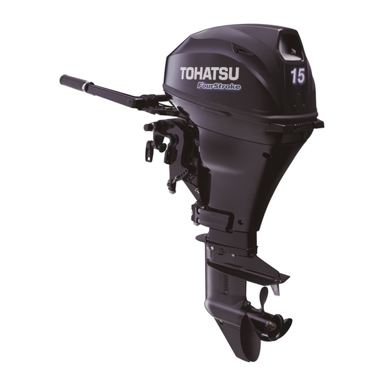
Summary of Contents for TOHATSU MFS 9.9D
- Page 1 OWNER’S MANUAL MFS 9.9D MFS 15D MFS 20D Original instructions OB No.003-11115-3AG1...
- Page 2 INJURY OR DEATH. KEEP THIS MANUAL IN A SAFE LOCATION FOR FUTURE REFERENCE. Copyright © 2017 Tohatsu Corporation. All rights reserved. No part of this manual may be reproduced or transmitted in any from or by any means without the express written permission of Tohatsu Corporation.
- Page 3 ENOM00006-A To You, Our Customer Thank you for selecting a TOHATSU outboard motor. You are now the proud owner of an excellent outboard motor that will service you for many years to come. This manual should be read in its entirety and the inspection and maintenance procedures described later in this manual should be followed carefully.
- Page 4 ENOM00005-A Serial Number In the space below, please record the outboard motor's serial number (indicated both on the swivel bracket and on the cylinder block). The serial number will be needed when ordering parts, and when making technical or warranty inquiries. Serial Number: ENOF01201-0 ENOF01200-1...
- Page 5 ENOM00007-0 NOTICE: DANGER/WARNING/CAUTION/Note Before installing, operating or otherwise handling your outboard motor, be sure to thor- oughly read and understand this Owner's Manual and carefully follow all of the instruc- tions. Of particular importance is information preceded by the words “DANGER,” “WARNING,”...
-
Page 6: Table Of Contents
CONTENTS 1. GENERAL SAFETY INFORMATION ....... 10 2. SPECIFICATIONS ..........12 3. - Page 7 11. TROUBLESHOOTING ......... . 79 12.
- Page 8 INDEX 1 GENERAL SAFETY INFORMATION 2. SPECIFICATIONS 3. PARTS NAME 4. LABEL LOCATIONS 5. INSTALLATION 6. PRE-OPERATING PREPARATIONS 7. ENGINE OPERATION 8. REMOVING AND CARRYING THE OUTBOARD MOTOR 9. ADJUSTMENT 10. INSPECTION AND MAINTENANCE 11. TROUBLESHOOTING 12. ACCESSORIES KIT 13. PROPELLER TABLE...
-
Page 9: General Safety Information
GENERAL SAFETY INFORMATION ENOM00009-0 SAFE OPERATION OF BOAT As the operator/driver of the boat, you are responsible for the safety of those aboard and those in other boat around yours, and for following local boating regulations. You should be thoroughly knowledgeable on how to correctly operate the boat, outboard motor, and accessories. - Page 10 GENERAL SAFETY INFORMATION ENOM00010-0 SERVICING, REPLACEMENT PARTS & LUBRICANTS We recommend that only an authorized service shop perform service or maintenance on this outboard motor. Be sure to use genuine parts, genuine lubricants, or recommended lubricants. ENOM00011-A MAINTENANCE As the owner of this outboard motor, you should be acquainted with correct maintenance procedures following maintenance section of this manual (See page 61).
-
Page 11: Specifications
SPECIFICATIONS ENOM00810-A MODEL FEATURE Model F9.9D F15D F20D Type Transom heights Tiller Handle Remote Control Power Tilt Mnual tilt ENOM00811-A MODEL NAME EXAMPLE F 20D EPTL Model descrip- Horse Product Starter Steering Tilt system Shaft length tion power generation system system P= Remote T= Power... - Page 12 EM (Engine modification) Operator Sound Pressure 83.9 (ICOMIA 39/94) dB (A) Hand Vibration Level (ICOMIA 38/94) m/s Remark: Specifications subject to change without notice. *1 With propeller, with battery cable. Tohatsu outboard is power rated in accordance with ISO8665 (propeller shaft output).
- Page 13 Operator Sound Pressure 83.9 (ICOMIA 39/94) dB (A) Hand Vibration Level — (ICOMIA 38/94) m/s Remark: Specifications subject to change without notice. *1 With propeller, with battery cable. Tohatsu outboard is power rated in accordance with ISO8665 (propeller shaft output).
-
Page 14: Parts Name
PARTS NAME ENOM00303-0 MF, EF, EP, EFT, EPT ENOF01202-0 Tilt Handle Drive Shaft Housing Water Plug Top Cowl Thrust Rod Oil Plug (Upper) (Level) Bottom Cowl Clamp Bracket Oil Plug (Lower) (Fill) Cooling Water Check Port Clamp Screw Oil Filter Power Tilt Switch Throttle Grip Spark Pulg... - Page 15 PARTS NAME MF, EF, EP, EFT, EPT Power Tilt Type ENOF01203-0 Primer Bulb Cord Assembly Fuel Tank Cap Engine Stop Switch Cord Air Vent Screw Power Tilt Switch Fuel Connector *4: Power tilt, tiller handle type only. *5: Remote control type only. Fuel Pick up Elbow Fuel Tank Clamp Screw...
-
Page 16: Label Locations
LABEL LOCATIONS ENOM00019-A Warning label locations 3, 4 ENOF01204-1... - Page 17 LABEL LOCATIONS Warning label urge to read the owner’s Warning label regarding position of manual . outboard motor when setting down. ENOF00120-0 ENOF00006-0 2-1. Warning regarding emergency start- For RC model ing (See page 36). Warning label regarding stop switch 2-2.
- Page 18 LABEL LOCATIONS ENOM00019-B CE label locations r o t 0123 l a i CAN ICES-2/NMB-2 ENOF01237-2 1. Model code(Model name) 2. Rated power 3. Dry mass weight( Without propeller, with battery cable) 4. Serial No. 5. Manufacture name 6. Manufacture address Description of serial number year code Last two digits of alphabet represent production year as below.
-
Page 19: Installation
INSTALLATION Do not operate the outboard motor until it ENOM00024-A has been securely mounted on the boat in 1. Mounting the outboard motor on accordance with the instructions below. boat ENOW00009-0 ENOW00006-B WARNING WARNING Mounting the outboard motor without Before installing the outboard motor on the following this manual can lead to unsafe boat, hang the outboard motor with the conditions such as poor maneuverabil-... - Page 20 INSTALLATION Incorrect outboard motor mounting ENOM00025-0 Position ... Above keel line height or existence of underwater Set engine at center of boat. object(s), such as hull bottom design, bottom surface conditions or underwa- ter accessories, can cause water spray possibly reaching the engine through an opening of the bottom cowling during cruising.
-
Page 21: Remote Control Device Installation
INSTALLATION PTT type transom. Mounting bolts installed with the threaded end at the inside surface of 1. To attach the outboard motor to the the transom can cause personal injury. boat, use the bolts to secure the out- Tighten the bolts sufficiency, otherwise board motor brackets on transom falling down of outboard could be hap- board. -
Page 22: Battery Installation
INSTALLATION Install the remote control box in a position comes in contact with your skin, or poison- ous if swallowed. where it is easy to reach and operate the Keep battery and electrolyte away from controls. reach of children Make sure there are no obstacles that can When handling the battery, be sure to: interfere with the operation of the remote Read all warnings shown on the battery... - Page 23 INSTALLATION Be sure to correctly connect the (+) and (—) leads. If not, the charging system will be damaged. Do not disconnect the battery leads from battery while the engine is operat- ing, the electrical parts could be dam- aged. Always use a fully charged battery.
-
Page 24: Pre-Operating Preparations
The fuel system components on your gasoline in the fuel tank for long periods TOHATSU engine will withstand up to 10% should be avoided. Long periods of stor- age, create unique problems. In cars, alco-... -
Page 25: Fuel Filling
PRE-OPERATING PREPARATIONS protective oil films from internal compo- Be sure to remove the static electricity nents. charged in your body before refueling. The sparks due to static electricity may cause explosion of flammable gasoline. ENOW00018-0 Stop the engine, and do not start the WARNING engine during refueling. -
Page 26: Engine Oil Recommendation
PRE-OPERATING PREPARATIONS 1. Full open the air vent screw on the tank cap and release internal pressure. ENOF01209-0 ENOF00417-0 1. Air vent screw 2. Tank cap Use only high quality 4-stroke engine oil to insure performance and prolonged engine 2. Open the fuel tank cap slowly. life. -
Page 27: Break-In
PRE-OPERATING PREPARATIONS ]ENOM00033-A 4. Break-In Your new outboard motor and lower unit Keep peripheral area well ventilated. Always attempt to stay on the windward require break-in for the moving compo- side of emission. n e n t s a c c o r d i n g t o t h e c o n d i t i o n s described in the following time table. -
Page 28: Warning System
PRE-OPERATING PREPARATIONS ENOM00039-C 5. Warning system If outboard motor encounters an abnormal condition of fault, the warning horn will emit a continuous beep or intermittent short beeps and the warning lamp (LED) will synchronize with the horn and engine speed will be limited (engine will not be stopped). - Page 29 PRE-OPERATING PREPARATIONS ENOM00041-D Warning indicators, faults and remedy Warning indicators Description of faults Remedy Sound Lamp (LED) On for several Normal system test when start up sec. Engine speed exceeds maximum High speed ESG allowable RPM Continuous Low speed ESG Low oil pressure Remarks *1: In this case, oil pressure switch is “ON”.
- Page 30 PRE-OPERATING PREPARATIONS Remedy Reduce the throttle to less than half opening, and move to safe place quickly, and stop the engine. Check the propeller for bent or dam- aged blades. Consult an authorized dealer if engine shows the same result even after replacing propeller with new one.
-
Page 31: Engine Operation
ENGINE OPERATION procedure when internal pressure of fuel ENOM00042-0 tank is raised by heat from sources such as Before starting sun light. ENOW00022-A ENOW00947-0 CAUTION CAUTION The engine oil is drained for shipping from When using a separate tank, be sure that the factory. -
Page 32: Starting The Engine
ENGINE OPERATION ENOF00861-A ENOF00863-0 1. Pull 1. Test tank 2. Insert 4. Squeeze primer bulb until it becomes 2. Water 3. Over 10 cm (4 in.) stiff to feed fuel to carburetor. Direct arrow mark upward when priming. ENOW00036-0 CAUTION Be sure to stop engine immediately if cool- ing water check port is not discharging water, and check if cooling water intake is... - Page 33 ENGINE OPERATION 1. Shift lever ENON00010-0 Note Start-in-gear protection prevents engine 3. Set the throttle grip to START position. from starting at other than neutral shift. In- gear starting of engine will move the boat immediately, potentially leading to falling down or causing passenger(s) to be thrown overboard.
- Page 34 ENGINE OPERATION 5. Pull the starter handle slowly until you feel engagement, keep pulling till you feel less resistance. Then pull it quickly. repeat if necessary until started. ENOF01212-0 Side mount RC type 1. Be sure to install the stop switch lock to the stop switch, and attach the stop switch lanyard securely to the operator ENOF01211-0...
- Page 35 ENGINE OPERATION 7. Returns the Free accel lever to close position. 8. Confirm warning lamp light up and then go off after engine has started. ENOF00870-0 1. Neutral (N) 2. Control lever 3. Fully open (Forward) 4. Fully open (Reverse) ENOF00851-A 5.
- Page 36 ENGINE OPERATION cover and the top cowl after the engine 3. Remove the bolts (5pcs) and remove has been started. the recoil starter. Do not pull starter rope if any bystander is behind. The action can injure the bystander. Attach engine stop switch lanyard to clothing or any part of body like arm before starting engine.
-
Page 37: Warming Up The Engine
ENGINE OPERATION 5. Stop pushing the key when the engine has started. 6. Return the choke plate to open posi- tion. ENOF01214-0 ENOW00860-0 CAUTION Be sure to keep the harness away from the rotation parts. ENOF00320-0 6. Be sure to install the stop switch lock to the stop switch, and attach the stop switch lanyard securely to the operator or to the operator's PFD (Personal Flo-... -
Page 38: Forward, Reverse, And Acceleration
ENGINE OPERATION 3 minutes : above 5°C (41°F) ENOW00038-A 5 minutes at 2000 min (rpm) : below 5°C WARNING (41°F) Attach other end of emergency stop This allows the lubricating oil to circulate to switch lanyard to the operator's PFD all parts of the engine. - Page 39 ENGINE OPERATION Engine must be in the slow idle position before shifting is attempted. ENOW00863-0 CAUTION Idle speed may be higher during warming up of engine. If shifted to Forward or Reverse during warming up, it may be diffi- cult to shift back to neutral. In such case, stop engine, shift to neutral, and restart engine to warm up.
- Page 40 ENGINE OPERATION Open throttle grip gradually. Forward 1. Quickly push the control lever to the Forward (F) position 32°, where the gear is connected, while lifting up on the lock button located under the con- trol lever grip. 2. Further forward motion will open the throttle.
-
Page 41: Stopping The Engine
ENGINE OPERATION ENOM00049-A 5. Stopping the engine ENOW00868-0 WARNING Be careful not to remove engine stop switch lanyard from engine accidentally while boat is running. Sudden stop of engine can cause loss of steering control. It can also cause loss of boat speed, possi- ENOF00314-B bly leading the crew(s) and or objects on the boat to be thrown forward due to iner-... -
Page 42: Steering
ENGINE OPERATION 2. Main switch key When used as described, the emergency stop switch clip and emergency stop ENOW00869-0 switch lanyard system stops the engine if WARNING the operator falls away from the controls. When an operator falls into water, be sure After stopping the engine: to use emergency stop switch lock of the Close the air vent screw on the tank cap. -
Page 43: Trim Angle
ENGINE OPERATION injury in case the outboard motor body falls. Unsuitable trim position can cause loss of control of boat. When testing a trim position, run boat slow initially to see if it can be controlled safely. ENOW00044-0 WARNING Excessive trim up or down may lead to unstable boat operation, potentially caus- ing the steering difficulty that leads to acci- ENOF00892-0... - Page 44 ENGINE OPERATION Power Tilt type ENOM00053-0 Improper trim angle (bow rises too high) Set the thrust rod lower if the bow of the boat rises above horizontal. 2 2 2 ENOF00674-B ENOF00052-0 1. Thrust rod 2. Higher 3. Lower ENOM00054-0 Improper trim angle (bow dips into the Trim angle adjustment (Manual tilt water)
-
Page 45: Tilt Up And Tilt Down
ENGINE OPERATION Trim angle adjustment (Power tilt type) ENOW00048-0 The transom angle adjustment WARNING 1. Stop the engine When tilting up or down, be careful not to 2. Operate the Power Tilt switch and p l a c e y o u r h a n d b e t w e e n t h e s w i v e l raise the outboard motor to the tilt up bracket and the stern bracket. - Page 46 ENGINE OPERATION ENOF00059-0 ENOF00059-0 1. Reverse lock lever 1. Reverse lock lever 2. Tilt up position 2. Tilt up position 3. Tilt down position 3. Tilt down position ENOF01216-0 ENOM00063-0 Tilt down Pull the reverse lock lever upward until it stops.
- Page 47 ENGINE OPERATION The outboard motor can also be tilted up ENOM00069-A Power Tilt type and down using the switch provided under Tilt up the bottom cowl. 1. Operate the Power Tilt switch and tilt the outboard motor up. 2. Lock the tilt with the Tilt stopper after the outboard motor has been tilted up Tilt down 1.
-
Page 48: Shallow Water Operation
ENGINE OPERATION through water inlet and sub-water inlet, potentially leading to engine overheating. ENOF01144-0 1. Water inlet 2. Sub-water inlet ENOF00326-0 Manual tilt type 1. Power 1. Shallow water running position: 2. Manual Put the reverse lock lever in the tilt up position, and tilt up the outboard motor ENOM00068-A to put the outboard motor in the shal-... - Page 49 ENGINE OPERATION ENOF00059-0 1. Reverse lock lever 2. Tilt up position 3. Tilt down position ENOM00069-A Power Tilt type 1. Operate the Power Tilt switch and tilt the outboard motor up into desired shallow water running position. ENOF00343-A ENOF00067-0...
-
Page 50: Removing And Carrying The Outboard Motor
REMOVING AND CARRYING THE OUTBOARD MOTOR ENOM00070-A 1. Removing the outboard motor ENOW00890-0 WARNING Before installing the outboard motor on the boat, hang the outboard motor with the hoist or equivalent device by attaching the engine hanger to the outboard. Use the hoist with allowable load is 150 kg (330 lbs) or above. -
Page 51: Traillering
REMOVING AND CARRYING THE OUTBOARD MOTOR Do not carry or store outboard motor in then the port side faces down as shown any of positions described below. in the drawing above. Otherwise, engine damage or property Elevate power unit 2 inches to 4 inches if damage could result from leaking oil. - Page 52 REMOVING AND CARRYING THE OUTBOARD MOTOR ENOW00071-0 CAUTION The tilt support device supplied on your outboard motor is not intended for towing. It is intended to support the outboard motor while the boat is docked, beached, etc. When transporting a boat on a trailer with the outboard motor still attached, discon- nect the fuel line from the outboard motor beforehand and keep the outboard motor...
-
Page 53: Adjustment
ADJUSTMENT Friction adjustment of the throttle grip can ENOM00073-0 1. Steering friction be made with the throttle adjustment screw. Tiller handle type ENOW00074-A WARNING Do not overtighten the steering friction lever it could result in difficulty of move- ment resulting in the loss of control caus- ing an accident and could lead to severe ENOF00330-1 injury. -
Page 54: Trim Tab Adjustment
ADJUSTMENT Side mount type the anti-ventilation plate. If the boat veers toward the left direct the trim tab towards A (left from rear of boat). If the boat veers toward the right direct the trim tab towards B (right from rear of boat). -
Page 55: Inspection And Maintenance
INSPECTION AND MAINTENANCE ENOM00077-0 Care of your outboard motor To keep your outboard motor in the best operating condition, it is very important that you perform daily and periodic main- tenance as suggested in the maintenance schedules that follow. ENOW00077-0 CAUTION Your personal safety and that of your passengers depends on how well you... -
Page 56: Daily Inspection
INSPECTION AND MAINTENANCE ENOM00322-1 1. Daily Inspection Perform the following checks before and ENOW00078-1 after use. WARNING Do not use outboard motor if any abnor- mality is found during pre-operation check otherwise it could result in severe damage to the motor or severe personal injury. Item Points to Check Remedy... - Page 57 INSPECTION AND MAINTENANCE Item Points to Check Remedy Steering • Check the operation of the steering handle. Repair Devices • Check if the anode is securely installed. Repair if necessary Other parts • Check the anode for corrosion and deformation. Replace ENOM00081-A Oil level checking...
- Page 58 INSPECTION AND MAINTENANCE Wipe off engine oil well immediately if ENOW00920-0 spilled and dispose of it in accordance CAUTION with local fire prevention and environ- ment protection regulations. When washing the outboard motor, be Do not replenish engine oil over upper careful not to spray the water inside of the limit.
- Page 59 INSPECTION AND MAINTENANCE 5. Stop the engine and water supply. 10 cm (4 in.) above the anti ventilation plate. Remove the flushing attachment and And be sure to remove the propeller, when tape. starting the engine in the test tank. (See 6.
- Page 60 INSPECTION AND MAINTENANCE authorized Tohatsu dealer to inspect the outboard motor. 1. Stop the engine and disconnect the battery cable from the battery negative (-) terminal. 2. Remove the engine cover. 3. Remove the fuse box lid. 4. Remove the fuse and check it. If the fuse is blown, replace it with a fuse of the same specified rating.
-
Page 61: Periodic Inspection
INSPECTION AND MAINTENANCE ENOM00090-B 2. Periodic Inspection It is important to inspect and maintain your outboard motor regularly. At each interval on the chart below, be sure to perform the indicated servicing. Maintenance intervals should be determined according to the number of hours or number of months, whichever comes first. - Page 62 INSPECTION AND MAINTENANCE Inspection intervals First 20 Every 50 Every 100 Every 200 Description Inspection procedure Remarks hours or 1 hours or 3 hours or 6 hours or 1 month months months year Check for bent blades, damage, wear. Propeller Replace if necessary.
- Page 63 INSPECTION AND MAINTENANCE rect torque as soon as possible with a ENOW00933-0 torque-wrench. CAUTION 7. Reset the engine in a vertical position. Engine oil mixed with dust or water will 8. Repeat 3 to 7 procedures two or three dramatically shorten the life of the engine. times to drain the oil completely.
- Page 64 INSPECTION AND MAINTENANCE ENON00920-0 ENOM00092-A Note Oil filter replacement ENOW00091-0 Use only recommended engine oil (See page 13) CAUTION You may be injured due to high engine tem- peratures if you fill engine oil just after stopping. Changing engine oil should be 10W−40 done after the engine has been cooled.
- Page 65 INSPECTION AND MAINTENANCE Contact authorized dealer for fuel sys- tem services. Services by unqualified person could lead to engine damage. Fuel filters are provided inside the fuel tank and engine. ENOF00094-0 ENOM00094-0 Fuel filter (for engine) 1. Oil filter wrench 1.
- Page 66 INSPECTION AND MAINTENANCE ENOF01227-0 3. Insert the oil tube nozzle into the lower oil plug hole, and fill with gear oil by squeezing the oil tube until oil flows out ENOF01226-0 of the upper plug hole and bubbles is 1. Fuel pick up disappeared to remove the air.
- Page 67 INSPECTION AND MAINTENANCE ENOW00095-0 ENOM00086-A Propeller replacement CAUTION ENOW00084-0 Do not reuse oil plug gasket. Always use WARNING new gasket and tighten oil plug properly to prevent entry of water into lower unit. Do not begin propeller removal and installation procedure with spark plug c a p s a t t a c h e d , s h i f t i n f o r w a rd o r reverse, main switch at other than “OFF”, engine stop switch lock attached...
- Page 68 INSPECTION AND MAINTENANCE ENOW00086-0 2. Remove the split pin, propeller nut and CAUTION washer. 3. Remove the propeller and thrust Do not install propeller without thrust holder. holder, or propeller boss could be dam- aged. 4. Apply water proof grease to the pro- Do not reuse split pin.
- Page 69 INSPECTION AND MAINTENANCE 4. Remove the spark plugs by turning it the correct torque as soon as possible with a torque-wrench. counter-clockwise, using a 5/8" (16 mm) socket wrench and handle that is provided in tool bag. 5. Inspect the spark plug. Replace the spark plug if the electrodes are worn or i f t h e i n s u l a t o r s a re c r a c k e d o r chipped.
- Page 70 INSPECTION AND MAINTENANCE ENOM00088-A Anode replacement A sacrificial anode protects the outboard motor from electrolytic corrosion. Anode is located on the gear case, cylinder etc.. When the anode is eroded more than 1/3 of origi- nal size, replace it. ENON00029-0 Notes Never grease or paint the anode.
- Page 71 INSPECTION AND MAINTENANCE 1. Oil cap ENOM00089-B Power Tilt oil checking 2. Oil level Recommended oil ENOW00088-0 Use an automatic transmission fluid or WARNING equivalent. Recommended oils are as shown below. Be sure that outboard motor is secured to transom or service stand, or acciden- ATF Dexron III tal drop or fall of outboard motor could lead to severe personal injury.
- Page 72 INSPECTION AND MAINTENANCE ENOM00960-0 Grease point Apply water proof grease to the parts shown below. ENOF01232-0 *1 : Need disassembling the hook lever to apply grease.
-
Page 73: Off-Season Storage
INSPECTION AND MAINTENANCE 3. Drain all fuel from the fuel hoses, fuel ENOM00100-A 3. Off-season storage pump and carburetor (See page 75), and clean these parts. ENOW00934-0 Keep in mind that if gasoline is kept in the carburetor for a long time, gum and WARNING varnish will develop, causing the float Be sure to disconnect fuel connector... - Page 74 INSPECTION AND MAINTENANCE 1. Before adding fuel stabilizer additive, ENOW00066-0 drain the carburetor (See page 79). CAUTION 2. Follow the instructions on the label Do not carry or store outboard motor in any when adding the fuel stabilizer additive. of positions described below. 3.
-
Page 75: Pre-Season Check
INSPECTION AND MAINTENANCE ENOM00102-0 Battery 1. Disconnect the fuel hose from the out- ENOW00931-A board motor. WARNING 2. Remove the top cowl. 3. Place an approved fuel container Place the battery away from any source under the drain screw and use a funnel of fire, sparks and open flames such as burners or welding equipment. -
Page 76: Submerged Outboard Motor
INSPECTION AND MAINTENANCE After taking your outboard motor out of the Specific Gravity Terminal Voltage Charge Condition water, immediately take it to your dealer. at 20°C The following are the emergency measures 1.120 10.5 Fully discharged to be taken for a submerged outboard 1.160 11.1 1/4 charged... -
Page 77: Striking Underwater Object
INSPECTION AND MAINTENANCE ENOM00107-A 7. Striking underwater object ENOW00935-0 CAUTION Striking the sea bottom or an underwater object may severely damage the outboard motor. 1. Stop the engine immediately. 2. Check the control system, gear case, boat transom etc. 3. Return to the nearest habor slowly and carefully. - Page 78 TROUBLESHOOTING ENOM00326-0 If you encounter a problem, consult the check list below to determine the cause and to take the proper action. An authorized dealer will always be happy to provide any assistance and information. Possible cause Empty fuel tank Incorrect connection of fuel system Air entering fuel line Deformed or damaged fuel hose...
- Page 79 TROUBLESHOOTING Possible cause Low compression Carbon deposits in the combustion chamber Incorrect valve clearance Low oil pressure/level Incorrect adjustment of throttle link Insufficient cooling water flow, clogged or defective pump Faulty thermostat Cavitation or ventilation Incorrect propeller selection Damaged or bent propeller Improper thrust rod position Unbalanced load on boat Transom too high or too low...
- Page 80 ACCESSORIES KIT ENOM00327-0 The following a list of the tools and spare parts provided with the motor. Items Quantity Remark Tool bag Pliers Socket wrench 10 × 13 mm Service tools Socket wrench 16 mm Socket wrench handle Screwdrivers Cross-and straight-point Screwdriver handle Emergency starter rope Spark plug...
- Page 81 PROPELLER TABLE ENOM00329-0 Use a genuine propeller. A propeller must be selected so that the engine rpm measured at wide open throttle while cruising is within the recommended range. 9.9/15: 5000–6000 min (rpm) 20: 5400–6100 min (rpm) Propeller Size (Blades × diameter × pitch) Propeller Mark Light boats...
- Page 82 OWNER’S MANUAL MFS 9.9D MFS 15D MFS 20D 003-11115-3AG1 1701NB Printed in Japan...
Need help?
Do you have a question about the MFS 9.9D and is the answer not in the manual?
Questions and answers