TOHATSU MFS 6A3Z Owner's Manual
Hide thumbs
Also See for MFS 6A3Z:
- Original instructions manual (88 pages) ,
- Owner's manual (78 pages) ,
- Owner's manual (72 pages)

Related Manuals for TOHATSU MFS 6A3Z


Summary of Contents for TOHATSU MFS 6A3Z
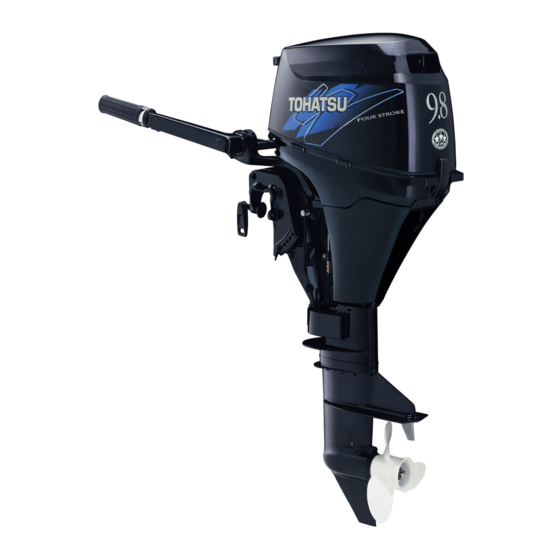
- Page 1 OWNER’S MANUAL MANUEL DE L’UTILISATEUR MANUAL DEL PROPIETARIO BENUTZERHANDBUCH 6A3Z 9.8A3 OB No.003-11113-0...
- Page 3 OWNER’S MANUAL 6A3Z 9.8A3 Original instructions OB No.003-11113-0...
- Page 4 INJURY OR DEATH. KEEP THIS MANUAL IN A SAFE LOCATION FOR FUTURE REFERENCE. Copyright © 2015 Tohatsu Corporation. All rights reserved. No part of this manual may be reproduced or transmitted in any from or by any means without the express written permission of Tohatsu Corporation.
- Page 5 ENOM00006-A To You, Our Customer Thank you for selecting a TOHATSU outboard motor. You are now the proud owner of an excellent outboard motor that will service you for many years to come. This manual should be read in its entirety and the inspection and maintenance procedures described later in this manual should be followed carefully.
-
Page 6: Serial Number
ENOM00005-A Serial Number In the space below, please record the outboard motor's serial number (indicated both on the bottom cowl and on the cylinder block). The serial number will be needed when order- ing parts, and when making technical or warranty inquiries. Serial Number: ENOF01401-0 ENOF01400-0... - Page 7 ENOM00007-0 NOTICE: DANGER/WARNING/CAUTION/Note Before installing, operating or otherwise handling your outboard motor, be sure to thor- oughly read and understand this Owner's Manual and carefully follow all of the instruc- tions. Of particular importance is information preceded by the words “DANGER,” “WARNING,”...
-
Page 9: Table Of Contents
CONTENTS 1. GENERAL SAFETY INFORMATION ....... 10 2. SPECIFICATIONS ..........12 3. - Page 10 12. TOOL KIT AND SPARE PARTS ........83 13.
- Page 11 INDEX 1 GENERAL SAFETY INFORMATION 2. SPECIFICATIONS 3. PARTS NAME 4. LABEL LOCATIONS 5. INSTALLATION 6. PRE-OPERATING PREPARATIONS 7. ENGINE OPERATION 8. REMOVING AND CARRYING THE OUTBOARD MOTOR 9. ADJUSTMENT 10. INSPECTION AND MAINTENANCE 11. TROUBLESHOOTING 12. TOOL KIT AND SPARE PARTS 13.
-
Page 12: General Safety Information
GENERAL SAFETY INFORMATION ENOM00009-0 SAFE OPERATION OF BOAT As the operator/driver of the boat, you are responsible for the safety of those aboard and those in other boat around yours, and for following local boating regulations. You should be thoroughly knowledgeable on how to correctly operate the boat, outboard motor, and accessories. - Page 13 GENERAL SAFETY INFORMATION ENOM00010-0 SERVICING, REPLACEMENT PARTS & LUBRICANTS We recommend that only an authorized service shop perform service or maintenance on this outboard motor. Be sure to use genuine parts, genuine lubricants, or recommended lubricants. ENOM00011-A MAINTENANCE As the owner of this outboard motor, you should be acquainted with correct maintenance procedures following maintenance section of this manual (See page 59).
-
Page 14: Specifications
SPECIFICATIONS ENOM00810-A MODEL FEATURE Model F6A3 F8A3 F9.8A3 Type Transom heights Tiller Handle Remote Control Power Tilt Mnual tilt *1: Option ENOM00811-A MODEL NAME EXAMPLE F 9.8A3 EPTL Model descrip- Horse Product Starter Steering Tilt system Shaft length tion power generation system system... - Page 15 Operator Sound Pressure 77.2 (ICOMIA 39/94) dB (A) Hand Vibration Level — (ICOMIA 38/94) m/sec2 Remark: Specifications subject to change without notice. *1 With propeller, with battery cable. Tohatsu outboard is power rated in accordance with ISO8665 (propeller shaft output).
- Page 16 Operator Sound Pressure 77.2 (ICOMIA 39/94) dB (A) Hand Vibration Level — (ICOMIA 38/94) m/sec2 Remark: Specifications subject to change without notice. *1 With propeller, with battery cable. Tohatsu outboard is power rated in accordance with ISO8665 (propeller shaft output).
- Page 17 Operator Sound Pressure 77.2 (ICOMIA 39/94) dB (A) Hand Vibration Level — (ICOMIA 38/94) m/sec2 Remark: Specifications subject to change without notice. *1 With propeller, with battery cable. Tohatsu outboard is power rated in accordance with ISO8665 (propeller shaft output).
-
Page 18: Parts Name
PARTS NAME ENOM00820-0 MF, EF, EP ENOF01402-0 Tilt Handle Splash Plate Stop Switch *1 Top Cowl Thrust Rod Stop Switch Lanyard Bottom Cowl Clamp Bracket Choke Konob Cooling Water Check Port Clamp Screw Fuel Connector Oil Drain Plug Tiller Handle *1 Starter Switch *2 Water Plug Throttle Grip *1... - Page 19 PARTS NAME ENOM00020-0 EFT, EPT ENOF01403-0 Tilt Handle Splash Plate Stop Switch *1 Top Cowl Tlim Lock Pin Stop Switch Lanyard Bottom Cowl Clamp Bracket Choke Konob Cooling Water Check Port Clamp Screw Fuel Connector Oil Drain Plug Tiller Handle *1 Starter Switch Water Plug Throttle Grip *1...
- Page 20 PARTS NAME ENOM00822-0 Remote control box & Fuel tank ENOF01404-0 Control Lever Fuel gauge Neutral lock arm Air vent screw PTT switch Fuel tank cap Free throttle lever Fuel connector (Engine side) Main switch Primer bulb Stop switch Fuel connector (Fuel tank side) Stop switch lock Stop switch lanyard...
-
Page 21: Label Locations
LABEL LOCATIONS ENOM00019-A Warning label locations 3, 4 ENOF01405-0... - Page 22 LABEL LOCATIONS Warning label regarding owner’s man- Warning label regarding position of ual, top cowl, engine stop switch, outboard motor when setting down. engine oil level and unleaded gasoline. ENOF00006-0 Warning label regarding emergency starting (See page 39). ENOF00128-0 Warning label regarding rotating parts, electrical shock and high temperature.
- Page 23 LABEL LOCATIONS Warning regarding gasoline (See page 29). ENOF00005-S Warning regarding gasoline (See page 29). ENOF00005-L...
- Page 24 LABEL LOCATIONS ENOM00019-B CE label locations r o t 4) 5) l a i ENOF01406-0 1. Model code(Model name) 2. Rated power 3. Dry mass weight( Without propeller, with battery cable) 4. Product year 5. Serial No. 6. Manufacture adress 7.
-
Page 25: Installation
INSTALLATION Keep the outboard motor in a vertical posi- ENOM00024-B 1. Mounting the outboard motor on tion when mounting. boat ENOW00006-0 WARNING Most boats are rated and certified in terms of their maximum allowable horsepower, as shown on the boat’s certification plate. Do not equip your boat with an outboard motor that exceeds this limit. - Page 26 INSTALLATION ENON00002-0 Note A rope is not included in the standard accessories. 5−25 mm (0.2−1 in) ENOF01408-0 1. Bottom of hull 2. Anti ventilation plate ENOW00007-0 ENOF00016-0 CAUTION 1. Bolt (8 × 85) 2. Nut Before beginning the running test, check 3.
-
Page 27: Remote Control Device Installation
INSTALLATION ENOM00840-0 2. Remote control device installation ENOW00850-0 Remote control box location 1, 2 ENOF00841-0 ENOF00508-0 View A Install the remote control box in a position ENOW00008-A where it is easy to reach and operate the CAUTION controls. Make sure there are no obstacles that can Mounting bolts should be installed with the bolt head at inside surface of the interfere with the operation of the remote... -
Page 28: Battery Installation
INSTALLATION contact with your eye, loss of sight. Use safety glasses and rubber gloves. In case battery electrolyte comes in con- tact with: Skin, flush thoroughly with water. Eye, flush thoroughly with water, and then seek immediate medical treatment. In case battery electrolyte is swallowed: Seek immediate medical treatment. - Page 29 INSTALLATION ENOW00015-0 CAUTION Do not use a battery that is not recom- mended. Use of a battery not recom- mended can lead to poor performance of, and/or damage to, the electrical system. ENON00006-A Note Recommended battery: 12V 40AH/5HR, 350 (Cold Cranking Amps (CCA), In case of cold whether: 12V 70AH/5HR (650CCA)) Specifications and features of batteries vary among the manufacturers.
-
Page 30: Pre-Operating Preparations
The fuel system components on your gasoline in the fuel tank for long periods TOHATSU engine will withstand up to 10% should be avoided. Long periods of stor- age, common to boats, create unique prob- ethyl alcohol (hererinafter referred to as the lems. -
Page 31: Fuel Filling
PRE-OPERATING PREPARATIONS age if alcohol has washed protective oil When or before refueling: films from internal components. Be sure to remove the static electricity charged in your body before refueling. The sparks due to static electricity may ENOW00018-0 cause explosion of flammable gasoline. WARNING Stop the engine, and do not start the engine during refueling. -
Page 32: Engine Oil Recommendation
PRE-OPERATING PREPARATIONS ENOF00417-0 ENOF01409-0 1. Air vent screw 2. Fuel tank cap Use only high quality 4-stroke engine oil to insure performance and prolonged engine 2. Open the fuel tank cap slowly. life. 3. Fill the fuel carefully not to over flow. The SAE oil viscosity 10W-30 or 10W-40 FC-W outboard motor engine oil is recom- mended. -
Page 33: Break-In
PRE-OPERATING PREPARATIONS ]ENOM00033-A 4. Break-In Your new outboard motor and lower unit Always attempt to stay on the windward side of emission. require break-in for the moving compo- n e n t s a c c o r d i n g t o t h e c o n d i t i o n s described in the following time table. -
Page 34: Warning System
PRE-OPERATING PREPARATIONS ENOM00039-0 5. Warning system If outboard motor encounters an abnormal condition of fault, the warning horn will emit a continuous beep or intermittent short beeps and the warning lamp (LED) will synchronize with the horn and engine speed will be limited (engine will not be ENOF00851-A stopped). - Page 35 PRE-OPERATING PREPARATIONS ENOM00041-C Warning indicators, faults and remedy Warning indicators Description of faults Remedy Sound Lamp (LED) On for several Normal system test when start up sec.l Engine speed exceeds maximum High speed ESG allowable RPM Continuous Low speed ESG Low oil pressure Remarks *1: In this case, oil pressure switch is “ON”.
- Page 36 PRE-OPERATING PREPARATIONS Remedy Reduce the throttle to less than half opening, and move to safe place quickly, and stop the engine. Check the propeller for bent or dam- aged blades. Consult an authorized dealer if engine shows the same result even after replacing propeller with new one.
-
Page 37: Engine Operation
ENGINE OPERATION ENOM00042-0 tank is raised by heat from sources such as sun light. Before starting 1. Full open the air vent screw on the fuel ENOW00022-A tank cap. CAUTION The engine oil is drained for shipping from the factory. Be sure to fill the engine to the proper level before starting engine. -
Page 38: Starting The Engine
ENGINE OPERATION ENOF00861-A ENOF00863-0 1. Pull 2. Insert 1. Over 10 cm (4 in.) 4. Squeeze primer bulb until it becomes stiff to feed fuel to vapor separator. ENOW00036-0 Direct arrow mark upward when prim- CAUTION ing. Be sure to stop engine immediately if cool- ing water check port is not discharging water, and check if cooling water intake is blocked. -
Page 39: Tiller Handle Type
ENGINE OPERATION down or causing passenger(s) to be thrown 4. Set the control lever in the Neutral overboard. position. Tiller handle type 1. Be sure to install the stop switch lock to the stop switch, and attach the stop switch lanyard securely to the operator or to the operator's PFD (Personal Flo- tation Device.) ENOF00518-0... - Page 40 ENGINE OPERATION 6. Pull the starter handle slowly until you crank engine again after 10 seconds or more. feel engagement, keep pulling till you feel less resistance. Then pull it quickly. repeat if necessary until started. 5. Check the cooling water from cooling water check port.
-
Page 41: Emergency Starting
ENGINE OPERATION 6. Stop pushing the key when the engine has started. The key returns to the original position, automatically. 7. Returns the Free accel lever to close position. 8. Confirm warning lamp light up and then go off after engine has started. ENOF00870-0 1. - Page 42 ENGINE OPERATION 3. Remove the bolts (3 pcs) and remove Be careful that your clothes or other items do not get caught in the rotating the recoil starter. engine parts. To prevent accident and injury by rotat- ing parts, do not re-attach flywheel cover and the top cowl after the engine has been started.
-
Page 43: Warming Up The Engine
ENGINE OPERATION ENOW00860-0 CAUTION Be sure to keep the harness away from the rotation parts. 6. Be sure to install the stop switch lock to the stop switch, and attach the stop switch lanyard securely to the operator or to the operator's PFD (Personal Flo- ENOF00528-0 tation Device.) 1. -
Page 44: Forward, Reverse, And Acceleration
ENGINE OPERATION Arrange the tether so that will not be caught by any object when pulled. Be careful not to pull the tether acciden- tally during cruising. Unintentional stop of engine can cause loss of control of outboard motor. Rapid loss of engine power can lead to falling down or caus- ing passenger(s) to be thrown over- board. - Page 45 ENGINE OPERATION stop engine, shift to neutral, and restart 1. Shift lever engine to warm up. Forward 1. Turn the throttle grip to reduce engine ENON00014-0 Note speed. Frequent shifting to forward or reverse can 2. When the engine reaches trolling (or accelerate wear or degradation of parts.
-
Page 46: Stopping The Engine
ENGINE OPERATION 2. Further forward motion will open the ENOM0900-0 Side mount RC type throttle. ENOW00867-0 Reverse WARNING 1. Quickly pull the control lever to the Reverse (R) position at 32°, where the Sudden acceleration and deceleration may gear is connected, while lifting up on cause passenger(s) to be thrown over- the lock button located under the con- board or falling down. - Page 47 ENGINE OPERATION Side mount RC type the boat to be thrown forward due to iner- tial force. 1. Put the control lever in the Neutral position and run the engine for 2-3 Tiller handle type minutes at idling speed for cooling 1.
-
Page 48: Steering
ENGINE OPERATION Emergency engine stopping Remove stop switch lock to stop the engine. ENOF00891-0 ENOM00920-0 6. Steering ENOW00870-0 WARNING ENOF00569-0 Sudden steering may cause passenger(s) to be thrown overboard or falling down. Tiller handle type Right turn Move the tiller handle to the left Left turn Move the tiller handle to the right. -
Page 49: Trim Angle
ENGINE OPERATION ate the switch during cruising, or control of boat may be lost. The trim angle of the outboard motor can be adjusted to suit the transom angle of the hull, and load conditions. Choose an appropriate trim angle that will allow the anti-ventilation plate to run parallel to the water surface during operation. - Page 50 ENGINE OPERATION Trim angle adjustment (Manual tilt type) The transom angle adjustment 1. Stop the engine. 2. Shift into neutral. 3. Raise the outboard motor to the tilt up position. 4. Change the thrust rod position as fol- ENOF00053-0 lowing picture. ENOF01238-0 ENOF00532-0 1.
-
Page 51: Tilt Up And Down
ENGINE OPERATION 4. Change the trim lock pin position as 2. Higher 3. Lower following picture. 5. Reinstall the tilt lock pin securely. 6. Operate the Power Tilt switch and lower the outboard. ENOM00060-A 8. Tilt up and down ENOW00055-0 WARNING ENOF01425-0 1. - Page 52 ENGINE OPERATION lever toward you to release the tilt-lock. ENON00921-0 Note Then lower the motor slowly. Before tilting the outboard motor up, after stopping the motor leave it in the running position for about a minute to allow water to drain from inside the engine.
- Page 53 ENGINE OPERATION ENOM00940-0 Manual relief valve If the battery is dead, and the power tilt switch thus inoperative, open the manual valve completely in the Manual direction. This will allow manual tilting of the out- board motor. ENOW00872-0 WARNING Make sure the manual relief valve is closed before operating the outboard motor.
-
Page 54: Shallow Water Operation
ENGINE OPERATION Manual tilt type (MF, EF type) ENOM00068-A 9. Shallow water operation Shallow water running position: 1. With the shift lever in Neutral or For- ward, tilt the motor up slowly by about ENOW00051-0 40° and then lower the tilt lever for set- WARNING ting at the shallow water running posi- During shallow water operation, be careful... - Page 55 ENGINE OPERATION ENOM00541-A ENOM00069-A Power Tilt type Manual tilt type (EP type) 1. Operate the Power Tilt switch and tilt Shallow water running position the outboard motor up into desired 1. Stop the engine. shallow water running position. 2. Shift the outboard into forward. 3.
-
Page 56: Removing And Carrying The Outboard Motor
REMOVING AND CARRYING THE OUTBOARD MOTOR ENOM00070-B Fuel leakage is a fire or explosion hazard, which can cause serious injury or death. 1. Removing the outboard motor ENOW00065-0 ENOW00064-0 WARNING CAUTION Close air vent screw of fuel tank before Engine may be hot immediately after oper- carrying or storing outboard motor and fuel ating and could cause burns if touched. -
Page 57: Traillering
REMOVING AND CARRYING THE OUTBOARD MOTOR Fuel leakage is a fire or explosion hazard, which can cause serious injury or death. ENOF00075-1 ENOW00068-0 WARNING Close air vent screw of fuel tank and fuel cock before carrying or storing outboard ENOF01416-0 motor and fuel tank, or fuel may leak, ENON00021-A potentially catching fire. - Page 58 REMOVING AND CARRYING THE OUTBOARD MOTOR ENOF00073-A 1. Ground clearance should be provided sufficiently. 2. Transom saver bar ENOW00067-0 WARNING Do not go under outboard motor tilted up even if it is supported by support bar, or accidental fall of outboard motor could lead to severe personal injury.
-
Page 59: Adjustment
ADJUSTMENT ENOM00073-0 2. Lighter 3. Heavier 1. Steering friction EENOM00074-A 2. Throttle grip friction Tiller handle type ENOW00074-A ENOW00074-B WARNING WARNING Do not overtighten the steering friction Do not overtighten the throttle adjustment lever it could result in difficulty of move- screw or it could result in difficulty of ment resulting in the loss of control caus- movement resulting in the loss of control... -
Page 60: Trim Tab Adjustment
ADJUSTMENT counter-clockwise to decrease it. I f s t r a i g h t - l i n e c r u i s i n g c a n n o t b e achieved, adjust the trim tab located under Side mount type the anti-ventilation plate. -
Page 61: Inspection And Maintenance
INSPECTION AND MAINTENANCE ENOM00077-0 Care of your outboard motor To keep your outboard motor in the best operating condition, it is very important that you perform daily and periodic main- tenance as suggested in the maintenance schedules that follow. ENOW00077-0 CAUTION Your personal safety and that of your passengers depends on how well you... -
Page 62: Daily Inspection
INSPECTION AND MAINTENANCE ENOM00551-0 1. Daily Inspection Perform the following checks before and ENOW00078-0 after use. WARNING Do not use outboard motor if any abnor- mality is found during pre-operation check or it could result in severe damage to the motor or severe personal injury. - Page 63 INSPECTION AND MAINTENANCE ENOM00081-A ENON00024-0 Oil level checking Note If the oil level is low, or too high, the life of The oil level should be checked when the the engine will be shortened significantly. engine is cold. 1. Stop the engine and set it in a vertical ENON00025-0 position.
- Page 64 INSPECTION AND MAINTENANCE level, use fresh water to remove salt, chemicals or mud from exterior and cool- ing water passage after every cruising or before storing outboard motor for long time. Before flushing, remove the propeller and the forward thrust holder. ENOM00085-A Flushing attachment ENOW00922-0...
- Page 65 10 cm (4 in.) above the anti ventilation If the fuse continues to blow, request an plate. authorized Tohatsu dealer to inspect the And be sure to remove the propeller, when outboard motor. starting the engine in the test tank. (See 1.
- Page 66 INSPECTION AND MAINTENANCE 2. Remove the engine cover. 3. Remove the fuse box lid. 4. Remove the fuse and check it. If the fuse is blown, replace it with a fuse of the same specified rating. The out- board motor is supplied with spare fuses in the spare fuse holder.
-
Page 67: Periodic Inspection
INSPECTION AND MAINTENANCE ENOM00555-0 2. Periodic Inspection It is important to inspect and maintain your outboard motor regularly. At each interval on the chart below, be sure to perform the indicated servicing. Maintenance intervals should be determined according to the number of hours or number of months, whichever comes first. - Page 68 INSPECTION AND MAINTENANCE ENON00030-0 Note Your outboard motor should receive careful, and complete inspection at 300 hours. This is the best time for major maintenance procedures to be carried out. ENOM00091-A ENOW00933-0 Engine oil replacement CAUTION ENOW00091-0 Engine oil mixed with dust or water will CAUTION dramatically shorten the life of the engine.
- Page 69 INSPECTION AND MAINTENANCE ENON00028-A Note If a torque-wrench is not available when you are fitting a oil filter, a good estimate of the correct torque is 3/4 to 1 a turn past finger- tight. Have the oil filter adjusted to the cor- rect torque as soon as possible with a torque-wrench.
- Page 70 INSPECTION AND MAINTENANCE If engine oil is contaminated with fuel, emitting strong fuel smell, consult dealer. Some oil dilution is normal if engine is idled or trolled for long periods, espe- cially in cooler water temperatures. ENOM00093-A Fuel filters and fuel tank cleaning ENOW00093-A WARNING ENOF00560-0...
- Page 71 INSPECTION AND MAINTENANCE ENOM00096-A Be sure to lock outboard motor if it is Fuel filter (for fuel tank) tilted up, or accidental fall of outboard Water or dirt in the fuel tank will cause motor could lead to severe personal injury.
-
Page 72: Propeller Replacement
INSPECTION AND MAINTENANCE fire prevention and environment protection regulations. ENON00032-0 Note If water in the oil, giving it a milky colored appearance. Contact your dealer. ENON00033-0 Note Use genuine gear oil or the recommended one (API GL-5: SAE #80 to #90). Required volume: approx. - Page 73 INSPECTION AND MAINTENANCE motor's performance, and cause engine 6. Tighten the propeller nut to specified trouble. torque, and align one of grooves to 1. Put a piece of wood block between propeller shaft hole. propeller blade and anti-ventilation Propeller nut torque: plate to hold propeller.
- Page 74 INSPECTION AND MAINTENANCE 2. Remove the top cowl. the correct torque as soon as possible with a torque-wrench. 3. Remove the spark plug caps. 4. Remove the spark plugs by turning it counter-clockwise, using a 5/8" (16 mm) socket wrench and handle that is provided in tool bag.
-
Page 75: Anode Replacement
INSPECTION AND MAINTENANCE ENOM00088-A Anode replacement A sacrificial anode protects the outboard motor from electrolytic corrosion. Anode is located on the gear case, cylinder etc.. When the anode is eroded more than 1/3 of origi- nal size, replace it. ENON00029-0 Notes Never grease or paint the anode. - Page 76 INSPECTION AND MAINTENANCE ENOM00089-B Recommended oil Power Tilt oil checking Use an automatic transmission fluid or ENOW00088-0 equivalent. WARNING Recommended oils are as shown below. ATF Dexron III Be sure that outboard motor is secured to transom or service stand, or acciden- Air purging from the Power Trim and tal drop or fall of outboard motor could lead to severe personal injury.
- Page 77 INSPECTION AND MAINTENANCE ENOM00960-0 Grease point Apply water proof grease to the parts shown below. ENOF01429-0...
-
Page 78: Off-Season Storage
INSPECTION AND MAINTENANCE 2. Remove the fuel hose from the out- ENOM00100-A 3. Off-season storage board motor. 3. Drain all fuel from the fuel hoses, fuel ENOW00934-0 pump and carburetor (See page 78), WARNING and clean these parts. Keep in mind that if gasoline is kept in Be sure to disconnect fuel connector the carburetor for a long time, gum and except when operating engine. -
Page 79: Adding A Fuel Stabilizer
INSPECTION AND MAINTENANCE 9. Stand the outboard motor up vertically in a dry place. ENOF01415-0 ENOM00950-0 Adding a fuel stabilizer When adding a fuel stabilizer additive (commercially available), first fill the fuel tank with fresh fuel. If the fuel tank is only partially filled, air in the tank can cause the fuel to deteriorate during storage. - Page 80 INSPECTION AND MAINTENANCE 8. Check the drained fuel for the pres- ENOM00970-0 Fuel system draining ence of water or other contaminants. If ENOW00028-A either is present, reassemble the out- WARNING board motor, refill the carburetor with fuel, and then drain the fuel again. For details on handling fuel, contact an Repeat this procedure until no water or authorized dealer.
-
Page 81: Pre-Season Check
INSPECTION AND MAINTENANCE 5. Recharge the battery once a month to 9. Run the engine for 10 minutes at half prevent it from discharging and the throttle. The oil used for storage inside the engine will be circulated out to electrolyte from deteriorating. -
Page 82: Cold Weather Precautions
INSPECTION AND MAINTENANCE ENOM00106-A 6. Cold weather precautions If you moor your boat in cold weather at temperatures below 0°C (32°F), there is the danger of remained water freezing in the cooling water pump, which may dam- age the pump, impeller, etc. To avoid this problem, submerge the lower half of the outboard motor into the water. -
Page 83: Troubleshooting
TROUBLESHOOTING ENOM00561-0 If you encounter a problem, consult the check list below to determine the cause and to take the proper action. An authorized dealer will always be happy to provide any assistance and information. Possible cause Empty fuel tank Incorrect connection of fuel system Air entering fuel line Deformed or damaged fuel hose... - Page 84 TROUBLESHOOTING Possible cause Low compression Carbon deposits in the combustion chamber Incorrect valve clearance Low oil pressure/level Low oil level Use of improper oil Oil deterioration Clogged oil strainer Faulty oil pump Incorrect adjustment of throttle link Insufficient cooling water flow, clogged or defec- tive pump Faulty thermostat Cavitation or ventilation...
-
Page 85: Tool Kit And Spare Parts
TOOL KIT AND SPARE PARTS ENOM00562-0 The following a list of the tools and spare parts provided with the motor. Items Quantity Remark Tool bag Pliers Socket wrench 10 × 13 mm Service tools Socket wrench 16 mm (spark plug) Socket wrench handle Screwdrivers Cross-and straight-point... -
Page 86: Propeller Table
PROPELLER TABLE ENOM00111-0 Use a genuine propeller. A propeller must be selected so that the engine rpm measured at wide open throttle while cruising is within the recommended range. 5000–6000 rpm Propeller Size (Diameter × pitch) Propeller Mark No. of Blades inch Light boats 8.9 ×... - Page 90 OWNER’S MANUAL 6A3Z 9.8A3 003-11113-0 1412NB Printed in Japan...
- Page 91 MANUEL DE L'UTILISATEUR 6A3Z 9.8A3 Notice originale OB No.003-11113-0...
- Page 92 MORTEL. CONSERVEZ CE MANUEL DANS UN LIEU SÛR POUR TOUTE RÉFÉRENCE ULTÉRIEURE. Copyright © 2015 Tohatsu Corporation. Tous droits réservés. Il est strictement interdit de reproduire ou de diffuser tout ou partie de ce manuel, sous quelque forme ou de quelque manière que ce soit, sans...
- Page 93 CONFORMÉMENT À LA LÉGISLATION EN VIGUEUR, VOTRE MOTEUR HORS-BORD NE SERA PAS COUVERT PAR LA GARANTIE LIMITÉE APPLICABLE SI CETTE PROCÉDURE N'EST PAS SUIVIE. ENOM00003-0 INSPECTION AVANT LIVRAISON Assurez-vous que le produit a été inspecté par un distributeur TOHATSU agréé avant d'en prendre livraison.
- Page 94 ENOM00005-A Numéro de série Veuillez enregistrer, dans l'espace ci-dessous, le numéro de série du moteur hors-bord (mentionné aussi bien sur la cuvette inférieure que sur le bloc-cylindres). Il faut mentionner le numéro de série lors de la commande de pièces et lors de toute demande de renseignements techniques ou relatifs à...
- Page 95 ENOM00007-0 NOTIFICATION : DANGER / AVERTISSEMENT / CONSEIL DE PRUDENCE / Remarque Avant l'installation, la mise en service ou toute autre manipulation de votre moteur hors- bord, veillez à lire et à comprendre l'intégralité de ce manuel d'utilisation, et à suivre attentivement toutes les instructions.
- Page 97 TABLE DES MATIÈRES 1. INFORMATIONS GÉNÉRALES DE SÉCURITÉ ..... . 10 2. CARACTÉRISTIQUES TECHNIQUES ......12 3.
- Page 98 12. KIT D'OUTILS ET PIÈCES DÉTACHÉES ......86 13. TABLEAU DES HÉLICES ........87...
-
Page 99: Table Des Matières
TABLE DES MATIÈRES 1 INFORMATIONS GÉNÉRALES DE SÉCURITÉ 2. CARACTÉRISTIQUES TECHNIQUES 3. NOM DES PIÈCES 4. EMPLACEMENT DES ETIQUETTES 5. INSTALLATION 6. MESURES À PRENDRE AVANT LE DÉMARRAGE 7. FONCTIONNEMENT DU MOTEUR 8. DÉPOSE ET TRANSPORT DU MOTEUR HORS-BORD 9. RÉGLAGES 10. -
Page 100: Informations Générales De Sécurité
INFORMATIONS GÉNÉRALES DE SÉCURITÉ ENOM00009-0 CONDUITE EN TOUTE SÉCURITÉ D'UN BATEAU En votre qualité d'opérateur / de conducteur du bateau, vous êtes responsable de la sécurité des personnes à bord et de celles présentes à bord des autres bateaux à proximité... - Page 101 INFORMATIONS GÉNÉRALES DE SÉCURITÉ ENOM00010-0 ENTRETIEN, PIÈCES DE RECHANGE ET LUBRIFIANTS Nous recommandons que seul un atelier d'entretien agréé procède aux réparations ou à la maintenance du moteur hors-bord. Veillez à utiliser des pièces d'origine et les lubrifiants prescrits ou recommandés. ENOM00011-A MAINTENANCE Le propriétaire du moteur hors-bord doit être au courant des procédures de maintenance...
-
Page 102: Caractéristiques Techniques
CARACTÉRISTIQUES TECHNIQUES ENOM00810-A CARACTÉRISTIQUES DES MODÈLES Modèle F6A3 F8A3 F9.8A3 Type Hauteurs tableau arrière Poignée de barre Commande à distance Dispositif de relevage Relevage manuel *1: En option ENOM00811-A EXEMPLE POUR UN MODÈLE F 9.8A3 EPTL Description du Puissan Génération Système du Système Système de... - Page 103 (ICOMIA 38/94) m/sec2 Remarque : Les caractéristiques techniques peuvent être modifiées sans avis préalable. *1 Avec hélice, avec le câble de batterie. Le moteur hors-bord Tohatsu est réglé à puissance nominale conformément à la norme ISO8665 (sortie de l'arbre d'hélice).
- Page 104 (ICOMIA 38/94) m/sec2 Remarque : Les caractéristiques techniques peuvent être modifiées sans avis préalable. *1 Avec hélice, avec le câble de batterie. Le moteur hors-bord Tohatsu est réglé à puissance nominale conformément à la norme ISO8665 (sortie de l'arbre d'hélice).
- Page 105 (ICOMIA 38/94) m/sec2 Remarque : Les caractéristiques techniques peuvent être modifiées sans avis préalable. *1 Avec hélice, avec le câble de batterie. Le moteur hors-bord Tohatsu est réglé à puissance nominale conformément à la norme ISO8665 (sortie de l'arbre d'hélice).
-
Page 106: Nom Des Pièces
NOM DES PIÈCES ENOM00820-0 MF, EF, EP ENOF01402-0 Poignée de levage Pare-gouttes Lampe témoin Capot supérieur Tige de butée Interrupteur d'arrêt *1 Capot inférieur Étrier de fixation Cordon de sécurité coupe- Orifice de contrôle de l'eau de Vis de serrage circuit refroidissement Poignée de barre *1... - Page 107 NOM DES PIÈCES ENOM00020-0 EFT, EPT ENOF01403-0 Poignée de levage Pare-gouttes Bouchon de remplissage Capot supérieur Goupille de verrouillage de d'huile Capot inférieur relevage Lampe témoin Orifice de contrôle de l'eau de Étrier de fixation Interrupteur d'arrêt *1 refroidissement Vis de serrage Cordon de sécurité...
- Page 108 NOM DES PIÈCES ENOM00822-0 Boîtier de la commande à distance et réservoir à carburant ENOF01404-0 Levier de commande Jauge de carburant Bras de verrouillage du point Vis d'évent mort Bouchon du réservoir à Interrupteur autobloquant (PTT) carburant Manette des gaz au point mort Raccord de carburant (côté...
-
Page 109: Emplacements Des Étiquettes
EMPLACEMENT DES ÉTIQUETTES ENOM00019-A Emplacement des étiquettes de mise en garde 3, 4 ENOF01405-0... - Page 110 EMPLACEMENT DES ÉTIQUETTES Étiquette de mise en garde relative au Étiquette de mise en garde sur le manuel de l'’utilisateur, au capot positionnement du moteur hors-bord supérieur, à l'interrupteur d'arrêt du lorsqu'il est détaché de l'embarcation. moteur, au niveau de l'huile moteur et à...
- Page 111 EMPLACEMENT DES ÉTIQUETTES Étiquette de mise en garde sur l'essence (voir page 29) ENOF00005-S Étiquette de mise en garde sur l'essence (voir page 29) ENOF00005-L...
- Page 112 EMPLACEMENT DES ÉTIQUETTES ENOM00019-B Emplacement des étiquettes CE r o t 4) 5) l a i ENOF01406-0 1. Code du modèle (nom du modèle) 2. Puissance nominale 3. Poids de la masse sèche (sans l'hélice, avec le câble de batterie) 4.
-
Page 113: Installation
INSTALLATION ENOM00024-B sur l'eau pour vérifier que les fixations sont solidement assujetties. 1. Montage du moteur hors-bord Le montage du moteur hors-bord doit sur le bateau être réalisé à l'aide d'un appareil de levage ou palan de capacité suffisante ENOW00006-0 par du personnel technique formé. - Page 114 INSTALLATION ENOM00026-0 moteur à de telles conditions peut Adaptation au tableau arrière sérieusement endommager celui-ci. Assurez-vous que la plaque anti-cavitation du moteur hors-bord est à 5–25 mm (0.2– ENOM00830-A 1 in) au-dessous de la partie inférieure de Boulons de fixation la coque.
-
Page 115: Installation Du Dispositif De Commande À Distance
INSTALLATION Serrez les boulons suffisamment afin d'éviter une chute du moteur hors-bord. ENON00003-0 Remarques 1. Appliquez un agent isolant tel que du silicone entre les boulons et le panneau du tableau arrière avant de serrer les boulons. 2. Assurez-vous de serrer les écrous des boulons d'assemblage couple... -
Page 116: Installation De La Batterie
INSTALLATION ENOW00850-0 ENOM00029-A Longueur du câble de la commande à 3. Installation de la batterie distance ENOW00100-A ENOW00012-0 CONSEIL DE PRUDENCE AVERTISSEMENT Veillez à ce que les câbles de la commande L ' é l e c t r o l y t e d e l a b a t t e r i e e s t u n e à... - Page 117 INSTALLATION 1. Placez le caisson porte-batterie dans ne pas fumer à proximité de la batterie lorsqu'elle est en charge. une position adéquate à l'écart de Ne pas charger la batterie quand le toute projection d'eau. Assujettissez niveau d'électrolyte est bas. Sinon la fermement le caisson et la batterie afin batterie pourrait être endommagée et qu'ils ne bougent pas en cas de...
-
Page 118: Mesures À Prendre Avant Le Démarrage
CONSEIL DE PRUDENCE résistent à de l'essence contenant jusqu'à 10 % d'alcool éthylique (repris ci-après En utilisant un moteur TOHATSU avec de sous le nom d'« éthanol »). Si l'essence l'essence contenant de l'alcool, il faut dans votre région contient de l'éthanol, é... -
Page 119: Remplissage Du Réservoir À Carburant
MESURES À PRENDRE AVANT LE DÉMARRAGE essence sont généralement consommés ENOW00028-A a v a n t q u ' i l s n e p u i s s e n t a b s o r b e r AVERTISSEMENT suffisamment d'humidité... -
Page 120: Recommandations Relatives À L'huile Moteur
MESURES À PRENDRE AVANT LE DÉMARRAGE Si le réservoir à carburant a été démonté p o u r l e n e t t o y a g e , r e m o n t e z - l e correctement. - Page 121 MESURES À PRENDRE AVANT LE DÉMARRAGE L'huile SAE de viscosité 10W-30 ou l'huile moteur pour moteur hors-bord 10W-40 FC-W est recommandée. Vous pouvez également utiliser des huiles d e c a t é g o r i e A P I S H , S J , o u S L . Sélectionnez, dans le tableau ci-après, la viscosité...
-
Page 122: Rodage
MESURES À PRENDRE AVANT LE DÉMARRAGE ]ENOM00033-A 4. Rodage Le nouveau moteur hors-bord et le bloc de Veillez à ce que la zone périphérique soit bien ventilée. propulsion nécessitent un rodage des Essayez toujours de vous tenir de telle composants mobiles suivant les durées sorte que la direction du vent éloigne les re c o m m a n d é... -
Page 123: Système D'alarme
MESURES À PRENDRE AVANT LE DÉMARRAGE ENOM00039-0 5. Système d'alarme Si le moteur hors-bord présente une défaillance ou un problème, l'avertisseur sonore émettra un bip continu ou une série de bips intermittents. Dans ce cas, la l a m p e t é m o i n ( D E L ) s ' a l l u m e r a e n synchronisation avec l'avertisseur et la ENOF00851-A vitesse du moteur sera réduite (le moteur... - Page 124 MESURES À PRENDRE AVANT LE DÉMARRAGE ENOM00041-C Signaux d'alarme, défaillances et remèdes Signal d'alarme Description de la défaillance Remède Lampe témoin Signal sonore (DEL) Reste allumé Test normal du système au pour plusieurs démarrage secondes.l Le régime du moteur dépasse les ESG haute vitesse TR/MIN maximaux autorisés.
-
Page 125: Fonctionnement Du Moteur
FONCTIONNEMENT DU MOTEUR ENOM00042-0 ENOM00044-A Avant le démarrage 1. Alimentation en carburant ENOW00022-A ENOW00029-A CONSEIL DE PRUDENCE AVERTISSEMENT L ' h u i l e m o t e u r e s t v i d a n g é e p o u r En ouvrant le bouchon du réservoir de l'expédition au départ de l'usine. -
Page 126: Démarrage Du Moteur
FONCTIONNEMENT DU MOTEUR contraire, le carburant pourrait déborder. Dans le cas contraire, le carburant pourrait déborder. ENOM00045-C 2. Démarrage du moteur ENOW00036-A CONSEIL DE PRUDENCE P o u r é v i t e r t o u t e s u rc h a u ff e e t t o u t ENOF00514-0 endommagement de la pompe à... - Page 127 FONCTIONNEMENT DU MOTEUR Modèle à poignée de barre distributeur agréé si la cause du problème n'est pas identifiée. 1. Assurez-vous de placer le mécanisme de verrouillage sur l'interrupteur d'arrêt ENOW00032-A et attachez correctement le cordon de CONSEIL DE PRUDENCE sécurité coupe-circuit à l'opérateur ou à...
- Page 128 FONCTIONNEMENT DU MOTEUR 4. Positionnez le levier de commande au 6. Tirez la poignée du lanceur jusqu'à ce point mort (N). que vous sentiez une prise, continuez à tirer jusqu'à ce que vous sentiez la résistance faiblir, Ensuite, retirez-la rapidement. Répétez l'opération jusqu'à...
- Page 129 FONCTIONNEMENT DU MOTEUR 4. Soulevez levier démarrage du moteur et / ou pourrait endommager le mécanisme. d'accélération au point mort (moteur Si le moteur ne démarre pas après 5 chaud et moteur froid). secondes, repositionnez la clé de contact sur “ON”, puis redémarrez le moteur après 10 secondes ou plus.
- Page 130 FONCTIONNEMENT DU MOTEUR 1. Position ON ENOM00042-A Démarrage d'urgence 2. Position START 3. Position OFF ENOW00099-A 4. Poussez pour actionner le bouton du starter AVERTISSEMENT 6. Cessez de pousser la clé de contact après démarrage du moteur. Lorsque la corde de secours du lanceur est utilisée pour démarrer le moteur : La clé...
- Page 131 FONCTIONNEMENT DU MOTEUR 2. Retirez le câble du démarreur du 5. Faites une boucle à l'autre extrémité lanceur à rappel en dévissant la vis de la corde de secours du lanceur et depuis le câble du démarreur. attachez-y la clé à douille fournie avec la boîte à...
-
Page 132: Mise En Température Du Moteur
FONCTIONNEMENT DU MOTEUR ENOM00518-0 ENOM00043-A Si le solénoïde du starter ne 3. Mise en température du moteur fonctionne pas (modèles EP et EPT seulement) ENOW00932-0 CONSEIL DE PRUDENCE 1. Enlevez le capot supérieur. Assurez-vous de vérifier que l'eau de 2. Fermez du doigt la plaque du starter. refroidissement sort bien par l'orifice de 3. -
Page 133: Marche Avant, Marche Arrière Et Accélération
FONCTIONNEMENT DU MOTEUR ENOM00046-A s u b m e r s i o n d u b a t e a u e t / o u l'endommagement de la coque. 4. Marche avant, marche arrière et N'enclenchez pas la marche arrière accélération pendant la navigation pour éviter toute perte de contrôle, toute chute des... - Page 134 FONCTIONNEMENT DU MOTEUR ENON00014-0 Remarque De fréquents enclenchements en marche avant ou marche arrière peuvent accélérer l'usure ou la dégradation des pièces. Dans ce cas, remplacez plus souvent l'huile pour e m b a s e p a r r a p p o r t a u x i n t e r v a l l e s spécifiés.
- Page 135 FONCTIONNEMENT DU MOTEUR ENOF01119-0 1. Poignée des gaz ENOM0900-0 Modèle à commande à distance ENOF00877-0 à montage latéral 1. Marche avant (F) 2. Point mort (N) ENOW00867-0 3. Marche arrière (R) 4. Complètement ouvert (marche avant) AVERTISSEMENT 5. Complètement ouvert (marche arrière) 6.
-
Page 136: Arrêt Du Moteur
FONCTIONNEMENT DU MOTEUR Accélération ENOW00867-A CONSEIL DE PRUDENCE Une accélération et décélération soudaine pourrait faire basculer ou projeter les passagers par-dessus bord. Ouvrez graduellement la poignée des gaz ou le levier de commande. ENOF01107-0 1. Poignée des gaz 2. Placez le levier inverseur sur le point mort (Neutral). - Page 137 FONCTIONNEMENT DU MOTEUR Modèle à commande à distance Débranchez les câbles de la batterie après chaque utilisation. à montage latéral 1. Positionnez le levier inverseur au point Arrêt d'urgence du moteur mort et faites tourner le moteur au Retirer le mécanisme de verrouillage de ralenti pendant 2 à...
-
Page 138: Conduite
FONCTIONNEMENT DU MOTEUR v e i l l e z à u t i l i s e r l e m é c a n i s m e d e verrouillage de l'interrupteur d'arrêt d'urgence de rechange. Assurez-vous que le mécanisme de verrouillage de l'interrupteur d'arrêt d'urgence de rechange se trouve bien dans la boîte à... - Page 139 FONCTIONNEMENT DU MOTEUR blessure au cas où le bloc moteur venait à tomber. Une position de relevage incorrecte peut provoquer une perte de contrôle du bateau. Lors de l'essai d'une position de relevage, naviguez d'abord à vitesse réduite pour vérifier que le bateau peut être contrôlé...
- Page 140 FONCTIONNEMENT DU MOTEUR 4. Changer la position de la barre de réglage comme il l'est illustré dans l'image suivante. ENOF00532-0 1. Tige de butée 2. Plus haut 3. Partie inférieure ENOF01238-0 1. Pousser vers l'intérieur 2. Relever la butée 3. Retirer 5.
-
Page 141: Relever Et Abaisser
FONCTIONNEMENT DU MOTEUR 1. Bouton de préréglage 1. Tirer 2. Plus haut ENOM00060-A 3. Partie inférieure 8. Relever et abaisser 5. Réinstallez le bouton de préréglage en ENOW00055-0 toute sécurité. AVERTISSEMENT 6. Abaissez doucement le moteur hors- bord. Ne relevez pas ni n'inclinez le moteur hors- b o r d q u a n d d e s b a i g n e u r s o u d e s passagers se trouvent à... - Page 142 FONCTIONNEMENT DU MOTEUR ENON00921-0 ENOM00063-A Remarque Rabaissement Soulevez doucement le moteur puis tirez le Après avoir arrêté le moteur hors-bord, levier d'inclinaison pour déverrouiller le laissez-le en position de fonctionnement verrou de relevage. pendant environ une minute avant de le relever pour permettre l'écoulement de l'eau Puis baissez doucement le moteur.
- Page 143 FONCTIONNEMENT DU MOTEUR “ON” ou “OFF”. ENOM00940-0 Soupape de décharge manuelle Si le dispositif d'inclinaison et de relevage ne fonctionne pas parce que la batterie est à plat, ouvrez complètement la soupape de décharge manuelle dans la direction Manuel. Cette opération permettra le relevage manuel du moteur hors-bord.
-
Page 144: Utilisation En Eaux Peu Profondes
FONCTIONNEMENT DU MOTEUR ENOW00054-A CONSEIL DE PRUDENCE N'inclinez pas trop le moteur hors-bord l o r s d ' u n e n a v i g a t i o n e n e a u x p e u profondes, car de l'air pourrait être aspiré... - Page 145 FONCTIONNEMENT DU MOTEUR Retour en position de fonctionnement normal 1. Arrêtez le moteur. 2. Placez le moteur en position relevée. 3. Abaissez doucement le moteur hors- bord. ENOF00549-0 1. Levier de relevage 2. Position de fonctionnement en eaux peu profondes ENOM00541-A Type à...
-
Page 146: Dépose Et Transport Du Moteur Hors-Bord
DÉPOSE ET TRANSPORT DU MOTEUR HORS-BORD ENOM00070-B Toute fuite de carburant représente un risque d'incendie ou d'explosion pouvant 1. Dépose du moteur hors-bord entraîner des lésions corporelles graves, voire mortelles. ENOW00064-0 CONSEIL DE PRUDENCE ENOW00065-0 AVERTISSEMENT Le moteur peut être chaud immédiatement après avoir été... -
Page 147: Remorquage
DÉPOSE ET TRANSPORT DU MOTEUR HORS-BORD ENOW00073-A AVERTISSEMENT N'oubliez pas de débrancher le raccord de carburant lorsque le moteur n'est pas en fonctionnement. Toute fuite de carburant représente un risque d'incendie ou d'explosion pouvant entraîner des lésions corporelles graves, voire mortelles. ENOF01416-0 ENON00021-A ENOF00075-1... - Page 148 DÉPOSE ET TRANSPORT DU MOTEUR HORS-BORD Modèle à poignée de barre Pour empêcher le moteur hors-bord de bouger lorsqu'il est fixé sur un bateau pendant le transport de celui-ci sur une remorque, il faut resserrer correctement le levier de friction d'embrayage (page 59). ENOF00073-A 1.
-
Page 149: Réglage
RÉGLAGES ENOM00073-0 2. Plus légère 3. Plus forte 1. Friction de direction EENOM00074-A 2. Friction de la poignée des gaz Modèle à poignée de barre ENOW00074-A ENOW00074-B AVERTISSEMENT AVERTISSEMENT Ne serrez pas trop le levier de friction de Ne serrez pas trop la vis de réglage de la d i re c t i o n c a r c e l a p o u r r a i t re n d re l e poignée des gaz car cela pourrait rendre le mouvement difficile et provoquer une perte... -
Page 150: Réglage De La Dérive
RÉGLAGES commande à distance, tournez la vis de ENOW00075-0 réglage de la friction de la poignée des gaz AVERTISSEMENT sur le devant de la commande à distance. Un réglage incorrect de la dérive peut Tour nez dans le sens contraire des entraîner des problèmes de conduite. -
Page 151: Inspection Et Maintenance
INSPECTION ET MAINTENANCE ENOM00077-0 Entretien du moteur hors-bord Pour maintenir votre moteur hors-bord d a n s l e s m e i l l e u r e s c o n d i t i o n s d e fonctionnement, il est impératif que vous effectuiez une maintenance quotidienne et périodique, conformément au calendrier... -
Page 152: Inspection Quotidienne
INSPECTION ET MAINTENANCE ENOM00551-0 1. Inspection quotidienne Effectuez les contrôles suivants avant et ENOW00078-0 après chaque utilisation du moteur. AVERTISSEMENT N'utilisez en aucun cas le moteur hors- bord sur lequel la moindre anomalie a été détectée lors du contrôle avant mise en m a r c h e a f i n d ' é... - Page 153 INSPECTION ET MAINTENANCE Élément Points à contrôler Remède • Vérifiez que l'anode est correctement installée. Réparez-la, le cas échéant Autres pièces • Vérifiez que l'anode ne présente aucune déformation ni aucun signe de Remplacez-la corrosion. ENOM00081-A 2. Repère inférieur 1500 mL Contrôle du niveau d'huile ENON00024-0 Remarque...
- Page 154 INSPECTION ET MAINTENANCE l ' h u i l e m o t e u r d é p a s s e l a l i m i t e ENOW00920-0 supérieure, ceci peut occasionner des CONSEIL DE PRUDENCE fuites conduisant éventuellement à...
- Page 155 INSPECTION ET MAINTENANCE 4. Mettez le levier inverseur au point mort ENOW00036-A et démarrez le moteur. CONSEIL DE PRUDENCE Continuez de rincer le moteur hors- P o u r é v i t e r t o u t e s u rc h a u ff e e t t o u t bord pendant 3 à...
- Page 156 à nouveau. Si le fusible grille sans arrêt, demandez à un distributeur Tohatsu agréé d'inspecter le moteur hors-bord. 1. Arrêtez le moteur et débranchez le câble de batterie de la borne négative (-).
-
Page 157: Inspections Périodiques
INSPECTION ET MAINTENANCE ENOM00555-0 2. Inspections périodiques Il est important d'inspecter et d'entretenir Les intervalles de maintenance sont régulièrement votre moteur hors-bord. déterminés selon le nombre d'heures ou Ve i l l e z à e f f e c t u e r l e s o p é r a t i o n s de mois, en fonction de la situation qui se d'entretien indiquées aux intervalles présente en premier. - Page 158 INSPECTION ET MAINTENANCE Intervalles d’inspection Chaque Chaque Chaque Description Procédure d’inspection Remarques premières 50 heures heures ou heures ou heures ou ou 3 mois 1er mois 6 mois année Pièces coulissantes et rotatives. Appliquez et injectez de la graisse. Têtes de graisseurs Parties externes de l'équipement Vérifiez les signes de corrosion.
- Page 159 INSPECTION ET MAINTENANCE 5. Retirez la vis de vidange d'huile et 11. Replacez et resserrez le bouchon de laissez toute l'huile s'écouler du remplissage d'huile. moteur. ENOF01422-0 ENOF01423-0 1. Orifice de vidange 1. Bouchon de remplissage 6. Serrer la vis de purge de l'huile en 2.
- Page 160 INSPECTION ET MAINTENANCE Essuyez immédiatement Volume d'huile nécessaire pour un remplissage correctement toute trace d'huile pour complet emb ase apr ès u n re nv ersemen t et Avec remplacement Sans remplacement mettez-la au rebut conformément aux du filtre à huile du filtre à...
- Page 161 INSPECTION ET MAINTENANCE ENOM00096-A ENOM00098-A Filtre à carburant (pour le Changement de l'huile pour réservoir à carburant) embase La présence d'eau et / ou d'impuretés ENOW00094-0 dans le réservoir à carburant nuit aux AVERTISSEMENT performances. Vérifiez et nettoyez le réservoir aux Assurez-vous que le moteur hors-bord intervalles spécifiés ou après l'entreposage est solidement fixé...
- Page 162 INSPECTION ET MAINTENANCE ENON00033-0 ENOW00928-0 Remarque CONSEIL DE PRUDENCE Utilisez de l'huile pour embase d'origine ou Essuyez immédiatement et correctement une huile recommandée (API GL-5 : SAE toute trace d'huile pour embase après un #80 à #90). re n v e r s e m e n t e t m e t t e z - l a a u re b u t Volume requis : environ 320 mL (10.8 fl.Oz).
- Page 163 INSPECTION ET MAINTENANCE ENOW00086-0 2. Support de butée 3. Rondelle CONSEIL DE PRUDENCE 4. Écrou d’hélice 5. Goupille d'arrêt Pour éviter tout endommagement du 6. Serrez l'écrou d'hélice au couple moyeu de l'hélice, n'installez jamais indiqué, puis alignez l'une des rainues celle-ci sans fixer le support de butée.
- Page 164 INSPECTION ET MAINTENANCE électrodes et réajustez leur écartement à la ENON00028-0 Remarque distance spécifiée. Couple serrage bougies d'allumage : 1. Arrêtez le moteur. 18.0 Nm (13.3 ft-lb) [1.84 kgf-m] 2. Enlevez le capot supérieur. Si aucune clé dynamométrique n’est 3. Retirez les capuchons des bougies disponible lors de la fixation d'une bougie d'allumage.
- Page 165 INSPECTION ET MAINTENANCE ENOM00088-A Remplacement de l'anode Une anode consommable protège le moteur hors-bord de la corrosion électrolytique. L'anode est située sur l'embase, le cylindre, etc. Quand l'anode est érodée à plus de 1/3 de la taille initiale, remplacez-la. ENON00029-0 Remarques Ne graissez ni ne peignez jamais l'anode.
- Page 166 INSPECTION ET MAINTENANCE ENOM00089-B 1. Bouchon d'huile Contrôle de l'huile du dispositif 2. Niveau d'huile Huile recommandée de relevage Utilisez un fluide pour transmission ENOW00088-0 automatique ou similaire. AVERTISSEMENT Les huiles recommandées sont reprises ci- dessous. Assurez-vous que le moteur hors-bord ATF Dexron III est solidement fixé...
- Page 167 INSPECTION ET MAINTENANCE ENOM00960-0 Point de graissage Appliquez de la graisse hydrofuge sur les pièces illustrées ci-dessous. ENOF01429-0...
-
Page 168: Hivernage
INSPECTION ET MAINTENANCE ENOM00100-A ENOM00101-A Moteur 3. Hivernage 1. Nettoyez l'extérieur du moteur et r i n c e z b i e n s y s t è m e ENOW00934-0 refroidissement d'eau à l'eau douce. AVERTISSEMENT Laissez toute l'eau s'écouler. Essuyez toute trace d'eau en surface à... - Page 169 INSPECTION ET MAINTENANCE 9. Positionnez le moteur hors-bord à la verticale dans un endroit sec. ENOF01415-0 ENOM00950-0 Ajout d'un stabilisateur de carburant Lorsque vous ajoutez un stabilisateur de carburant (disponible dans le commerce), il convient de remplir d'abord le réservoir avec du combustible neuf.
- Page 170 INSPECTION ET MAINTENANCE 6. Maintenez le moteur hors-bord dans ENOM00970-0 Vidange du système c e t t e p o s i t i o n j u s q u ' à l a p u r g e d'alimentation complète du carburant.
-
Page 171: Inspection Pré-Saisonnière
INSPECTION ET MAINTENANCE 3. Veillez à ce que la batterie soit bien la batterie pourraient faire exploser l'essence. sécurisée et que les câbles soient correctement raccordés. 1. Débranchez les câbles de la batterie 4. Changez l'huile moteur (voir page 68). en retirant d'abord la borne négative. -
Page 172: Précautions Par Temps Froid
INSPECTION ET MAINTENANCE 1. Lavez le moteur hors-bord avec de Suivez la procédure ci-après et consultez l'eau douce pour retirer le sel et les un distributeur dès que possible. saletés. 1. Arrêtez immédiatement le moteur. 2. Retirez la vis de vidange d'huile et 2. -
Page 173: Diagnostic De Panne
DIAGNOSTIC DE PANNE ENOM00561-0 Si vous rencontrez un problème, veuillez consulter la liste de contrôle ci-dessous pour déterminer la cause et prendre les mesures qui s'imposent. Tout distributeur agréé se fera un plaisir de vous assister et de vous donner des informations. - Page 174 DIAGNOSTIC DE PANNE Cause possible Autre bougie d'allumage que celle spécifiée Bougie d'allumage sale, encrassée, etc. Manocontacteur de pression d'huile défaillant Étincelle faible ou nulle Court-circuit de l'interrupteur d'arrêt du moteur Séquence d'allumage incorrecte Plaque de verrouillage non fixée Câble débranché ou câble de masse lâche Fusible de 20 A grillé...
- Page 175 DIAGNOSTIC DE PANNE Cause possible Réglage incorrect du papillon des gaz Débit insuffisant de l'eau de refroidissement, pompe obstruée ou défaillante Thermostat déficient Cavitation ou ventilation Mauvais choix de l'hélice Hélice endommagée ou tordue Position incorrecte de la tige de butée Charge non équilibrée dans le bateau Tableau arrière trop haut ou trop bas...
- Page 176 KIT D'OUTILS ET PIÈCES DÉTACHÉES ENOM00562-0 Voici la liste des outils et pièces détachées fournis avec le moteur. Pièces Quantité Remarque Trousse à outils Pince multiprise Clé à douille 10 × 13 mm Outils de service Clé à douille 16 mm (bougie d'allumage) Poignée de clé...
- Page 177 TABLEAU DES HÉLICES ENOM00111-0 Utilisez uniquement une hélice d'origine. Une hélice doit être sélectionnée de telle sorte que le régime à pleins gaz lors de la navigation s'inscrive dans la plage recommandée. 5000-6000 tr/min Taille de l'hélice (diamètre × pas) Marque de l'hélice Nb de pales...
- Page 178 MANUEL DE L'UTILISATEUR 6A3Z 9.8A3 003-11113-0 1412NB Imprimé au Japon...
- Page 179 MANUAL DEL PROPIETARIO 6A3Z 9.8A3 Manual original OB No.003-11113-0...
- Page 180 PRODUCIR LESIONES GRAVES O MORTALES. GUARDE ESTE MANUAL EN UN LUGAR SEGURO PARA CONSULTARLO MÁS ADELANTE. Copyright © 2015 Tohatsu Corporation. Todos los derechos reservados. Ninguna parte de la información de este manual puede reproducirse ni transmitirse, en manera alguna ni por ningún medio, sin el previo...
- Page 181 Si el problema persistiera, póngase en contacto con un centro de servicio técnico o un distribuidor autorizado por TOHATSU. Conserve siempre este manual junto con el motor como referencia para cualquiera que lo utilice.
- Page 182 ENOM00005-A Número de serie Por favor, anote en el espacio siguiente el número de serie del motor fueraborda (indicado en la cubierta inferior del motor y en el bloque de los cilindros). Cuando se pidan piezas o se hagan consultas técnicas o sobre la garantía se necesitará el número de serie. Número de serie: ENOF01401-0 ENOF01400-0...
- Page 183 ENOM00007-0 AVISO: PELIGRO/ADVERTENCIA/PRECAUCIÓN/Nota: Antes de instalar, manejar o manipular de otro modo su motor fueraborda, asegúrese de haber leído detalladamente y comprendido este Manual del Propietario y seguir todas las instrucciones que contiene. La información precedida por las palabras “PELIGRO,” “ADVERTENCIA,”...
- Page 185 CONTENIDO 1. INFORMACIÓN DE SEGURIDAD GENERAL ......10 2. ESPECIFICACIONES......... . . 12 3.
- Page 186 12. JUEGO DE HERRAMIENTAS Y PIEZAS DE REPUESTO ....86 13. TABLA DE HÉLICES ......... . . 87...
- Page 187 ÍNDICE 1 INFORMACIÓN DE SEGURIDAD GENERAL 2. ESPECIFICACIONES 3. NOMBRE DE LAS PIEZAS 4. UBICACIONES DE LAS ETIQUETAS 5. INSTALACIÓN 6. PREPARACIONES PREVIAS A LA PUESTA EN MARCHA DEL MOTOR 7. FUNCIONAMIENTO DEL MOTOR 8. RETIRAR Y TRANSPORTAR EL MOTOR FUERABORDA 9.
-
Page 188: Información De Seguridad General
INFORMACIÓN DE SEGURIDAD GENERAL ENOM00009-0 MANEJO SEGURO DE LA EMBARCACIÓN Como operador/gobernante de la embarcación, usted es responsable de la seguridad de los ocupantes de la misma y de los ocupantes de las embarcaciones cercanas, así como de cumplir las normativas locales de navegación. Por tanto, debe poseer un profundo conocimiento del manejo correcto de la embarcación, el motor fueraborda y sus accesorios. - Page 189 INFORMACIÓN DE SEGURIDAD GENERAL ENOM00800-A CHALECO SALVAVIDAS Como operador/gobernante y pasajero de la embarcación, usted es responsable de llevar un chaleco salvavidas mientras se encuentre a bordo. ENOM00010-0 REPARACIONES, PIEZAS DE REPUESTO Y LUBRICANTES Recomendamos que las reparaciones o el mantenimiento de este motor fueraborda sean realizadas por un servicio técnico autorizado.
-
Page 190: Especificaciones
ESPECIFICACIONES ENOM00810-A CARACTERÍSTICAS DEL MODELO Modelo F6A3 F8A3 F9.8A3 Tipo Alturas puntales popa Manilla de la caña del timón Control remoto Equipo motorizado inclinación Inclinación manual *1: Opción ENOM00811-A EJEMPLO DE NOMBRE DE MODELO F 9.8A3 EPTL Generación Descripción Potenci Sistema de Dirección Sistema de... - Page 191 Nivel de vibración de la mano — (ICOMIA 38/94) m/seg2 Comentario: Especificaciones sujetas a cambio sin previo aviso. *1 Con hélice, con cable de batería. El fueraborda Tohatsu tiene una potencia nominal conforme a la norma ISO8665 (salida del eje de la hélice).
- Page 192 Nivel de vibración de la mano — (ICOMIA 38/94) m/seg2 Comentario: Especificaciones sujetas a cambio sin previo aviso. *1 Con hélice, con cable de batería. El fueraborda Tohatsu tiene una potencia nominal conforme a la norma ISO8665 (salida del eje de la hélice).
- Page 193 Nivel de vibración de la mano — (ICOMIA 38/94) m/seg2 Comentario: Especificaciones sujetas a cambio sin previo aviso. *1 Con hélice, con cable de batería. El fueraborda Tohatsu tiene una potencia nominal conforme a la norma ISO8665 (salida del eje de la hélice).
-
Page 194: Nombre De Las Piezas
NOMBRE DE LAS PIEZAS ENOM00820-0 MF, EF, EP ENOF01402-0 Manilla de inclinación Tapón del aceite (superior) Tapón de llenado de aceite Cubierta superior del motor Placa contra las salpicaduras Luz de advertencia Cubierta inferior del motor Perno de fijación Interruptor de parada *1 Orificio de comprobación del Sujeción de popa Acollador del interruptor de... - Page 195 NOMBRE DE LAS PIEZAS ENOM00020-0 EFT, EPT ENOF01403-0 Manilla de inclinación Tapón del aceite (superior) Bujía Cubierta superior del motor Placa contra las salpicaduras Tapón de llenado de aceite Cubierta inferior del motor Pasador de bloqueo de Luz de advertencia Orificio de comprobación del trimado Interruptor de parada *1...
- Page 196 NOMBRE DE LAS PIEZAS ENOM00822-0 Caja de control remoto y depósito de combustible ENOF01404-0 Palanca de control Medidor de combustible Brazo de bloqueo de punto Tornillo de aireación muerto Tapa del depósito de Interruptor PTT combustible Palanca del acelerador libre Conector de combustible (lado Interruptor principal del motor)
-
Page 197: Ubicaciones De Las Etiquetas
UBICACIONES DE LAS ETIQUETAS ENOM00019-A Ubicaciones de las etiquetas de advertencia 3, 4 ENOF01405-0... - Page 198 UBICACIONES DE LAS ETIQUETAS Etiqueta de advertencia sobre el Etiqueta de advertencia relativa a la manual del propietario, cubierta posición del motor fueraborda al superior del motor, interruptor de colocarlo. parada del motor, nivel de aceite del motor y gasolina sin plomo.’ ENOF00006-0 Etiqueta de advertencia sobre el arranque de emergencia (ver página...
- Page 199 UBICACIONES DE LAS ETIQUETAS Advertencia sobre la gasolina (ver la page 29). ENOF00005-S Advertencia sobre la gasolina (ver la page 29). ENOF00005-L...
- Page 200 UBICACIONES DE LAS ETIQUETAS ENOM00019-B Ubicaciones de las etiquetas CE r o t 4) 5) l a i ENOF01406-0 1. Código de modelo (nombre de modelo) 2. Potencia nominal 3. Peso de la masa en seco (sin hélice, con cable de la batería) 4.
-
Page 201: Instalación
INSTALACIÓN ENOM00024-B Pruebe la embarcación para comprobar que los cierres estén bien apretados. 1. Montaje del motor fueraborda en El montaje del motor fueraborda debe la embarcación ser realizado por personal de servicio técnico debidamente formado usando ENOW00006-0 una grúa o montacargas que tenga la ADVERTENCIA capacidad suficiente. - Page 202 INSTALACIÓN ENOM00026-0 l a r g o s p e r i o d o s d e t i e m p o p u e d e Compatibilidad con el espejo de provocar graves daños en el motor. popa Asegúrese de que la placa anticavitación ENOM00830-A...
-
Page 203: Instalación Del Dispositivo De Control Remoto (Opcional)
INSTALACIÓN espejo de popa pueden provocar daños personales. Apriete los pernos suficientemente, ya que de lo contrario se podría caer del fueraborda. ENON00003-0 Notas 1. Antes de apretar los pernos aplique un agente de sellado, como silicona, entre los pernos y los agujeros en el espejo de popa. -
Page 204: Instalación De La Batería
INSTALACIÓN ENOW00850-0 puede provocar quemaduras si entra en Longitud del cable de control remoto contacto con la piel, o resultar venenoso si ENOW00100-A se ingiere. Mantenga la batería y el electrolito lejos del PRECAUCIÓN alcance de los niños. Procure no doblar los cables del control Al manipular la batería, compruebe que: remoto hasta un diámetro de 406 mm (16 lee todas las advertencias mostradas en... - Page 205 INSTALACIÓN 2. Conecte el cable positivo (+) al borne ENOW00014-0 p o s i t i v o ( + ) d e l a b a t e r í a . A PRECAUCIÓN c o n t i n u a c i ó n , c o n e c t e e l c a b l e Asegúrese de que los cables de la n e g a t i v o ( —...
-
Page 206: Preparaciones Previas A La Puesta En Marcha Del Motor
PRECAUCIÓN (en adelante "etanol") de contenido en la Al utilizar un motor TOHATSU con gasolina gasolina. Pero si la gasolina de la zona c o n a l c o h o l , s e d e b e r á e v i t a r e l... -
Page 207: Llenado De Combustible
PREPARACIONES PREVIAS A LA PUESTA EN MARCHA DEL MOTOR e m b a r c a c i o n e s , c r e a n p r o b l e m a s ENOW00028-A e s p e c í f i c o s . l o s c o c h e s , l o s... -
Page 208: Recomendación Sobre El Aceite Para Motor
PREPARACIONES PREVIAS A LA PUESTA EN MARCHA DEL MOTOR 2. Abra tapa depósito D e s p u é s d e l i m p i a r e l d e p ó s i t o d e combustible lentamente. -
Page 209: Preparaciones Previas A La Puesta En Marcha Del Motor
PREPARACIONES PREVIAS A LA PUESTA EN MARCHA DEL MOTOR rendimiento y una vida útil prolongada del motor. Se recomienda aceite para motores fueraborda con una viscosidad SAE de 10W-30 o 10W-40 FC-W. También puede utilizar aceites que tengan la clasificación API de SH, SJ o SL. Seleccione la viscosidad adecuada, en función de la temperatura atmosférica, en el cuadro siguiente. -
Page 210: Acondicionamiento
PREPARACIONES PREVIAS A LA PUESTA EN MARCHA DEL MOTOR ]ENOM00033-A 4. Acondicionamiento Su nuevo motor fueraborda y la unidad Mantenga área periférica bien ventilada. inferior requieren un acondicionamiento Intente permanecer siempre a contra para mover los componentes según las viento de la emisión. condiciones descritas en la siguiente tabla de tiempos. -
Page 211: Sistema De Advertencia
PREPARACIONES PREVIAS A LA PUESTA EN MARCHA DEL MOTOR ENOM00039-0 5. Sistema de advertencia Si el motor fueraborda encuentra una condición anómala de fallo, el avisador acústico de advertencia emitirá un tono c o n t i n u o o v a r i o s t o n o s c o r t o s intermitentes, la luz de advertencia (LED) se sincronizará... - Page 212 PREPARACIONES PREVIAS A LA PUESTA EN MARCHA DEL MOTOR ENOM00041-C Indicadores de advertencia, fallos y solución Indicadores de advertencia Descripción de los fallos Solución Sonido Luz (LED) de alta velocidad Encendida Prueba de sistema normal al durante varios arrancar seg.l La velocidad del motor supera las ESG de alta velocidad RPM máximas permitidas...
-
Page 213: Funcionamiento Del Motor
FUNCIONAMIENTO DEL MOTOR ENOM00042-0 combustible podría salir a través de la tapa del depósito de combustible si dicha tapa Antes de arrancar se afloja utilizando un procedimiento distinto cuando la presión interior del ENOW00022-A depósito de combustible se eleva debido al PRECAUCIÓN calor procedente de fuentes como la luz solar. -
Page 214: Arranque Del Motor
FUNCIONAMIENTO DEL MOTOR 1. Conector del combustible c m ( 4 i n . ) p o r e n c i m a d e l a p l a c a 2. Empuje anticavitación. 3. Inserte Y asegúrese de quitar la hélice cuando arranque el motor en el tanque de pruebas. - Page 215 FUNCIONAMIENTO DEL MOTOR arranque con una marcha metida. 3. Coloque la empuñadura del acelerador en la posición START. ENON00010-0 Nota La protección de arranque con una marcha metida sólo permite arrancar con la palanca de cambio en Neutro. Si el motor se arranca c o n u n a m a r c h a m e t i d a s e m o v e r á...
- Page 216 FUNCIONAMIENTO DEL MOTOR (Para el tipo de arranque ENOW00032-0 manual) PRECAUCIÓN E s t e m o t o r e s t á e q u i p a d o c o n u n No gire el motor de arranque durante más mecanismo de liberación por compresión.
- Page 217 FUNCIONAMIENTO DEL MOTOR 3. Ponga la palanca de control en Punto muerto. 4. Levante un poco la palanca de libre aceleración (tanto de motor frío como caliente). ENOF00871-A 1. ENCENDIDA 2. START 3. OFF(APAGADA) 4. Presionar para accionar el pomo del estrangulador. 6.
- Page 218 FUNCIONAMIENTO DEL MOTOR ENOF01411-0 ENOF00521-0 ENOM00042-A 2. Extraiga el cable de bloqueo del Arranque de emergencia arranque del arrancador soltando el ENOW00099-A tor nillo del cable de bloqueo del ADVERTENCIA arranque. Cuando se utilice la cuerda de arranque de emergencia para arrancar el motor: la protección de arranque con una marcha metida no funciona.
- Page 219 FUNCIONAMIENTO DEL MOTOR 8. Tire del pomo de arranque hasta que note que engrana, siga tirando hasta que note menos resistencia. Entonces tire rápidamente. Después de arrancar el motor, no vuelva a colocar la cubierta del volante y la cubierta superior. ENOM00518-0 ENOF01435-0 Si el solenoide del estrangulador...
-
Page 220: Calentamiento Del Motor
FUNCIONAMIENTO DEL MOTOR ENOF01411-0 ENOF00529-0 ENOM00044-0 1. Placa del estrangulador (posición cerrada) Velocidades del motor Ve l o c i d a d d e r a l e n t í d e s p u é s d e l ENOM00043-A calentamiento. - Page 221 FUNCIONAMIENTO DEL MOTOR ENOW00038-A d e l o s p a s a j e ro s p o r l a b o rd a . E s t o provocaría graves lesiones personales. ADVERTENCIA ENOW00862-0 Enganche el otro extremo del acollador del interruptor de parada de emergencia PRECAUCIÓN al chaleco salvavidas o al brazo del...
- Page 222 FUNCIONAMIENTO DEL MOTOR 2. Cuando el motor alcance la velocidad ENOM00890-A Tipo con caña de timón de caceo (o ralentí), tire rápidamente ENOW00867-0 de la palanca de cambio hacia la ADVERTENCIA posición Hacia atrás. Aceleración U n a a c e l e r a c i ó n y d e s a c e l e r a c i ó n ENOW00867-0 repentina puede hacer que los pasajeros se caigan en la embarcación o se caigan...
-
Page 223: Parar El Motor
FUNCIONAMIENTO DEL MOTOR Aceleración d a ñ a r e l m e c a n i s m o d e c a m b i o o e l sistema de dirección. ENOW00867-A PRECAUCIÓN U n a a c e l e r a c i ó n y d e s a c e l e r a c i ó n repentina puede hacer que los pasajeros se caigan en la embarcación o se caigan por la borda. - Page 224 FUNCIONAMIENTO DEL MOTOR Tipo RC montado lateralmente 1. Coloque la palanca de control en punto muerto y deje que el motor funcione durante 2-3 minutos a ralentí si ha estado funcionando a toda velocidad. ENOF01107-0 1. Empuñadura del acelerador 2. Ponga la palanca de cambio en Neutro.
-
Page 225: Dirección
FUNCIONAMIENTO DEL MOTOR interruptor de parada de emergencia. Desconecte el cable de la batería después de cada uso. Antes de empezar a operar, asegúrese de que el bloqueo de repuesto del interruptor Parada de emergencia del motor de parada de emergencia está en la bolsa Retire el bloqueo del interruptor de parada de herramientas. -
Page 226: Ángulo De Inclinación
FUNCIONAMIENTO DEL MOTOR Tipo de control remoto embarcación sea inestable, pudiendo dificultar el manejo de la misma y pudiendo Giro a la derecha provocar un accidente mientras navega. Mueva el volante a la derecha. No navegue a la máxima velocidad si Giro a la izquierda sospecha que la posición de inclinación Mueva el volante a la izquierda. - Page 227 FUNCIONAMIENTO DEL MOTOR preajuste). 2 2 2 ENOF00052-0 ENOM00054-0 Ángulo de inclinación incorrecto (la ENOF00674-B proa se sumerge en el agua) 1. Perno de fijación Si la proa de la embarcación baja de la 2. Más alto 3. Más bajo horizontal, ajuste más alto el perno de fijación de empuje (o pomo de preajuste).
-
Page 228: Inclinación Hacia Arriba Y Hacia Abajo
FUNCIONAMIENTO DEL MOTOR 5. Reinstale correctamente el perno de Bloquee la inclinación con el retén de fijación. inclinación. 6. Baje suavemente el fueraborda. 4. Cambie la posición del pasador de bloqueo de la manera indicada en la siguiente imagen. Ajuste del ángulo de inclinación (tipo RC con inclinación manual) El ajuste del ángulo de inclinación 1. - Page 229 FUNCIONAMIENTO DEL MOTOR Después baje ligeramente el motor para ENOW00048-0 bloquearlo en la posición arriba. ADVERTENCIA Al inclinar hacia arriba o hacia abajo, tenga cuidado de no poner la mano entre la sujeción de la bisagra y la sujeción de la popa.
- Page 230 FUNCIONAMIENTO DEL MOTOR ENOF00545-0 ENOF00067-B 1. Posición inclinada hacia abajo 2. Posición inclinada hacia arriba 3. Palanca de bloqueo de marcha atrás ENOM00069-B Modelos con equipo motorizado de inclinación Inclinación hacia arriba 1. Utilice interruptor equipo motorizado de inclinación e incline el motor fueraborda hacia arriba.
-
Page 231: Funcionamiento En Aguas Poco Profundas
FUNCIONAMIENTO DEL MOTOR ENOM00940-0 ENOM00068-A Válvula de alivio manual 9. Funcionamiento en aguas poco Si la batería está agotada y por tanto el profundas interruptor del equipo motorizado de inclinación no funciona, abra por completo ENOW00051-0 la válvula manual en la dirección manual. ADVERTENCIA E s t o l e p e r m i t i r á... - Page 232 FUNCIONAMIENTO DEL MOTOR Tipo de inclinación manual (tipos 3. Incline el fueraborda hacia arriba hasta una de las posiciones de navegación MF, EF) en aguas poco profundas. Posición para navegar en aguas poco profundas: 1. Con la palanca de cambio en Neutro o Adelante, incline el motor lentamente hacia arriba unos 40°...
- Page 233 FUNCIONAMIENTO DEL MOTOR ENOM00069-A Modelos con equipo motorizado de inclinación 1. Utilice interruptor equipo motorizado de inclinación e incline el motor fueraborda hacia arriba en la posición de navegación por aguas poco profundas que desee. ENOF00343-A ENOF00067-0...
-
Page 234: Retirar Y Transportar El Motor Fueraborda
RETIRAR Y TRANSPORTAR EL MOTOR FUERABORDA ENOM00070-B Las fugas de combustible suponen un peligro de incendio o de explosión, y 1. Retirar el motor fueraborda pueden suponer lesiones personales graves o mortales. ENOW00064-0 PRECAUCIÓN ENOW00065-0 ADVERTENCIA m o t o r p u e d e e s t a r c a l i e n t e... -
Page 235: Remolque
RETIRAR Y TRANSPORTAR EL MOTOR FUERABORDA ENOW00073-A ADVERTENCIA Asegúrese de desconectar el conector de combustible salvo cuando el motor esté funcionando. Las fugas de combustible suponen un peligro de incendio o de explosión, y pueden suponer lesiones personales graves o mortales. ENOF01416-0 ENON00021-A ENOF00075-1... - Page 236 RETIRAR Y TRANSPORTAR EL MOTOR FUERABORDA Tipo con caña de timón Para evitar que el motor fueraborda se mueva cuando esté en una embarcación que se transporte en un remolque, apriete bien la palanca de fricción de la dirección (page 59). ENOF00073-A 1.
-
Page 237: Ajuste
AJUSTE ENOM00073-0 EENOM00074-A 1. Fricción de la dirección 2. Fricción de la empuñadura del acelerador Tipo con caña de timón ENOW00074-B ENOW00074-A ADVERTENCIA ADVERTENCIA No apriete excesivamente el tornillo de No apriete excesivamente la palanca de ajuste del acelerador porque esto puede fricción de la dirección porque esto puede c a u s a r d i f i c u l t a d d e l m o v i m i e n t o , c a u s a r d i f i c u l t a d d e l m o v i m i e n t o ,... -
Page 238: Ajuste De La Aleta De Estabilidad
AJUSTE el sentido de las agujas del reloj para ENOW00075-0 aumentar la fricción y en el sentido ADVERTENCIA contrario para disminuirla. Un ajuste inapropiado de la aleta de estabilidad podría provocar problemas de Tipo montado lateralmente dirección. Después de instalar o reajustar la aleta de estabilidad, compruebe si la palanca de fricción es pareja. -
Page 239: Inspección Y Mantenimiento
INSPECCIÓN Y MANTENIMIENTO ENOM00077-0 Cuidado de su motor fueraborda Para mantener su fueraborda en las mejores condiciones de funcionamiento, m u y i m p o r t a n t e r e a l i z a r mantenimiento diario y periódico según se s u g i e r e l o s... -
Page 240: Inspección Diaria
INSPECCIÓN Y MANTENIMIENTO ENOM00551-0 1. Inspección diaria Realice las siguientes comprobaciones ENOW00078-0 antes y después de utilizar el motor. ADVERTENCIA No utilice el motor fueraborda si detecta c u a l q u i e r a n o m a l í a d u r a n t e comprobación previa a su utilización, o podrían producirse daños graves en el... - Page 241 INSPECCIÓN Y MANTENIMIENTO Elemento Comprobaciones Solución • Compruebe todos los pernos fijando el motor a la embarcación. Apretar Instalación del motor • Compruebe la instalación de perno de fijación. • Compruebe que sale agua por la portilla de comprobación del Reparar Agua de refrigeración...
- Page 242 INSPECCIÓN Y MANTENIMIENTO En caso de añadir un aceite para motor ENOM00083-0 Lavado del motor fueraborda de otra marca o grado, drene todo el aceite y consulte su tratamiento a un ENOW00081-0 distribuidor. ADVERTENCIA En caso de introducir en la cámara de aceite otro elemento distinto al aceite No arranque el motor sin quitar la hélice, o para motor (como gasolina), vacíe la...
- Page 243 INSPECCIÓN Y MANTENIMIENTO ENOM00085-A ENOM00085-A Accesorio de enjuague Enjuague mediante tanque de pruebas ENOW00922-0 ENOW00081-0 PRECAUCIÓN ADVERTENCIA P a r a i m p e d i r q u e e l m o t o r a r r a n q u e No arranque el motor sin quitar la hélice, o cuando esté...
- Page 244 Si el fusible sigue fundiéndose, pida que inspeccione el motor fueraborda un distribuidor autorizado de Tohatsu. 1. Pare el motor y desconecte el cable de la batería del borne negativo (-). 2. Retire la cubierta del motor.
-
Page 245: Inspección Periódica
INSPECCIÓN Y MANTENIMIENTO ENOM00555-0 2. Inspección periódica Es importante efectuar regularmente la inspección y mantenimiento de su motor fueraborda. No olvide realizar las tareas de mantenimiento indicadas para cada intervalo que aparece en la tabla siguiente. Los intervalos de mantenimiento se determinan de acuerdo con el número de horas o el número de meses (lo que primero ocurra). - Page 246 INSPECCIÓN Y MANTENIMIENTO Intervalos de inspección Primeras Cada 50 Cada 100 Cada 200 Descripción Procedimiento de inspección Comentarios 20 horas horas de horas de horas de de 1 mes 3 meses 6 meses 1 año Comprobar si está corroído o Sustituir de ser Ánodo deformado.
- Page 247 INSPECCIÓN Y MANTENIMIENTO ENOF01422-0 1. Orificio de drenaje ENOF01423-0 6. Apriete el tornillo de drenaje de aceite 1. Tapón de llenado aplicando aceite en la superficie 2. Varilla de nivel 3. Puerto de llenado sellante del tornillo. (Utilice una nueva arandela de drenaje de aceite) Par de apriete especificado del tornillo de drenaje de aceite...
- Page 248 INSPECCIÓN Y MANTENIMIENTO Aleje filtro combustible Volumen de aceite necesario para una cualquier fuente de ignición, como sustitución completa del aceite chispas o llamas descubiertas. Con sustitución del Sin sustitución del Si se derrama gasolina, limpie bien el filtro de aceite filtro de aceite a c e i t e l o s...
- Page 249 INSPECCIÓN Y MANTENIMIENTO ENOM00096-A ENOM00098-A Filtro del combustible (para el Cambio del aceite para depósito de combustible) engranajes A g u a o t i e r r a e n e l d e p ó s i t o d e ENOW00094-0 combustible causarán problemas de ADVERTENCIA...
- Page 250 INSPECCIÓN Y MANTENIMIENTO ENON00033-0 ENOW00928-0 Nota PRECAUCIÓN Use aceite para engranajes genuino o el Si se derrama, limpie bien el aceite para recomendado (API GL-5: SAE #80 a #90). Volumen necesario: aprox. 320 mL (10.8 engranajes inmediatamente y tírelo de fl.Oz).
- Page 251 INSPECCIÓN Y MANTENIMIENTO ENOW00086-0 PRECAUCIÓN No instale la hélice sin el soporte de tracción, o podría dañar el cubo de la hélice. No reutilice el pasador hendido. Tras instalar pasador hendido, sepárelo para evitar que se caiga, lo que podría provocar que la hélice se saliera durante su funcionamiento.
- Page 252 INSPECCIÓN Y MANTENIMIENTO graves quemaduras si se tocaran. Deje que el motor se enfríe primero. ENOW00929-0 PRECAUCIÓN ENOF00085-0 U t i l i c e s o l a m e n t e l a s b u j í a s 1.
- Page 253 INSPECCIÓN Y MANTENIMIENTO ENOM00088-A Sustitución del ánodo Un ánodo sacrificatorio protege al motor fueraborda contra la corrosión electrolítica. El ánodo se encuentra en la caja de cambios, cilindro, etc. Cuando el ánodo esté erosionado más de 1/3 de su tamaño original,, sustitúyalo. ENON00029-0 Notas Nunca pinte ni engrase el ánodo.
- Page 254 INSPECCIÓN Y MANTENIMIENTO ENOM00089-B 1. Tapón de aceite Comprobación del aceite del equipo 2. Nivel de aceite Aceite recomendado motorizado de inclinación Utilice líquido de transmisión automática o ENOW00088-0 uno equivalente. ADVERTENCIA Los aceites recomendados se muestran a continuación. Asegúrese de que el motor fueraborda esté ATF Dexron III asegurado al espejo de popa o al soporte de servicio, o podría producirse una caída...
- Page 255 INSPECCIÓN Y MANTENIMIENTO ENOM00960-0 Punto de engrase Aplique grasa resistente al agua a las piezas que se muestran a continuación. ENOF01429-0...
-
Page 256: Almacenamiento Fuera De Temporada
INSPECCIÓN Y MANTENIMIENTO ENOM00100-A ENOM00101-A Motor 3. Almacenamiento fuera de 1. Lave el motor por fuera y limpie temporada meticulosamente con agua dulce el sistema de agua de refrigeración. ENOW00934-0 Drene toda el agua. ADVERTENCIA Limpie con un trapo grasiento el agua que quede en la superficie. - Page 257 INSPECCIÓN Y MANTENIMIENTO 9. Coloque verticalmente motor fueraborda en un lugar seco. ENOF01415-0 ENOM00950-0 Añadir estabilizante de combustible Cuando se añada un aditivo estabilizante de combustible (de los disponibles en las tiendas), llene primero el depósito con combustible nuevo. Si el depósito de combustible solo está...
- Page 258 INSPECCIÓN Y MANTENIMIENTO 6. Deje el motor fueraborda en esta ENOM00970-0 Vaciado del sistema de posición hasta que haya salido todo el combustible combustible. ENOW00028-A 7. Cuando esté totalmente vacío, vuelva ADVERTENCIA a apretar bien el tornillo de drenaje. 8. Compruebe si hay agua u otros P a r a o b t e n e r i n f o r m a c i ó...
-
Page 259: Comprobación Pretemporada
INSPECCIÓN Y MANTENIMIENTO 1. Desconecte los cables de la batería y asegúrese de quitar primero el borne 3. Compruebe que la batería está segura y l o s c a b l e s d e l a b a t e r í a e s t á n negativo. -
Page 260: Precauciones En El Invierno
INSPECCIÓN Y MANTENIMIENTO 1. Lave el motor con agua dulce para ENOM00107-A 7. Choque con objeto sumergido eliminar a sal o la suciedad. 2. Extraiga el tornillo de drenaje del aceite ENOW00935-0 para motor y drene el agua y el aceite PRECAUCIÓN del motor por completo. -
Page 261: Resolución De Problemas
RESOLUCIÓN DE PROBLEMAS ENOM00561-0 Si se produce un problema, consulte la siguiente lista de comprobación para establecer la causa y realizar la acción conveniente. Los distribuidores autorizados siempre podrán proporcionarle asistencia e información. Causa posible Depósito de combustible vacío Conexión incorrecta del sistema de combustible Entra aire en el circuito de combustible Conducto de combustible deformado o dañado Válvula del aire cerrada en el depósito de... - Page 262 RESOLUCIÓN DE PROBLEMAS Causa posible Bujía distinta de la especificada Suciedad, hollín, etc. en la bujía Interruptor de la presión de aceite defectuoso No salta chispa o chispa débil Cortocircuito en el interruptor de parada del motor Intervalo de ignición incorrecto La placa de bloqueo no está...
- Page 263 RESOLUCIÓN DE PROBLEMAS Causa posible Nivel de aceite bajo Aceite de motor inadecuado Deterioro del aceite Filtro de aceite obstruido Bomba de aceite defectuosa Ajuste incorrecto del empalme del acelerador Flujo de agua de refrigeración insuficiente, bomba atascada o defectuosa Termostato defectuoso Cavitación o ventilación Selección incorrecta de la hélice...
-
Page 264: Juego De Herramientas Y Piezas De Repuesto
JUEGO DE HERRAMIENTAS Y PIEZAS DE REPUESTO ENOM00562-0 A continuación se indica una lista de las herramientas y de las piezas de repuesto que se incluyen con el motor. Artículos Cantidad Comentarios Bolsa de herramientas Alicates Llave de tubo 10 × 13 mm Herramientas de Llave de tubo 16 mm (bujía) - Page 265 TABLA DE HÉLICES ENOM00111-0 Use una hélice original Tohatsu. La hélice se debe seleccionar de forma que las rpm del motor, medidas con el acelerador a tope durante la navegación, estén dentro del margen recomendado. 5000-6000 rpm Tamaño de hélice (diámetro x paso) Modelo de la hélice...
- Page 266 MANUAL DEL PROPIETARIO 6A3Z 9.8A3 003-11113-0 1412NB Impreso en Japón...
- Page 267 BENUTZERHANDBUCH 6A3Z 9.8A3 Originalbetriebsanleitung OB No.003-11113-0...
- Page 268 EIN NICHTBEFOLGEN DER ANLEITUNGEN UND SICHERHEITSVORKEHRUNGEN DIESES HAND- BUCHS KÖNNEN ZU SCHWEREN VERLETZUNGEN ODER ZUM TOD FÜHREN. BEWAHREN SIE DIESES HANDBUCH AN EINEM SICHEREN PLATZ AUF. Copyright © 2015 Tohatsu Corporation. Alle Rechte vorbehalten. Ohne die ausdrückliche schriftliche Genehmigung der Tohatsu Corporation.
- Page 269 IHR TOHATSU AUSSENBORDMOTOR ENOM00006-A Sehr geehrter Kunde Vielen Dank, dass Sie einen TOHATSU Außenbordmotor gewählt haben. Sie sind jetzt stolzer Besitzer eines hervorragenden Außenborders, der Ihnen viele Jahre gute Dienste leisten wird. Dieses Handbuch sollte vollständig durchgelesen werden und die beschriebenen Inspektions- und Wartungsvorschriften, die in diesem Handbuch später beschrieben...
- Page 270 ENOM00005-A Seriennummer Bitte notieren Sie in dem unteren Feld die Seriennummer des Außenborders (ersichtlich auf der unteren Motorabdeckung sowie auf dem Zylinderblock). Die Seriennummer wird zur Bestellung von Ersatzteilen benötigt und wenn Fragen gestellt werden, die die Technik oder Garantie betreffen. Seriennummer: ENOF01401-0 ENOF01400-0...
- Page 271 ENOM00007-0 MITTEILUNG: GEFAHR/WARNUNG/VORSICHT/Anmerkung Bevor Sie Ihren Außenborder anbringen, in Betrieb nehmen oder anderweitig bedienen, versichern Sie sich, dass Sie dieses Handbuch vollständig durchgelesen und verstanden haben und alle Anweisungen mit Vorsicht befolgen werden. Besonders wichtig sind die Informationen, die mit den Worten “GEFAHR,” “WARNUNG,” “VORSICHT,” und “Anmerkung”...
- Page 273 INHALT 1. ALLGEMEINE SICHERHEITSINFORMATIONEN ....10 2. TECHNISCHE DATEN ......... . 12 3.
- Page 274 12. WERKZEUGE UND ERSATZTEILE ....... 86 13. PROPELLERTABELLE ......... 87...
- Page 275 INHALTSVERZEICHNIS ALLGEMEINE SICHERHEITSINFORMATIONEN 2. TECHNISCHE DATEN 3. BEZEICHNUNG DER TEILE 4. POSITIONEN DER HINWEISSCHILDER 5. INSTALLATION 6. VORBEREITUNG AUF DEN BETRIEB 7. MOTORBETRIEB 8. ABBAU UND TRANSPORT DES AUSSENBORDERS 9. EINSTELLUNGEN 10. INSPEKTION UND WARTUNG 11. FEHLERBEHEBUNG 12. WERKZEUGE UND ERSATZTEILE 13.
-
Page 276: Allgemeine Sicherheitsinformationen
ALLGEMEINE SICHERHEITSINFORMATIONEN ENOM00009-0 SICHERERER BOOTSBETRIEB Als Bootsführer sind Sie für die Sicherheit der Passagiere an Bord und für die der Passagiere anderer Boote, die sich in Ihrer Nähe befinden, sowie dem Einhalten der lokalen Schifffahrtsregelungen verantwortlich. Sie sollten die entsprechenden Kenntnisse besitzen, um das Boot, den Außenborder und weiteres Zubehör zu bedienen. - Page 277 ALLGEMEINE SICHERHEITSINFORMATIONEN ENOM00010-0 WARTUNG, ERSATZTEILE & SCHMIERSTOFFE Wir empfehlen, dass der Kundendienst oder Wartung dieses Außenborders nur von einem Vertragshändler durchgeführt werden sollte. Versicher n Sie sich, dass nur Originalersatzteile, Originalschmierstoffe oder empfohlene Schmierstoffe verwendet werden. ENOM00011-A WARTUNG A l s E i g e n t ü m e r d i e s e s A u ß e n b o r d m o t o r s s o l l t e n S i e m i t d e n k o r r e k t e n Wartungsmaßnahmen vertraut sein, indem Sie die Wartungssektion dieses Handbuchs b e f o l g e n ( s i e h e p a g e 6 1 ) .
-
Page 278: Technische Daten
TECHNISCHE DATEN ENOM00810-A MODELLEIGENSCHAFT Modell F6A3 F8A3 F9.8A3 Spiegelh öhen Steuerpinne Fernschaltbox Powertrimm Manuelle Neigung *1: Option ENOM00811-A BEISPIEL MODELLNAME F 9.8A3 EPTL Modellbeschrei Produktgen Anlasser Lenkung Leistun Kippsystem Schaftlänge bung eration System System T= Powertrimm- und Kippsystem P = Fernbedienung S = Kurz 15 in E= Elektrostart G = Gas-... - Page 279 2.08 (13 : 27) Emissionsschutzkontrollsystem EM (Triebwerksmodifikation) Bediener Schalldruck 77.2 (ICOMIA 39/94) dB (A) Handvibrationsniveau — (ICOMIA 38/94) m/sec2 Hinweis: Die Spezifikationen können sich ohne vorigen Hinweis ändern. *1 Mit Propeller, mit Batteriekabel. Die Nennleistung des Tohatsu Außenbordmotors erfüllt die ISO-Norm 8665 (Propellerwellenleistung).
- Page 280 2.08 (13 : 27) Emissionsschutzkontrollsystem EM (Triebwerksmodifikation) Bediener Schalldruck 77.2 (ICOMIA 39/94) dB (A) Handvibrationsniveau — (ICOMIA 38/94) m/sec2 Hinweis: Die Spezifikationen können sich ohne vorigen Hinweis ändern. *1 Mit Propeller, mit Batteriekabel. Die Nennleistung des Tohatsu Außenbordmotors erfüllt die ISO-Norm 8665 (Propellerwellenleistung).
- Page 281 2.08 (13 : 27) Emissionsschutzkontrollsystem EM (Triebwerksmodifikation) Bediener Schalldruck 77.2 (ICOMIA 39/94) dB (A) Handvibrationsniveau — (ICOMIA 38/94) m/sec2 Hinweis: Die Spezifikationen können sich ohne vorigen Hinweis ändern. *1 Mit Propeller, mit Batteriekabel. Die Nennleistung des Tohatsu Außenbordmotors erfüllt die ISO-Norm 8665 (Propellerwellenleistung).
-
Page 282: Bezeichnung Der Teile
BEZEICHNUNG DER TEILE ENOM00820-0 MF, EF, EP ENOF01402-0 Kippgriff Spritzblech Stoppschalter *1 Obere Motorabdeckung Trimmbolzen Reißleine Stoppschalter Untere Motorabdeckung Klemmhalterung Choke Kühlwasserkontrollöffnung Klemmschraube Kraftstoffanschluss Ölablassschraube Steuerpinne *1 Start-Schalter *2 Wasserstopfen Gasgriff *1 *1: Steuerpinnentyp nur *2: Nur elektrischer Startertyp Antikavitationsplatte Schalthebel *1 Trimmflosse Einstellschraube... - Page 283 BEZEICHNUNG DER TEILE ENOM00020-0 EFT, EPT ENOF01403-0 Kippgriff Spritzblech Stoppschalter *1 Obere Motorabdeckung Neigungssicherungsstift Reißleine Stoppschalter Untere Motorabdeckung Klemmhalterung Choke Kühlwasserkontrollöffnung Klemmschraube Kraftstoffanschluss Ölablassschraube Steuerpinne *1 Startschalter Wasserstopfen Gasgriff *1 *1: Steuerpinnentyp nur Antikavitationsplatte Schalthebel *1 Trimmflosse Einstellschraube Propeller Rückholstarterhebel Unterer Ölstopfen (Befüllen) Zündkerze Kühlwassereinlass...
- Page 284 BEZEICHNUNG DER TEILE ENOM00822-0 Fernschaltbox & Kraftstofftank ENOF01404-0 Bedienhebel Kraftstoffanzeige Leerlaufsperrenhebel Entlüftungsschraube PTT Schalter Tankdeckel Freier Gashebel Kraftstoffanschluss Zündschloss (motorseitig) Stoppschalter Pumpball Stoppschaltersperre Kraftstoffanschluss (tankseitig) Reißleine Stoppschalter...
-
Page 285: Positionen Der Hinweisschilder
POSITIONEN DER HINWEISSCHILDER ENOM00019-A Positionen der Warnhinweise 3, 4 ENOF01405-0... - Page 286 POSITIONEN DER HINWEISSCHILDER Warnhinweis bezüglich Warnhinweis bezüglich Position des Bedienungsanleitung, Motorhaube, Außenbordmotors beim Absetzen. Motorstoppschalter, Motorölstand und bleifreiem Benzin.’ ENOF00006-0 Warnhinweis bezüglich Notstart (Siehe Seite 40). ENOF00128-0 Warnhinweis bezüglich rotierenden Te i l e n , S t r o m s c h l a g u n d h o h e r Temperatur.
- Page 287 POSITIONEN DER HINWEISSCHILDER Kraftstoffwarnung (siehe page 29). ENOF00005-S Kraftstoffwarnung (siehe page 29). ENOF00005-L...
- Page 288 POSITIONEN DER HINWEISSCHILDER ENOM00019-B Positionen der CE Etiketten r o t 4) 5) l a i ENOF01406-0 1. Modellcode (Modellname) 2. Nennleistung 3. Trockengewicht (ohne Propeller, mit Batteriekabel) 4. Produktjahr 5. Serien-Nr. 6. Herstelleradresse 7. Herstellername...
-
Page 289: Installation
INSTALLATION ENOM00024-B Drehmoment fest (30 Nm (3.0 kgf) 13 ft- lb). Testfahrt, um zu kontrollieren, ob die 1. Montage des Außenborders am Verschlüsse sicher angezogen sind. Boot Die Montage des Außenborders muss v o n e i n e r a u s g e b i l d e t e n P e r s o n ENOW00006-0 ausgeführt werden, wobei ein Kran oder WARNUNG... - Page 290 INSTALLATION ENOM00026-0 s c h w e r w i e g e n d e n M o t o r s c h ä d e n Spiegelanpassung führen. A c h t e n S i e d a r a u f , d a s s d i e...
-
Page 291: Einbau Der Fernschaltbox
INSTALLATION Gewindeende an der Spiegelinnenseite können zu Verletzungen führen. Ziehen Sie die Schrauben ausreichend f e s t , u m d a s L o s l ö s e n v o n d e m Außenbord zu vermeiden. ENON00003-0 Anmerkungen 1. -
Page 292: Batterieeinbau
INSTALLATION ENOW00850-0 ENOM00029-A Kabellänge Fernschaltbox 3. Batterieeinbau ENOW00100-A VORSICHT ENOW00012-0 WARNUNG Achten Sie darauf, dass die Seilzüge nicht mit einem kleineren Durchmesser als 406 D i e B a t t e r i e f l ü s s i g k e i t e n t h ä... - Page 293 INSTALLATION 1. Platzieren Sie die Batterie an einer Laden Sie die Batterie nicht auf, wenn d e r E l e k t r o l y t s t a n d n i e d r i g i s t . g e e i g n e t e n S t e l l e , w o s i e v o r Andernfalls wird die Batterie beschädigt möglichem Sprühwasser geschützt ist.
-
Page 294: Vorbereitung Auf Den Betrieb
L A G E R U N G ( S . 7 8 ) , w e n n d e r Außenbordmotor nicht regelmäßig benutzt ENTHALTEN wird. Die Komponenten des Kraftstoffsystems Ihres TOHATSU Motor vertragen bis zu ENOW00020-0 10% Ethylalkoholgehalt (im folgenden VORSICHT "Ethanol") im Benzin Sollte das Benzin in... -
Page 295: Kraftstoff Einfüllen
VORBEREITUNG AUF DEN BETRIEB sollte das Benzin nicht über längere ENOW00028-A Zeiträume im Kraftstofftank bleiben Lange WARNUNG Lagerzeiträume, die bei Booten üblich sind, führen zu spezifischen Problemen. Bei S o l l t e n S i e f r a g e n z u m U m g a n g m i t Autos wird der mit Alkohol vermischte Kraftstoffen haben, erkundigen Sie sich bei Kraftstoff verbraucht, bevor er genug... -
Page 296: Motorölempfehlung
VORBEREITUNG AUF DEN BETRIEB 3. Füllen Sie den Kraftstoff vorsichtig ein, Wischen Sie das Benzin sofort auf, sollte etwas überlaufen. ohne das er überläuft. Wenn der Kraftstofftank zum Reinigen zerlegt wurde, bauen Sie ihn vorsichtig w i e d e r z u s a m m e n . E i n u n g e n a u e s Z u s a m m e n b a u e n k a n n Kraftstofflecks führen und Feuer oder... - Page 297 VORBEREITUNG AUF DEN BETRIEB Die SAE Öl-Viskosität 10W-30 oder 10W- 4 0 F C - W w i r d b e i m M o t o r ö l f ü r Außenborder empfohlen. S i e k ö n n e n a u c h Ö l e m i t d e r A P I Bezeichnung SH, SJ oder SL verwenden.
-
Page 298: Einlaufphase
VORBEREITUNG AUF DEN BETRIEB ]ENOM00033-A 4. Einlaufphase Ihr neuer Außenborder und die untere halten Sie sich immer auf der Luvseite der Abgase auf. Geräteeinheit erfordern eine Einlaufphase, gemäß den Bedingungen, die in dem folgenden Zeitplan aufgeführt sind. ENOW00023-0 B i t t e l e s e n S i e s i c h d i e S e k t i o n VORSICHT MOTORBETRIEB (Siehe page 35) durch, um zu lernen wie Sie den Außenbordmotor... -
Page 299: Warnsystem
VORBEREITUNG AUF DEN BETRIEB ENOM00039-0 5. Warnsystem We n n d e r M o t o r u n t e r a b n o r m a l e n Bedingungen betrieben wird oder einen F e h l e r a u f w e i s t , w i r d d e r... - Page 300 VORBEREITUNG AUF DEN BETRIEB ENOM00041-C Warnanzeigen, Fehler und Abhilfe Warnanzeigen Fehlerbeschreibungen Abhilfe Lampe (LED) Für mehrere Normaler Systemtest beim Starten Sek.l an Motordrehzahl überschreitet den Hohe Drehzahl ESG max. zugelassenen Wert Kontinuierlich Niedriger Drehzahl ESG Niedriger Öldruck Hinweise *1: In diesem Fall ist der Ölschalter “AN”. *2: Sie müssen den Motor abstellen, wenn Sie die Warnanzeigen stoppen und das Warnsystem neu starten möchten.
-
Page 301: Motorbetrieb
MOTORBETRIEB ENOM00042-0 kann aus dem Tankverschluss austreten, sofern sich der Deckel aufgrund einer Vor dem Start anderen Vorgehensweise lockert, wenn der Innendruck des Kraftstofftanks durch ENOW00022-A Wärmequellen wie die Sonneneinstrahlung VORSICHT steigt. Das Motoröl wurde für den Transport vom 1. Öffnen Sie die Entlüftungsschraube Hersteller abgelassen. -
Page 302: Starten Des Motors
MOTORBETRIEB Und stellen Sie sicher, den Propeller zu e n t f e r n e n , w e n n d e r M o t o r i n e i n e m Testbecken gestartet wird. (siehe page 72) Lassen Sie den Motor nur im Leerlauf laufen. - Page 303 MOTORBETRIEB 2. Stellen Sie den Bedienhebel auf die Ve r s u c h e n S i e n i c h t d i e K u r b e l z u betätigen, nachdem der Motor gestartet Leerlauf-Position.
- Page 304 MOTORBETRIEB (Bei elektrischem Starttyp) ENON00501-0 Anmerkung 4. Drücken Sie den Starterknopf und Choke ist nicht notwendig, wenn der Motor lassen Sie diesen los, sobald der warm ist. Stellen Sie den Gasgriff auf die Motor gestartet ist. “NEUSTART” Position ein. ENON00502-0 Anmerkung Wenn der Motor nicht bei 4 oder 5 Mal Startbetrieb startet, drücken Sie den Knopf...
- Page 305 MOTORBETRIEB Seitlicher RC Befestigungstyp ENON00035-A Anmerkung 1. Versichern sich, Der Gashebel kann nicht bewegt werden, Stoppschaltersperre am Stoppschalter wenn der Bedienhebel auf "Forward" anzubringen und die Reißleine des (Vorwärts) oder "Reverse" (Rückwärts) Stoppschalters sicher am Bootsführer gestellt ist. o d e r P F D ( R e t t u n g s s c h w i m m k ö...
- Page 306 MOTORBETRIEB Ziehen Sie nicht am Starterseil, wenn sich dahinter Personen befinden. Dies könnte die Personen verletzen. Befestigen Sie die Notstoppleine an der Kleidung oder an irgendeinem Körperteil wie z. B. dem Arm, bevor Sie den Motor starten. 1. Entfernen obere Motorabdeckung.
- Page 307 MOTORBETRIEB 6. Versichern sich, 4. Legen Sie das geknotete Ende des Stoppschaltersperre am Stoppschalter Starterseils in die Aussparung der anzubringen und die Reißleine des Schwungscheibe ein und wickeln Sie Stoppschalters sicher am Bootsführer das Seil im Uhrzeigersinn um das o d e r P F D Schwungrad.
-
Page 308: Motor Warmlaufen Lassen
MOTORBETRIEB ENOF01411-0 ENOF00528-0 ENOM00044-0 1. Choke-Deckel (offene Position) Motordrehzahlen Leerlaufdrehzahlen nach dem Warmlaufen. Hinweis: Bei einem Kaltstart wird die Drehzahl für einige Minuten um 400 rpm erhöht. Eingekuppelt (eingelegter Ausgekuppelt (kein Gang) Gang) 900 rpm 950 rpm ENOF00529-0 1. Choke-Deckel (geschlossene Position) ENOM00046-A 4. - Page 309 MOTORBETRIEB B o o t s f ü h re r s , w o e s w ä h re n d d e r Gehen Sie auf Leerlaufdrehzahl, gesamten Fahrt befestigt bleiben sollte. bevor Sie versuchen zu schalten. Befestigen Seil nicht...
- Page 310 MOTORBETRIEB ENOW00865-A Bootsinsassen über Bord gehen oder hinfallen. VORSICHT G a s g r i ff o d e r S t e u e r h e b e l l a n g s a m Forcieren Sie kein Schalten, wenn der bewegen.
-
Page 311: Motor Stoppen
MOTORBETRIEB G a s g r i ff o d e r S t e u e r h e b e l l a n g s a m bewegen. ENOF00879-0 ENOM00049-A ENOF00877-0 5. Motor stoppen 1. Vorwärts (F) 2. - Page 312 MOTORBETRIEB 2. Stellen Sie den Schalthebel auf die Leerlauf-Position. Lassen Sie den Motor für 2 bis 3 Minuten bei Leerlaufdrehzahl laufen, wenn er vorher bei Höchstdrehzahl betrieben wurde. 3. Drücken Sie den Stoppschalter für ein paar Sekunden, um den Motor zu stoppen.
-
Page 313: Lenkung
MOTORBETRIEB ENOF00891-0 ENOM00920-0 6. Lenkung ENOF00569-0 ENOW00870-0 WARNUNG Plötzliches Steuern kann dazu führen, dass Bootsinsassen über Bord gehen oder hinfallen. Steuerpinnentyp Rechts drehen ENOF00884-0 Steuerpinne nach links bewegen 1. Stoppschalter 2. Stoppschaltersperre Links drehen Steuerpinne nach rechts bewegen ENOM00910-0 Ersatz-Notstoppschaltersperre Eine Ersatz-Notstoppschaltersperre befindet sich in der Werkzeugtasche. -
Page 314: Trimmwinkel
MOTORBETRIEB den Trimmwinkel erneut ein, bevor Sie die Fahrt fortführen. Beim Außenbordermodell Schalter am unteren Motorgehäuse darf der Schalter während der Fahrt nicht benutzt werden, da sonst die Kontrolle über das Boot verloren gehen kann. Der Trimmwinkel des Außenborders kann an den Heckwinkel des Bootes und an die Ladebedingungen angepasst werden. - Page 315 MOTORBETRIEB 2 2 2 ENOF00052-0 ENOM00054-0 Inkorrekter Trimmwinkel (wenn der Bug zu tief ins Wasser eintaucht). ENOF00674-B Wenn der Bug beim Fahren ins Wasser 1. Trimmbolzen taucht, setzen Sie den Trimmbolzen (oder 2. Höher 3. Niedriger Priset-Knopf) höher. Hinweis: Der Trimmbolzen ist für MF und EF und der Preset-Knopf für EP.
-
Page 316: Hochkippen Und Abkippen
MOTORBETRIEB 5. Installieren Sie den Trimmbolzen auf Sperren Sie die Neigung mit der sichere Weise. Neigungsstopper. 6. Lassen Sie den Außenborder langsam 4. Ändern Neigungs- herunter. Sicherungsstift, wie auf dem Bild dargestellt ist. Trimmwinkeleinstellung (Manueller RC-Typ) Die Heckspiegel-Winkelverstellung 1. Stoppen Sie den Motor 2. - Page 317 MOTORBETRIEB ENOW00048-0 WARNUNG A c h t e n S i e b e i m A u f - u n d A b k i p p e n unbedingt darauf, dass sich Ihre Hand n i c h t z w i s c h e n D r e h k o n s o l e u n d Heckkonsole befindet.
- Page 318 MOTORBETRIEB 2. Position zum Hochkippen 3. Rückfahrsperrhebel ENOM00069-B Powertrimm- und Kippsystemtyp Hochkippen 1. Betätigen Sie den Powertrimmschalter und kippen Sie den Außenborder nach oben. 2. Sichern Sie den Kippvorgang mit dem Kippstopper, nachdem der Motor ENOF01413-0 hochgekippt wurde. 1. Kippsperre Abkippen Der Außenbordmotor kann auch mit dem 1.
-
Page 319: Betrieb Im Flachwasser
MOTORBETRIEB ENOW00872-0 ENOM00068-A 9. Betrieb im Flachwasser WARNUNG Versichern Sie sich, dass das manuelle ENOW00051-0 Entlastungsventil geschlossen ist, bevor WARNUNG Sie den Außenbordmotor benutzen. Wenn das manuelle Entlastungsventil nicht Beim Betrieb im flachen Wasser achten Sie geschlossen ist, kippt der Außenbordmotor beim Auf- und Abkippen unbedingt darauf, bei der Rückwärtsfahrt hoch. - Page 320 MOTORBETRIEB Manueller Schaltertyp (MF, EF Typ) Position für Flachwasserfahrten: 1. Wenn der Schalthebel in Leerlauf- oder Vorwärtsstellung ist, kippen Sie den Motor langsam um ca. 40° und senken S i e d a n n d e n K i p p h e b e l f ü r d i e E i n s t e l l u n g d e r Flachwasserfahrstellung.
- Page 321 MOTORBETRIEB ENOM00069-A Powertrimm- und Kippsystemtyp 1. Betätigen Sie den Powertrimm- und Kippschalter und kippen Sie den A u ß e n b o rd e r i n d i e g e w ü n s c h t e Position für Flachwasserfahrten nach oben.
-
Page 322: Abbau Und Transport Des Aussenborders
ABBAU UND TRANSPORT DES AUSSENBORDERS ENOM00070-B ENOM00071-A 1. Abbau des Außenborders 2. Transport des Außenborders ENOW00064-0 ENOW00933-0 VORSICHT WARNUNG Der Motor kann direkt nach dem Betrieb Trennen Sie die Benzinzufuhr, wenn der h e i ß s e i n u n d b e i B e r ü h r u n g z u Motor nicht in Betrieb ist. -
Page 323: Anhängertransport
ABBAU UND TRANSPORT DES AUSSENBORDERS Der Motor muss beim Transport immer ENOM00072-A 3. Anhängertransport aufrecht gelagert werden. D e r o p t i o n a l e S t ä n d e r f ü r d e n Außenbordmotor wird empfohlen, um den ENOW00072-0 Außenbordmotor beim Transport und bei... - Page 324 ABBAU UND TRANSPORT DES AUSSENBORDERS Motor noch am Boot hängt. Der Motor s o l l t e s i c h d a b e i i n d e r n o r m a l e n Betriebsstellung befinden oder an einer Sicherungsleiste des Spiegels angebracht sein.
-
Page 325: Einstellungen
EINSTELLUNGEN ENOM00073-0 3. Schwerer 1. Lenkwiderstand EENOM00074-A 2. Widerstand des Gasgriffs Steuerpinnentyp ENOW00074-B ENOW00074-A WARNUNG WARNUNG Ziehen Sie die Gaseinstellschraube nicht Ziehen Sie den Hebel zum Einstellen des zu fest an, da dieser sonst schwergängig Lenkwiderstands nicht zu fest an, da dieser wird und so ein Kontrollverlust auftreten sonst schwergängig wird und so ein kann. -
Page 326: Trimmflossen-Einstellung
EINSTELLUNGEN Reibungswiderstand, und Drehen gegen ENOW00075-0 d e n U h r z e i g e r s i n n v e r r i n g e r t d e n WARNUNG Reibungswiderstand. E i n e u n s a c h g e m ä ß e E i n s t e l l u n g d e r Trimmflosse kann zu Lenkschwierigkeiten Seitlicher Befestigungstyp f ü... -
Page 327: Inspektion Und Wartung
INSPEKTION UND WARTUNG ENOM00077-0 Pflege Ihres Außenborders U m f ü r I h r e n M o t o r d i e b e s t e n Betriebsbedingungen zu gewährleisten, ist es sehr wichtig, dass Sie die angegebenen t ä... -
Page 328: Tägliche Inspektion
INSPEKTION UND WARTUNG ENOM00551-0 1. Tägliche Inspektion Führen Sie die folgenden Kontrollen vor ENOW00078-0 und nach dem Betrieb durch. WARNUNG Nehmen Sie den Außenborder nicht in Betrieb, wenn bei einer Kontrolle vor der Inbetriebnahme eine Anomalie festgestellt wird, da dies zu schweren Motorschäden oder Verletzungen führen kann. - Page 329 INSPEKTION UND WARTUNG Gegenstand Zu prüfende Punkte Abhilfe • Prüfen, ob alle Klemmschrauben zur Befestigung am Boot fest Anziehen Motorbefestigun angezogen sind. • Befestigung des Trimmbolzens überprüfen. • Prüfen, ob Kühlwasser an der Kontrollöffnung austritt, nachdem Reparieren Kühlwasser der Motor gestartet wurde. •...
- Page 330 INSPEKTION UND WARTUNG Motoröl nachgefüllt wurde, lassen Sie zufällig drehender Propeller Verletzungen das Öl ab und kontaktieren Sie Ihren verursachen kann. Händler. Falls etwas anderes außer Öl z. B. ENOW00082-0 Benzin in den Ölraum gefüllt wurde, WARNUNG lassen Sie das Öl ab und kontaktieren Sie Ihren Händler.
- Page 331 INSPEKTION UND WARTUNG ENOM00085-A ENOM00085-A Spülstopfen Spülen Sie den Test-tank ENOW00922-0 ENOW00081-0 VORSICHT WARNUNG Um zu verhindern, dass der Motor startet, Starten Sie den Motor nie, bevor Sie nicht wenn Sie in der Nähe des Propellers sind, den Propeller entfernt haben, da ein sich entfernen Sie die Stoppschaltersperre.
- Page 332 ENOF01421-0 1. Durchgebrannte Sicherung durchbrennen sollte, lassen Sie den Außenbordmotor bitte von einem offiziellen Tohatsu Händler warten. 1. Schalten Sie den Motor aus und trennen Sie bitte das Massekabel (-) der Batterie. 2. Entfernen Sie die Motorabdeckung.
-
Page 333: Regelmäßige Inspektion
INSPEKTION UND WARTUNG ENOM00555-0 2. Regelmäßige Inspektion Es ist wichtig, dass Ihr Außenborder regelmäßig inspiziert und gewartet wird. Stellen Sie sicher, dass bei jedem Intervall, das auf der unten abgebildeten Tabelle angegeben ist, die entsprechende Wartung durchgeführt wird. Wartungsintervalle sollten nach der Anzahl der Betriebsstunden oder -monate durchgeführt werden, je nachdem was zuerst eintritt. - Page 334 INSPEKTION UND WARTUNG Inspektionsintervalle Erste 20 Alle 50 Alle 100 Alle 200 Stunden Stunden Stunden Stunden Beschreibung Inspektionsmaßnahmen Hinweise oder nach oder nach oder nach oder nach einem drei sechs einem Monat Monaten Monaten Jahr Auf Korrosion und Verformung Falls nötig, Anode überprüfen.
- Page 335 INSPEKTION UND WARTUNG 5. Schrauben Sie die Ablassschraube 10. Befüllen Sie den Motor über den heraus und lassen Sie das Motoröl Einfüllstutzen mit dem empfohlenen komplett ab. Motoröl (siehe nachfolgende Tabelle) bis zur mittleren Ölpeilstabmarkierung. 11. Drehen Sie den Öltankdeckel fest. ENOF01422-0 1.
- Page 336 INSPEKTION UND WARTUNG Halten Sie den Kraftstofffilter von jeder Zündquelle wie Funken oder offenes Feuer fern. 10W−40 Wischen Sie übergelaufenes Getriebeöl s o f o r t w e g u n d e n t s o r g e n e s i n 10W−30 Ü...
- Page 337 INSPEKTION UND WARTUNG ENOM00096-A ENOM00098-A Kraftstofffilter (am Getriebeölwechsel Kraftstofftank) ENOW00094-0 Wasser oder Schmutz im Tank führen zu WARNUNG Leistungsabfällen des Motors. Versichern sich, dass Kontrollieren und reinigen Sie den Tank in A u ß e n b o rd e r a m S p i e g e l o d e r a m d e n f e s t g e l e g t e n Z e i t r ä...
- Page 338 INSPEKTION UND WARTUNG ENON00033-0 ENOW00928-0 Anmerkung VORSICHT Verwenden Sie Originalgetriebeöl oder das Wischen Sie übergelaufenes Getriebeöl von uns Empfohlene (API GL5: SAE #80 bis #90). s o f o r t w e g u n d e n t s o r g e n e s i n Erforderliche Volumen: ca.
- Page 339 INSPEKTION UND WARTUNG ENOW00086-0 VORSICHT Montieren Sie den Propeller nicht ohne Druckscheibe, da die Propellerlochplatte beschädigt werden könnte. Verwenden einen neuen Sicherungssplint. Nach dem installieren, spreizen Sie den S i c h e r u n g s s p l i n t , d a m i t e r n i c h t herausfallen kann.
- Page 340 INSPEKTION UND WARTUNG ENOW00929-0 VORSICHT Ve r w e n d e n S i e n u r d i e e m p f o h l e n e n ENOF00085-0 Z ü n d k e r z e n . Z ü n d k e r z e n m i t e i n e m 1.
- Page 341 INSPEKTION UND WARTUNG ENOM00088-A Anodenwechsel Eine Opferanode schützt den Außenborder vor elektrolytischer Korrosion. Die Anode befindet sich am Getriebegehäuse, Zylinder usw.. Wenn die Anode mehr als 1/3 der Originalgröße abgenutzt ist, muss sie ausgewechselt werden. ENON00029-0 Anmerkungen Niemals die Anode einfetten oder anstreichen. Bei jeder Inspektion die Befestigungsschrauben der Anode nachziehen.
- Page 342 INSPEKTION UND WARTUNG ENOM00089-B 1. Ölkappe Öl des Power-Kippsystems überprüfen 2. Ölstand Empfohlenes Öl ENOW00088-0 Verwenden Sie ein Automatikgetriebeöl WARNUNG oder ähnliches. Folgende Ölsorten werden empfohlen. Versichern sich, dass ATF Dexron III A u ß e n b o rd e r a m S p i e g e l o d e r a m Serviceständer gesichert ist, da ein Entlüftung des Powertrimm- und versehentliches Herunterfallen des...
- Page 343 INSPEKTION UND WARTUNG ENOM00960-0 Schmierpunkt Verwenden Sie wasserbeständiges Fett, um die unten gezeigten Teile zu schmieren. ENOF01429-0...
-
Page 344: Lagerung Außerhalb Der Saison
INSPEKTION UND WARTUNG 2. Entfernen Sie die Kraftstoffleitung vom ENOM00100-A 3. Lagerung außerhalb der Saison Außenbordmotor. 3. Lassen Sie den Kraftstoff aus den K r a f t s t o f f s c h l ä u c h e n , d e r ENOW00934-0 Kraftstoffpumpe und dem Vergaser... - Page 345 INSPEKTION UND WARTUNG 9. Stellen Sie den Motor an einem Halten Sie den Antrieb beim Transport immer 5-10 cm (2-4 inch) höher, um ein trockenen Ort senkrecht auf. Austreten von Öl zu verhindern. ENOF01415-0 ENOM00950-0 Hinzufügen eines Kraftstoffstabilisators W e n n S i e e i n e n h a n d e l s ü b l i c h e n Kraftstoffstabilisatorzusatz hinzufügen, dann füllen Sie den Kraftstofftank zuerst ENOF01416-0...
- Page 346 INSPEKTION UND WARTUNG 7. Anschließend ziehen ENOM00970-0 Ablassen der Kraftstoffanlage Ablassschraube erneut an. ENOW00028-A 8. Überprüfen Sie den abgelassenen WARNUNG Kraftstoff auf Wasser oder andere Verunreinigungen. Sollten Sie fündig Für mehr Information zum Umgang mit w e r d e n , b a u e n S i e d e n...
-
Page 347: Überprüfen Vor Saisonbeginn
INSPEKTION UND WARTUNG 2. Entfernen Sie chemische Überreste, 4. Wechseln Sie das Motoröl (siehe Schmutz oder Fett. page 68). 3. Fetten Sie die Batteriepole ein. 5. Bevor Sie den Motor das erste Mal s t a r t e n , e n t f e r n e n S i e d i e... -
Page 348: Vorkehrungen Bei Kaltem Wetter
INSPEKTION UND WARTUNG 1. Waschen Motor ENOM00107-A 7. Auf einen Gegenstand unter F r i s c h w a s s e r a b , u m S a l z u n d Wasser schlagen Schmutz zu entfernen. 2. -
Page 349: Fehlerbehebung
FEHLERBEHEBUNG ENOM00561-0 Wenn Sie ein Problem entdecken, soll Ihnen die folgende Fehlerbehebungsliste dabei helfen, dieses zu lokalisieren und die richtigen Maßnahmen zu ergreifen Ein offizieller Händler steht Ihnen dabei gerne mit Hilfe und Information zur Seite. Mögliche Ursache Leerer Kraftstofftank Kraftstoffsystem falsch angeschlossen Luft in der Kraftstoffleitung Geknickte oder beschädigte Kraftstoffleitung... - Page 350 FEHLERBEHEBUNG Mögliche Ursache Keine vorgeschriebene Zündkerze Dreck, Ruß usw. an der Zündkerze Faulty oil pressure switch Fehlende oder schwache Zündkerze Kurzschluss des Stoppschalters Zündzeitpunkt falsch Sicherungsplatte nicht montiert Abschaltung des Drahts oder loser Erdverbindung Durchgebrannte 20 Amp Sicherung in Anlaufschaltung Schalthebel nicht auf Leerlaufposition Schwache Batterie, lose oder korrodierte Batteriekabel...
- Page 351 FEHLERBEHEBUNG Mögliche Ursache Falsche Einstellung der Gasverbindung Unzureichende Kühlwasserzirkulation, verstopfte oder defekte Pumpe Defektes Thermostat Kavitation oder Ventilation Falsche Propellerwahl Beschädigter oder verbogener Propeller Falsche Position des Trimmbolzens Unausgeglichene Bootsbeladung Spiegelhöhe zu hoch oder zu niedrig...
- Page 352 WERKZEUGE UND ERSATZTEILE ENOM00562-0 Folgende Werkzeuge und Ersatzteile wurden mit dem Motor ausgeliefert. Gegenstände Menge Hinweis Werkzeugtasche Zange Knarre 10 × 13 mm Wartungswerkzeu Knarre 16 mm (Zündkerze) Steckschlüsselgriff Schraubenzieher Kreuz- und gerader Punkt Schraubendrehergriff Not-Starterseil 1600 mm Zündkerze NGK: DCPR6E Ersatzteile Sicherungssplint Stoppschaltersperre...
- Page 353 PROPELLERTABELLE ENOM00111-0 Verwenden Sie einen Originalpropeller. Ein Propeller muss so gewählt werden, dass bei der Fahrt die Drehzahl bei weit geöffneter Drosselklappe innerhalb des empfohlenen Bereichs liegt. 5000–6000 rpm Propellergröße (Durchmesser x Abstand) Propellerkennz eichnung Anzahl Blätter Zoll (Inch) Leichte Boote 8.9 ×...
- Page 354 BENUTZERHANDBUCH 6A3Z 9.8A3 003-11113-0 1412NB Gedruckt in Japan...
- Page 356 OWNER’S MANUAL MANUEL DE L’UTILISATEUR MANUAL DEL PROPIETARIO BENUTZERHANDBUCH 6A3Z TOHATSU CORPORATION 9.8A3 Address : 5-4, Azusawa 3-Chome, Itabashi-Ku, Tokyo, Japan Phone : TOKYO +81-3-3966-3117 FAX : TOKYO +81-3-3966-2951 URL : www.tohatsu.co.jp 003-11113-0 1412NB Printed in Japan...
Need help?
Do you have a question about the MFS 6A3Z and is the answer not in the manual?
Questions and answers