Sign In
Upload
Download
Table of Contents
Contents
Add to my manuals
Delete from my manuals
Share
URL of this page:
HTML Link:
Bookmark this page
Add
Manual will be automatically added to "My Manuals"
Print this page
×
Bookmark added
×
Added to my manuals
Manuals
Brands
Logic Controls Manuals
Monitor
PDX3 Series
User manual
Logic Controls PDX3 Series User Manual
Serial & usb interface customer displays
Hide thumbs
1
2
Table Of Contents
3
4
5
6
7
8
9
10
11
12
13
14
15
16
17
18
19
20
21
22
23
24
25
26
27
28
29
30
31
32
33
34
35
36
37
38
39
40
41
42
43
44
45
46
47
48
49
50
51
52
53
54
55
56
57
58
59
page
of
59
Go
/
59
Contents
Table of Contents
Bookmarks
Table of Contents
Table of Contents
Features
Carton Contents
Hardware Installation
Steps for Hardware Installation
Interface Specification
Usb Driver Installation
Windows Xp, Vista and Seven
Mac os X 10.6.6, 10.6.6 X64, 10.5.8 Intel, 10.5.8 Ppc
Linux Kernel 2.6.XX
Command Sets and Configuration
Functional Test
Opos Driver Installation
Command Sets Description
Character Code Tables
General Specifications
Advertisement
Quick Links
Download this manual
Model: PDX3/LDX9/LTX9 Series
Serial & USB Interface Customer Displays
2 by 20 character display
USER MANUAL
July 10, 2013
i
Table of
Contents
Previous
Page
Next
Page
1
2
3
4
5
Advertisement
Table of Contents
Need help?
Do you have a question about the PDX3 Series and is the answer not in the manual?
Ask a question
Questions and answers
Related Manuals for Logic Controls PDX3 Series
Monitor Logic Controls PD3000 Series Brochure
Custoemr pole displays (1 page)
Monitor Logic Controls PD3000 User Manual
Pd3000/pd6000 series customer displays 2 by 20 character display (15 pages)
Monitor Logic Controls PD3000 Specifications
Pd3000 series customer displays (1 page)
Monitor Logic Controls PD6000 Specifications
Pd6000 series customer displays (1 page)
Monitor Logic Controls PDX3000 User Manual
Serial & usb interface customer displays (59 pages)
Monitor Logic Controls LD9000 User Manual
Ld9000 series customer displays 2 by 20 character display (16 pages)
Monitor Logic Controls LE1000 User Manual
15” touch screen monitor (16 pages)
Monitor Logic Controls LE1015 User Manual
True-flat lcd touch monitor (22 pages)
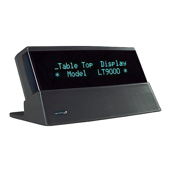
Monitor Logic Controls LT9000 Specifications
Table-top display (1 page)
Monitor Logic Controls LT9000 User Manual
Lt9000 series table displays 2 by 20 character display (16 pages)
Monitor Logic Controls LE1017 User Manual
17" touch screen monitor (59 pages)
Monitor Logic Controls TD3000 Series User Manual
Table displays 2 by 20 character display (13 pages)
Monitor Logic Controls LD9000 Series Specifications
Single & double side pole displays (1 page)
Monitor Logic Controls TD3000 Specifications
Table-top display (1 page)
Monitor Logic Controls LE1017 Series Specifications
Touch screen monitor (2 pages)
Monitor Logic Controls LT9000 Series Specifications
Table top displays (1 page)
This manual is also suitable for:
Ldx9 series
Ltx9 series
Pdx3000
Ldx9000
Ltx9000
Table of Contents
Print
Rename the bookmark
Delete bookmark?
Delete from my manuals?
Login
Sign In
OR
Sign in with Facebook
Sign in with Google
Upload manual
Upload from disk
Upload from URL


Need help?
Do you have a question about the PDX3 Series and is the answer not in the manual?
Questions and answers