Table of Contents
Advertisement
Quick Links
Advertisement
Table of Contents

Related Manuals for Logic Controls LE1015


Summary of Contents for Logic Controls LE1015
- Page 1 LE1015 True-flat LCD Touch Monitor USER MANUAL...
-
Page 2: Table Of Contents
Table of Contents Introduction ..................2 Safety Information ..................2 Precaution ....................... 2 Electromagnetic compatibility statement ..........3 2 Overview ....................4 Package Contents ................... 4 Features ......................4 3 Hardware Installation ................5 Connections ....................5 Screw Specification for VESA Plate Stand or Wall Mount ......6 Magnetic Stripe Reader Module Installation (Optional) ...... -
Page 3: Introduction
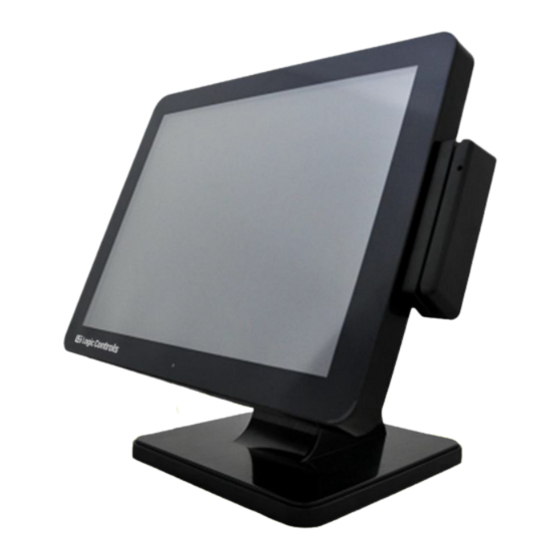
1 Introduction The Bematech LE1015 true-flat TFT 15" color LCD touch monitor is designed and manufactured to meet the requirements of retail and restaurant operations with their POS system. The highly rugged touch monitor includes a solid base with extra wide hinge for maximum stability. -
Page 4: Electromagnetic Compatibility Statement
This product is in conformity with the protection requirements of EU Council Directive 89/336/EEC on the approximation of the laws of the Member States relating to electromagnetic compatibility. Bematech / Logic Controls cannot accept responsibility for any failure to satisfy the protection requirements resulting from a non-recommended modification of the product. -
Page 5: Overview
2 Overview 2.1 Package Contents 1. LE1015 LCD Touch Monitor 2. Power cord 3. VGA cable 4. Audio cable 6. USB cable 5. User manual 7. Driver CD 2.2 Features True-flat, bezel-free design Durable and sturdy base Support integrated MSR and 2nd display ... -
Page 6: Hardware Installation
Hardware Installation 3.1 Connections 1. Connect VGA cable from monitor to computer VGA port 2. Connect USB cable to computer USB port 3. Connect power cord to touch monitor 4. Plug power cord to wall AC power outlet Connectors: AC in: AC power input VGA port: D-Sub 15 pin VGA video input Audio in: Stereo phone jack audio input Touch interface: USB touch input... -
Page 7: Screw Specification For Vesa Plate Stand Or Wall Mount
3.2 Screw Specification for VESA Plate Stand or Wall Mount (B)+5mm ≦ Screw Length (A) ≦ (B)+6mm Mechanical Screw Φ 4 mm Caution: Please follow the Screw Specification in diagram for assembling VESA plate stand or Wall mounts plate into monitor back cover. Otherwise, it may cause mechanical damage. -
Page 8: Magnetic Stripe Reader Module Installation (Optional)
3.3 Magnetic Stripe Reader Module Installation (Optional) 1. Remove the MSR mount cover from the monitor. 2. Insert the MSR module into the MSR USB port on the monitor. 3. Make sure the MSR module is properly inserted and then install the 2 screws to secure it. -
Page 9: Second Display Installation (Optional)
3.4 Second Display Installation (Optional) 1. Connect USB cable to second display and Install VESA bracket set to the second display with 4x M4 screws. 2. Remove the display mount cover from the monitor. - Page 10 3. Mount the second display set to the touch monitor and install screws to secure. Plug USB cable into monitor USB port. USB port...
-
Page 11: Setup And Driver Installation
Setup and Driver Installation 4.1 Control Buttons There are 5 keys for user to set up the monitor. The following describes functions of these Keys. Power Turn the LCD power on and off. When the power is on, the LED is green, When in standby, LED is orange. -
Page 12: On-Screen Display Menu
4.2 On-Screen Display Menu Brightness Adjust brightness of the display Contrast Adjust contrast between light and dark area Auto Adjust Adjust display to optimum settings automatically H Position Adjust horizontal position of the display image V Position Adjust vertical position of display image Clock Adjust frequency of the PLL Phase... -
Page 13: Touch Screen Driver Installation
4.3 Touch screen driver installation 4.3.1 Navigate to the CDROM or installation program directory to find the file setup.exe. Double-click on “setup.exe” to start installation. 4.3.2 When installation starts, click [Next] to proceed to the next step. 4.3.3 Installation in progress 4.3.4 Uncheck “Install PS/2 interface driver”... - Page 14 4.3.5 Uncheck “install RS232 interface driver” and click [Next] to continue installation. 4.3.6 Select option “NONE”, click [Next] to continue installation. 4.3.7 If there are additional touch monitors connected, please check “Support multi- monitor system”.
- Page 15 4.3.8 Select the destination location to install the touch driver. The default path is “C:\Program Files\eGalaxtouch”. Click [Next] to continue installation. 4.3.9 Select the Program Folder to install the utility. The default is “eGalaxtouch”. Click [Next] to continue installation. 4.3.10 Check the option to create a desktop shortcut icon. Click [Next] to continue.
- Page 16 After install the driver successfully, identify the USB controller is installed as shown below. 4.3.11 Click on "Settings" tab to change the touch function settings as needed.
- Page 17 4.3.12 If necessary, perform 4-point touch calibration and/or 9-point/25-point linearization. 4.3.13 Use Draw Test to check touch accuracy after calibration.
-
Page 18: Troubleshooting
5 Troubleshooting 1) There is no picture on the screen (a) Check if monitor is in power saving mode. Press any key and move the mouse to deactivate the mode. (b) Check signal cable connector pins. If there are bent or missing pins, replace the cable or consult your place of purchase. - Page 19 after changing monitor resolution. (b) Run the touch screen calibration program to do a 4-point calibration and/or 9-point / 25-point linearization. 7) Touch screen does not respond to touch operations Check and make sure that touch screen controller driver is installed properly in the computer and calibrate touch screen before using it.
-
Page 20: Supported Timings
6 Supported Timings Vertical Horizontal Sync Dot Clock Scanning Scanning Polarity or Operating Item Standards Resolution (MHz) Frequency Frequency composite Mode (Hz) (KHz) sync (H/V) 640x480 25.18 59.94 31.47 Analog VESA 640x480 31.50 72.81 37.86 Analog VESA 640x480 31.50 75.00 37.50 Analog VESA... -
Page 21: Specifications
7 Specifications LCD TOUCH PANEL LCD size 15" Display active area 304.1mm × 228.1mm Brightness 250 cd/m typical Response time 12ms typical Contrast ratio 800:1 typical Resolution XGA 1024 x 768 @75Hz (non-interlaced), 16.2M colors Viewing angle (CR10) Horizontal: 160, Vertical: 145, typical Touch screen 5-wire resistive touch panel, USB interface MECHANICAL... - Page 22 LE1015 True-flat Touch Monitor logiccontrols.com...
Need help?
Do you have a question about the LE1015 and is the answer not in the manual?
Questions and answers