Table of Contents
Advertisement
QUESTIONS?
Ask the experts at POSMicro.com.
1.800.241.6264
Live Chat Now
support@POSMicro.com
Monday - Friday 6 AM to 5 PM Pacific Time
1.800.241.6264
Logic Controls LE1000
Manual
More information available at
BULk DISCOUNTS
FREE SHIPPING*
*Free ground shipping to the continental USa on orders over $100.
For Help Call
POSMicro.com
SE HaBLa
ESpañOL
Advertisement
Table of Contents

Related Manuals for Logic Controls LE1000


Summary of Contents for Logic Controls LE1000
- Page 1 For Help Call 1.800.241.6264 Logic Controls LE1000 Manual More information available at POSMicro.com QUESTIONS? BULk DISCOUNTS SE HaBLa Ask the experts at POSMicro.com. ESpañOL FREE SHIPPING* 1.800.241.6264 Live Chat Now support@POSMicro.com Monday - Friday 6 AM to 5 PM Pacific Time...
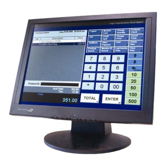
- Page 2 15” Touch Screen Monitor...
-
Page 3: Table Of Contents
Contents Notice...................... 3 Safety Information................. 3 Precaution ....................3 Package Contents ................... 3 Hardware Installation ................4 Input......................4 Control Buttons..................5 OSD (On-Screen Display) Menu Mode............. 6 Screw Specification for VESA Plate Stand or Wall Mount ..... 8 Quick Installation Guide for Touch Panel Driver ........9 Calibration Guide for Touch Panel............ -
Page 4: Notice
Notice ‧ All Information in this manual may change without prior notice. ‧ To ensure safety operation of this product, please read the following menu carefully before using this product. Safety Information ‧ Do not place anything wet on the monitor or the power cord. ‧... -
Page 5: Hardware Installation
Hardware Installation Turn off LCD’s and PC’s power before you set it up. Follow our installation step by step. Input 【1】AC Input : This is for connecting the power cable. 【2】VGA PORT : This can be connected with the D-Sub 15 pin signal cable. 【3】Touch Panel Interface : USB 【4】Audio In : This can be connected to the PC audio-out connector of sound resource. -
Page 6: Control Buttons
Control Buttons There are 5 keys for user to set up the monitor, including "Auto Adjust", "OSD menu", "Power", "Adjust <->", "Adjust <+>". The following descriptions are the introduction of these Keys. Auto Adjust (Function)-- Function Select Button: This button allows you to select the control functions up in the OSD. -
Page 7: Osd (On-Screen Display) Menu Mode
OSD (On-Screen Display) Menu Mode Please adjust your Speaker Volume via your PC computer Speaker Volume control icon. Please note that Sound will continue to play when your monitor is off, to turn off please turn off your PC computer or mute the Speaker Volume control icon. Press the OSD button to access menu, and press Increase / Decrease button for adjustment. -
Page 8: Screw Specification For Vesa Plate Stand Or Wall Mount
Screw Specification for VESA Plate Stand or Wall Mount (Safety Space) (Safety Space) (B)+5mm ≦ Screw Length (A) ≦ (B)+6mm 2. Mechanical Screw Φ 4 mm Caution: Please follow the Screw Specification in diagram while you assembling VESA Plate stand or Wall Mount Plate into monitor back cover. Otherwise, It may cause a mechanical damage. -
Page 9: Quick Installation Guide For Touch Panel Driver
Quick Installation Guide for Touch Panel Driver The Driver supports a lot of operating systems, i.e. Windows 95, Windows 98, Windows ME, Windows NT4, Windows 2000, Windows XP, Windows XP Tablet PC Edition, Windows CE2.12/3.0/.NET, DOS, iMac, RedHat / Mandrake Linux. Follow these steps to install Touch Panel Driver. -
Page 10: Calibration Guide For Touch Panel
Calibration Guide for Touch Panel 4 points calibration 1. It needs calibration before the touchscreen can work accurately. Whenever the user feel the accuracy lost, user can do calibration again to get a more accuracy touch function. 2. Pressing this button, a new window will be popped-up at the location when the touchscreen was mapped to area for this touch system to guide the user do 4 points calibration. - Page 11 symbol in the calibration window until it does not blink to make sure that the utility can gather enough data for computation. In addition, a time line bar is shown in the bottom of the window to indicate time elapsed. If the touchscreen was not touched before the time line bar going to right end, the calibration task will be terminated automatically.
-
Page 12: Troubleshooting
Troubleshooting Make sure that your monitor is properly installed if you have encountered any trouble using this product. There is no picture on the screen. Check: Power saving mode. Press any key and move the mouse to deactivate the mode. 2. - Page 13 VESA 800x600 49.50 75.00 46.88 720x400 28.32 70.09 31.47 1024x768 65.00 60.00 48.36 VESA 1024x768 75.00 70.07 56.48 VESA 1024x768 78.75 75.03 60.02 A = Analog Mode If the input timing is closed to one of the above, generally it can be displayed well by optimum adjusting.
-
Page 14: Specification
Specification Input Signals VGA compatible analog RGB Composite sync supported Compatibility Up to 1024X768@75Hz(Non-interlaced) Connector D-sub 15-pins Audio* Stereo Phone Jack Touch* USB* RS-232* Power A/C Input Power Voltage Built-in universal power supply: 100-240 VAC, Consumption 50/60 Hz Power saving mode Active <... -
Page 15: Limited Warranty Policy
Limited Warranty Policy All LCD monitors feature a three-year-limited warranty with free change in the first year from the date of purchase. If product is determined to be defective, we will repair or replace the product with refurbished or remanufactured parts or components during the warranty period. - Page 16 15” Touch Screen Monitor...
Need help?
Do you have a question about the LE1000 and is the answer not in the manual?
Questions and answers