
Related Manuals for Magnum Energy MagnaSine Hybrid


Summary of Contents for Magnum Energy MagnaSine Hybrid
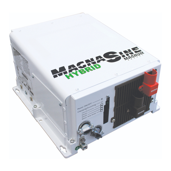
- Page 1 MagnaSine Hybrid – Renewable Energy Series Pure Sine Wave Inverter/Charger MSH-RE Series Owner’s Manual...
- Page 2 Copyright Notice Copyright © 2013 by Magnum Energy, Inc. All rights reserved. Permission to copy, distribute, and/or modify this document is prohibited without express written permission from Magnum Energy, Inc. Document Information Description –...
- Page 3 Overcurrent protection for the battery supply is not provided as an integral part of this inverter. Overcurrent protection of the battery cables must be provided as part of the system installation. Refer to Section 2.4 “DC Wiring” for more information. Page ii © 2013 Magnum Energy, Inc.
- Page 4 Safety Information • Overcurrent protection for the AC output wiring is not provided as an integral part of this inverter. Overcurrent protection of the AC output wiring must be provided as part of the system installation. Refer to Section 2.5 “AC Wiring” for more information. Note: An output breaker is provided on the inverter to provide overcurrent protection to the inverter’s internal wires;...
- Page 5 La protection contre les surintensités des câbles de batterie doivent être fournis dans le cadre de l’installation du système. Reportez-vous à la Section Câblage cc dans le chapitre d’installation pour plus d’informations. Page iv © 2013 Magnum Energy, Inc.
- Page 6 Safety Information • Protection contre les surintensités pour le câblage de sortie AC n’est pas fourni en tant que partie intégrante de cet onduleur. Protection contre les surintensités du câblage de sortie CA doit être fournie dans le cadre de l’installation du système. Reportez-vous à la Section 2.5 Câblage ca dans le chapitre d’installation pour plus d’informations.
-
Page 7: Table Of Contents
Appendix C – Power Consumption and Output Waveforms ....51 Appliance Power Consumption ..............51 Inverter Output Waveforms ................51 Appendix D – Inverter/Charger Terminology ........52 Appendix E – Warranty and Service Information .........54 Limited Warranty ..................54 How to Receive Repair Service ..............55 © 2013 Magnum Energy, Inc. Page vi... - Page 8 Table 3-2, Inverter/Charger Default Values ..............39 Table 3-3, Inverter Compatibility Level ................40 Table 3-4, Remote Compatibility Level ................40 Table 4-1, Basic Inverter Troubleshooting (Remote not available) ........42 Table C-1, Typical Appliance Power Consumption ..............51 Page vii © 2013 Magnum Energy, Inc.
-
Page 9: Introduction
Introduction 1.0 Introduction Congratulations on your purchase of the MagnaSine Hybrid – Renewable Energy (i.e., MSH-RE) inverter/charger from Magnum Energy. The MSH-RE Series is a “hybrid” pure sine wave inverter designed especially for home backup power and renewable energy applications. Powerful, yet simple to use, this inverter/charger will provide you with years of trouble-free performance you have come to expect from Magnum Energy. -
Page 10: How An Inverter/Charger Works
Magnum accessories such as the Advanced Remote Control (ME- ARC), Standard Remote Control (ME-RC), Automatic Generator Start-Networked (ME-AGS-N), and Battery Monitor Kit (ME-BMK) can be used—see Section A-3 “Optional Equipment and Accessories” for more information on these products. Page 2 © 2013 Magnum Energy, Inc. -
Page 11: Features And Benefi Ts
Network Port (green label – RJ11 connection) Remote Port (blue label – RJ11 connection) Battery Temp Sensor Port (yellow label – RJ11 connection) Figure 1-1, Power Switch, Status LED, and Accessory Connection Ports © 2013 Magnum Energy, Inc. Page 3... -
Page 12: Figure 1-2, Electrical Connection Points
Intake Air Vents (and on right side) Positive (+) DC terminal (under cover) Negative (-) AC Entry/ DC terminal Exit (under Connections cover) Mounting Flange Equipment Ground Terminal Figure 1-2, Electrical Connection Points Page 4 © 2013 Magnum Energy, Inc. -
Page 13: Figure 1-3, Left Side Features
60 amps or damage to the relays may occur. Model/Serial Number Label AC Access Cover Exhaust Air Vents (and on right side - rear) CB1 (60A) AC1 Input CB3 (60A) CB2 (60A) AC Output AC2 Input Figure 1-3, Left Side Features © 2013 Magnum Energy, Inc. Page 5... -
Page 14: Installation
If items appear to be missing or damaged, contact your authorized Magnum Energy dealer or Magnum Energy. If at all possible, keep your shipping box to help protect your inverter from damage if it ever needs to be returned for service. Save your proof-of-purchase as a record of your ownership;... -
Page 15: Figure 2-1, Simplifi Ed Installation Diagram
Inverter/ AC1 (GRID) Input Charger Overcurrent Shunt Protection (breaker or fuse/switch) ME-BMK Battery Monitor with shunt (Magnum Accessory) Battery Bank ME-SBC Smart Battery Combiner (Magnum Accessory) Figure 2-1, Simplifi ed Installation Diagram © 2013 Magnum Energy, Inc. Page 7... - Page 16 Away from sensitive electronic equipment – High powered inverters can generate levels of RFI (Radio Frequency Interference). Locate any electronic equipment susceptible to radio frequency and electromagnetic interference as far away from the inverter as possible. Page 8 © 2013 Magnum Energy, Inc.
-
Page 17: Mounting The Inverter
IS MOUNTED IN THIS MP-HOOD POSITION INVERTER HOOD ON TOP ME-CB/ AND EITHER THE MPX-CB ( CONDUIT BOX ON BOTTOM ERIES NCLOSURE MUST BE USED OUNTED TERMINALS TO THE RIGHT Figure 2-2, Approved Mounting Positions © 2013 Magnum Energy, Inc. Page 9... -
Page 18: Figure 2-3, Msh4024Re Dimensions And Side Reference
Installation Figure 2-3, MSH4024RE Dimensions and Side Reference Page 10 © 2013 Magnum Energy, Inc. -
Page 19: Wiring The Inverter - General Requirements
Ground wiring to and from the inverter. 2.3.4 Torque Requirements Torque all AC wiring connections to 32 in lbf (3.6 N-m). Torque DC cable connections from 10 to 12 ft lbf (13.6 to 16.3 N-m). © 2013 Magnum Energy, Inc. Page 11... -
Page 20: Dc Wiring
• Color code the DC cables/wires with colored tape or heat shrink tubing: RED for positive (+); WHITE for negative (-); and GREEN (or bare copper) for DC ground, to avoid polarity problems. Page 12 © 2013 Magnum Energy, Inc. -
Page 21: Figure 2-4, Dc And Battery Temperature Sensor Wiring
DC busbars). Battery Bank’s Equipment Ground Wire Battery Bank’s Negative Cable Battery Bank’s Positive Cable DC System Grounding point [Electrode Conductor (i.e., ground busbar)] Battery Bank Figure 2-4, DC and Battery Temperature Sensor Wiring © 2013 Magnum Energy, Inc. Page 13... -
Page 22: Table 2-1, Recommended Dc Wire/Overcurrent Device For Rated Use
Note – May not allow continuous operation at full rated power as defi ned by the NEC. Page 14 © 2013 Magnum Energy, Inc. -
Page 23: Figure 2-5, Battery Hardware Installation
(with ring lug) 5/16–18 bolt, Kep nut and battery post. 5/8" usable length battery battery cable post (with ring lug) Figure 2-6, Inverter DC Hardware Figure 2-5, Battery Hardware Installation Installation © 2013 Magnum Energy, Inc. Page 15... - Page 24 For compartment or enclosure installations, always vent batteries to the outside. Info: To ensure the best performance from your inverter system, batteries should be of the same size, type, rating, and age. Do not use old or untested batteries. Page 16 © 2013 Magnum Energy, Inc.
-
Page 25: Figure 2-7, Battery Temperature Sensor
3. Connect the RJ11 connector end of the BTS cable to the yellow-labeled BTS port on the inverter (Item 6, Figure 1-1). FRONT VIEW ~2" ~1" (~5.1 cm) (~2.54 cm) ~¾” (~1.9 cm) 0.375" diameter Cable (~.95 cm) ~½” (~1.3 cm) SIDE VIEW Figure 2-7, Battery Temperature Sensor © 2013 Magnum Energy, Inc. Page 17... - Page 26 Attach the red and black terminal covers over the inverter’s DC connectors and secure them in place with the supplied screws. If the batteries are in an enclosure, perform a fi nal check of the connections to the battery terminals, then close and secure the battery enclosure. Page 18 © 2013 Magnum Energy, Inc.
-
Page 27: Ac Wiring
CAUTION: The inverter’s internal AC transfer relay contacts are rated for 60 amps, the pass-thru current for relay contact must be no greater than 60 amps or damage to this relay may occur. © 2013 Magnum Energy, Inc. Page 19... -
Page 28: Figure 2-8, Ac Terminal Block
Installation 2.5.3 Recommended GFCI (Ground Fault Circuit Interruption) Outlets In compliance with UL standards, Magnum Energy has tested the following GFCIs and fi nd that they function properly when connected to the inverter’s AC output: • Leviton Smart Lock #8899-A •... - Page 29 32 in lbf (3.6 N-m), and the AC ground terminal is torqued to a maximum tightening torque of 45 in lbf (5.1 N-m). 4. Replace the AC wiring access cover and the covers on the main electrical/distribution panel. © 2013 Magnum Energy, Inc. Page 21...
-
Page 30: Figure 2-9, Ac Wiring
AC output. Sub-Panel and Outlets (Inverter AC Loads) A maximum 60-amp single-pole breaker is required on the inverter’s AC input. Main Panel Generator (Utility ≤ 60A) Figure 2-9, AC Wiring Page 22 © 2013 Magnum Energy, Inc. -
Page 31: Grounding Inverters
Neutral Negative AC Ground DC Ground Grounding System GEC-AC GEC-DC Grounding Electrode Grounding Electrode Grounding Electrode (AC side dedicated) (AC and DC sides shared) (DC side dedicated) Figure 2-10, Grounding System for MSH-RE © 2013 Magnum Energy, Inc. Page 23... -
Page 32: Figure 2-11, Multiple Connections To Dc Ground Rod (Method 1)
AC Ground DC Ground Grounding EGC - AC EGC - DC System GEC-DC GEC-AC Grounding Electrode Grounding Electrode (AC side dedicated) (DC side dedicated) Figure 2-11, Multiple Connections to DC Ground Rod (Method 1) Page 24 © 2013 Magnum Energy, Inc. -
Page 33: Figure 2-12, Multiple Connections To Dc Ground Rod (Method 2)
Neutral Negative Neutral Negative AC Ground DC Ground EGC - AC EGC - DC Grounding GEC-AC System GEC-DC Grounding Electrode (DC side dedicated) Figure 2-13, Single Connection to DC Ground Rod (Method 3) © 2013 Magnum Energy, Inc. Page 25... -
Page 34: Table 2-4, Equipment Grounding Conductor Sizing
#12 AWG (3.3 mm 30 - 60 amps #10 AWG (5.3 mm 100 amps #8 AWG (8.4 mm 200 amps #6 AWG (13.3 mm 300 amps #4 AWG (21.1 mm 400 amps #3 AWG (26.7 mm Page 26 © 2013 Magnum Energy, Inc. -
Page 35: Inverter Notifi Cation Requirements
Buildings, facilities, or structures with both utility service and a photovoltaic system must have a permanent plaque or directory providing the location of the service disconnecting means and the photovoltaic system disconnecting means if they are not in the same location. © 2013 Magnum Energy, Inc. Page 27... -
Page 36: Final Inspection
4. Replace the covers on the main electrical/distribution panel. 5. Replace the chassis access cover. 6. Verify the inverter’s front panel switch is in the “OFF” position. Info: If required by code, have the installation inspected by an electrical inspector. Page 28 © 2013 Magnum Energy, Inc. -
Page 37: Functional Test
Troubleshooting section in this manual. AC Terminal Block CB3 (60A) CB2 (60A) CB1 (60A) AC2 INPUT AC1 INPUT AC OUTPUT AC Output 120VAC (+/- 5%) Neutral to Ground < 0.5VAC Figure 2-16, AC Voltage Checks © 2013 Magnum Energy, Inc. Page 29... -
Page 38: Operation
GEN IN (AC2) HOT OUT (60A) (60A) AC2 Hot Transfer Relay NEUTRAL OUT NEUTRAL IN AC GROUNDS Output Relay DC NEGATIVE DC POSITIVE FET Bridge Power Transformer Figure 3-1, Power Flow – Inverter Mode Page 30 © 2013 Magnum Energy, Inc. -
Page 39: Standby Mode
HOT OUT (60A) (60A) AC2 Hot Transfer Relay NEUTRAL OUT NEUTRAL IN AC GROUNDS Output Relay DC NEGATIVE DC POSITIVE FET Bridge Power Transformer Figure 3-3, Power Flow – Standby Mode (GEN Input) © 2013 Magnum Energy, Inc. Page 31... - Page 40 3.2.1 Battery Charging Magnum Energy’s MSH-RE Series is equipped with an active PFC (Power Factor Corrected) and PI (Proportional-Integral) multi-stage battery charger. The PFC feature controls the amount of power used to charge the batteries in order to obtain a power factor as close as possible to 1 (or unity).
-
Page 41: Figure 3-4, Automatic 4-Stage Charging Graph
AC meter will indicate the load support process by displaying negative current fl owing from the batteries to the loads. The input amps AC will also drop during this process, while the load amps AC remains the same. © 2013 Magnum Energy, Inc. Page 33... -
Page 42: Current Flow
AC loads, and also converts this current to charge the battery. AC Current MSH Inverter DC Current (Grid/Gen) (Battery) -20A +10A AC Loads (Small) +10A Figure 3-6, MSH Current Flow – Charging and AC Pass-thru Page 34 © 2013 Magnum Energy, Inc. -
Page 43: Figure 3-7, Msh Current Flow - Charger Back-Off
MSH converts any excess current from the battery to power the AC loads and reduce the current from the grid/generator. AC Current MSH Inverter DC Current (Grid/Gen) (Battery) -10A -20A AC Loads (Large) +30A Figure 3-9, MSH Current Flow – Load Support VDC © 2013 Magnum Energy, Inc. Page 35... -
Page 44: Transfer Time
BTS +0.6V connected 0.15 +0.3V No Change -0.15 -0.3V -0.3 -0.6V -0.45 -0.9V -0.6 -1.2V -0.75 -1.5V 104F 113F 122F Temperature reading from BTS Figure 3-10, BTS Temperature to Charge Voltage Change Page 36 © 2013 Magnum Energy, Inc. -
Page 45: Protection Circuitry Operation
Inverter battery turn ON/OFF Levels MSH4024RE HBCO >33.8 VDC HBCI 33.2 VDC LBCI 25.0 VDC LBCO* 20.0 VDC (1 minute delay) (18.0 - 24.4 VDC) LBCO (immediate) 17.0 VDC *adjustable with remote control © 2013 Magnum Energy, Inc. Page 37... -
Page 46: Inverter Startup
AC power that is connected to the inverter’s input is passing through the inverter and is powering the AC loads connected to the inverter’s output). Power ON/OFF pushbutton switch Charging/Inverting Status LED indicator Figure 3-11, Power Switch and Status Indicator Page 38 © 2013 Magnum Energy, Inc. -
Page 47: Factory Default Values
20 VDC (one minute delay) 17 VDC (no delay) Absorption Time 600 Amp Hours (Absorb Time = 120 minutes) Battery Type Flooded – Liquid Lead Acid Charge Rate 100% VAC Dropout 80 VAC © 2013 Magnum Energy, Inc. Page 39... -
Page 48: Inverter Fan Operation
Required’ on the remote compatibility matrix on our website, then your inverter can support the device setting/feature you want. If your inverter does not have the required compatibility level for a feature/setting you want, contact Magnum Energy about a software upgrade. 3.10.1 Remote Compatibility... -
Page 49: Maintenance And Troubleshooting
WARNING: If an automatic generator start device were to start and run the generator for an extended period of time in a confi ned area, a potentially fatal level of CO (carbon monoxide) could accumulate. © 2013 Magnum Energy, Inc. Page 41... -
Page 50: Troubleshooting
This is normal; see Section 3.5 (Battery Temperature DC charge voltage is (BTS) is installed, the DC voltage will Sensor Operation) for more information. higher or lower than increase or decrease depending on the expected. temperature around the BTS. Page 42 © 2013 Magnum Energy, Inc. -
Page 51: Performing An Inverter Reset
Info: If DC disconnects are not used, there may be a momentary spark when the positive battery cable is connected to the inverter’s terminal. This is normal and indicates that the inverter’s internal capacitors are being charged. © 2013 Magnum Energy, Inc. Page 43... -
Page 52: Appendix A - Specifi Cations And Optional Equipment
Shelf or wall (vents not allowed to face downward unless ME-CB or MMP is installed) Weight Unit: 58 lb (26.3 kg) / Shipping: 60 lb (27.2 kg) Max operating altitude 15,000 ft (4570 m) Specifi cations @ 25°C – Subject to change without notice. Page 44 © 2013 Magnum Energy, Inc. -
Page 53: Performance Graphs
25° C. Use this chart to reduce the inverter power draw to avoid an over-temperature shutdown. Temperature in Degrees Celcius Figure A-2, MSH4024RE Inverting Temperature Curve © 2013 Magnum Energy, Inc. Page 45... -
Page 54: Optional Equipment And Accessories
Figure A-3, MSH4024RE Charge Current vs Temperature Curve A-3 Optional Equipment and Accessories The following Magnum Energy components are available for use with the MSH4024RE Series inverter/charger. Some of these items are required depending upon the intended use of the inverter. -
Page 55: Appendix B - Battery Information
AC utility or generator power. Info: For the MSH-RE Series inverter/charger to perform optimally, a minimum battery bank of 200 AH is recommended for moderate loads (<1000W) and greater than 400 AH for heavy loads (≥1000W). © 2013 Magnum Energy, Inc. Page 47... -
Page 56: Battery Bank Sizing Worksheet
AC source for the calculated load, the Total Amp- Hours should be multiplied by 1.2 to factor in an average 80% inverter effi ciency. Page 48 © 2013 Magnum Energy, Inc. -
Page 57: Battery Wiring Confi Gurations
= 200 AH @ 12 VDC 200 AH @ 6 VDC (200 AH) (200 AH) add voltage add capacity add voltage and in series in parallel capacity together Figure B-3, Series-Parallel Battery Wiring © 2013 Magnum Energy, Inc. Page 49... -
Page 58: Figure B-4, Battery Bank Wiring Examples (24-Volt)
24-volt battery bank (two strings of four 6-volt batteries wired in series and connected in parallel) 24-volt battery bank (two strings of four 6-volt batteries wired in series and connected in parallel) Figure B-4, Battery Bank Wiring Examples (24-volt) Page 50 © 2013 Magnum Energy, Inc. -
Page 59: Appendix C - Power Consumption And Output Waveforms
It rises and falls smoothly with time. The grid puts out a sine waveform. Figure C-1, AC Waveforms Any plug-in AC equipment will operate from a sine wave inverter. © 2013 Magnum Energy, Inc. Page 51... -
Page 60: Appendix D - Inverter/Charger Terminology
Appendix D – Inverter/Charger Terminology Appendix D – Inverter/Charger Terminology The following is a glossary of terms with which you may not be familiar. They appear in the various descriptions of inverter and battery charger operation. Absorption Stage – In this second stage of three stage charging, the batteries are held at a constant voltage (the absorb voltage setting) and the battery is charged to its maximum capacity. - Page 61 Battery Temperature Sensor (BTS) automatically re-scales charge-voltage settings to compensate for ambient temperatures. Voltage – The pressure that causes electrical fl ow in a circuit. Watts – Measure of power output or utilization. Watts = Volts x Amps. © 2013 Magnum Energy, Inc. Page 53...
-
Page 62: Appendix E - Warranty And Service Information
Magnum Energy’s limit of liability under this warranty shall be the actual cash value of the product at the time the original purchaser returns the product for repair, determined by the price paid by the original purchaser. Magnum Energy shall not be liable for any other losses or damages. -
Page 63: How To Receive Repair Service
Appendix E – Warranty & Service Information How to Receive Repair Service If your product requires warranty service or repair, contact either: • An Authorized Service Center, which are listed on the Magnum Energy website at http://www.magnumenergy.com/Service/ServiceCenters-US.htm; or • Magnum Energy, Inc. at: Telephone: 425-353-8833 Fax: 425-353-8390 Email: warranty@magnumenergy.com... - Page 64 Magnum Energy, Inc. 2211 West Casino Rd. Everett, WA 98204 Phone: 425-353-8833 Fax: 425-353-8390 Web: www.magnumenergy.com MSH-RE Series Owner’s Manual (PN: 64-0059 Rev A)
Need help?
Do you have a question about the MagnaSine Hybrid and is the answer not in the manual?
Questions and answers