Table of Contents
Advertisement
Quick Links
Advertisement
Table of Contents

Subscribe to Our Youtube Channel
Related Manuals for ETAS ES650.1


Summary of Contents for ETAS ES650.1
- Page 1 ETAS ES650.1 A/D and Thermo Module User Guide...
- Page 2 The data in this document may not be altered or amended without special noti- fication from ETAS GmbH. ETAS GmbH undertakes no further obligation in relation to this document. The software described in it can only be used if the customer is in possession of a general license agreement or single license.
-
Page 3: Table Of Contents
ES650.1 A/D and Thermo Module ........ - Page 4 Ethernet Cable/Power Supply Cable ........37 6.3.1 Y-Cable (ES650.1 in Stand-alone Mode) ......37 6.3.2 Connecting Cables to the ES600.1 .
-
Page 5: About This Document
Presentation of Instructions The target to be achieved is defined in the heading. The necessary steps for his are in a step-by-step guide: Target definition 1. Step 1 2. Step 2 3. Step 3 > Result ES650.1 - User Guide... -
Page 6: Typographical Conventions
(see chapter 7 on page 40). Additional cables and adapters can be obtained separately from ETAS. A list of available accessories and their order designation is located in chapter “Acces- sories” on page 40 of this manual or in the ETAS product catalog. -
Page 7: Basic Safety Notices
Intended use........... 7 General safety information Please observe the Product Safety Notices ("ETAS Safety Notice") and the fol- lowing safety notices to avoid health issues or damage to the device. - Page 8 The lab power supply must be approved for an operating altitude of 5000 m and for an ambient temperature of up to 70 °C. • In regular operation of the modules as well as very long standby opera- tion, a discharge of the vehicle battery is possible. ES650.1 - User Guide...
- Page 9 • Adhere to the maximum permissible cable lengths! • Do not use any damaged cables! Cables may be repaired only by ETAS! • Never apply force to insert a plug into a socket. Ensure that there is no contamination in and on the connection, that the plug fits the socket, and that you correctly aligned the plugs with the connection.
- Page 10 Do not transport the modules at the cable of the module or any other cables. Maintenance The product is maintenance-free. Repair If an ETAS hardware product should require a repair, return the product to ETAS. Cleaning the module housing • Use a dry or lightly moistened, soft, lint-free cloth for cleaning the module housing.
- Page 11 Install the modules only at locations with the same electrical potential or iso- late the modules from the installation location. Cabling For detailed information about cabling, see the User's Guide of the module. ES650.1 - User Guide...
-
Page 12: Hardware Description
ES600 Measurement Modules ........12 • ES650.1 A/D and Thermo Module ....... 13 •... -
Page 13: Es650.1 A/D And Thermo Module
ETAS Hardware Description “awakened” from its power-saving standby mode and is ready for operation. When it no longer receives any more link signals, the ES650.1 switches back into standby mode automatically after a delay. NOTE The ES650.1 only switches from the power-saving standby mode to opera- tion mode when it receives link pulses via the Ethernet interface. -
Page 14: Features
Fig. 3-2 ES650.1 A/D and Thermo Module back panel 3.2.2 Features Overview of the major features of the ES650.1: • Eight galvanically isolated measurement channels for analog voltages • Two measuring ranges of ±10 V DC and ±60 V DC •... -
Page 15: Package Contents
Before using your ES650.1, check that the unit has been delivered with all required parts and cables. Housing The ES650.1 uses a housing with connections on the front and the rear side of the device. The robust metal housing of the ES650.1 is equipped with non-slip plastic feet. -
Page 16: Ports And Indicators
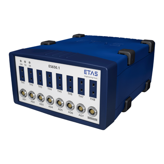
ETAS Hardware Description Ports and Indicators The ES650.1 has three indicators (LEDs), sixteen ports for sensors and trans- ducers, one combined Ethernet/power supply port, and one port for an external display. 3.5.1 Front Side Fig. 3-3 ES650.1 Front panel Ports The eight ports TH1 to TH8 for the thermocouples are located in the top termi- nal row on the front panel. -
Page 17: Indicators
ETAS Hardware Description 3.5.2 Indicators The three indicators (LEDs) are located in the top left corner on the front panel. They indicate the following operational states of the ES650.1: Indicator Indication Operational State green The unit is powered on. green, blinking The unit is in standby mode. -
Page 18: Rear Side
The port for an external display is located on the back panel. The current firm- ware version does not yet support this external display; however, the port has been built in to provide for future use. ES650.1 - User Guide... -
Page 19: Maximum Input And Common-Mode Voltages
) = 2 U = 60 V CMxy CMyz 10 V + 5 V + 10 V + 15 V + max(U ) = 60 V CMyz max(U ) = 60 V - 40 V = 20 V CMyz ES650.1 - User Guide... -
Page 20: Measurement Accuracy
T = 0.29 K + 0.00 K + 0.00 K + 1 K + 0.00 K T = 1.29 K In this example the maximum total inaccuracy is determined by the inaccuracy of the cold junction compensation. ES650.1 - User Guide... - Page 21 Determinating the Internal Resistance of a Thermocouple The internal resistance of a thermocouple can be measured with an ohmmeter. The error appearing from the enclosed thermo voltage is negligible. ES650.1 - User Guide...
-
Page 22: Getting Started
4.1.2 Fastening the module onto a carrier system The ES650.1 has a robust metal housing equipped with non-slip plastic feet. The module can easily be screwed onto a support system for fastening in the vehicle or lab. The screw threads for fastening the module are already in the housing and easily accessible. -
Page 23: Connecting Several Modules Mechanically
4.1.3 Connecting several modules mechanically Because of the use of ETAS system enclosures, the ES650.1 can also be com- bined with modules of the ETAS compact series (ES59x, ES6xx, ES910). They can simply be combined into larger blocks by using the supplied T-connectors. -
Page 24: Cabling
This section describes how to connect the sensors, transducers and the host PC to your ES650.1 A/D and Thermo Module. For information on how to con- nect several ES6xx series devices to a host PC, see the ES600 User Manual. - Page 25 To use the ES650.1 with additional ES6xx series devices: 1. To use your ES650.1 with several ES6xx series devices, con- nect the 7-29 V / HOST port of the ES650.1 to an ES600 via a CBE130 or a CBE140 cable that can be ordered separately. Be sure to observe the color coding of the connectors.
-
Page 26: Configuration
The ES650.1 has no switches or controls. The configuration is exclusively per- formed by software within INCA. Write down which signal you have connected to which input of the ES650.1. Use the configuration sheet in Section “Configuration” on page 43 for this pur- pose. -
Page 27: Technical Data
Marking for CE conformity (Chapter 5.3 on page 29) Marking for UKCA conformity (Chapter 5.4 on page 29) Marking for KCC conformity (Chapter 5.5 on page 29) Labeling for RoHS (China), see chapter on page 29 ES650.1 - User Guide... -
Page 28: Fulfilled Standards And Norms
Degree of pollution NOTE The module is suited for use in interiors, in the passenger compartment or in the luggage compartment of vehicles. The ES650.1 is not suited for installa- tion in the engine compartment and similar environments. 5.1.4 Maintenance the Product Do not open or change the module! Works on the module housing may be exe- cuted only by qualified technical personnel. -
Page 29: Rohs Conformity
China RoHS marking affixed to the product or its packaging. CE conformity With the CE mark attached to the product or its packaging, ETAS confirms that the product corresponds to the product-specific, applicable directives of the European Union. -
Page 30: Use Of Open Source Software
System Requirements 5.8.1 Hardware Operating the ES650.1 module requires a DC voltage supply of 7 V to 29 V. PC with one Ethernet interface A PC with one open Ethernet interface (10 Mbit/s, full duplex) with RJ-45 con- nection is required. Ethernet interfaces that are implemented with an additional network card in the PC must feature a 32-bit data bus. -
Page 31: Software
INCA V4.0 and higher is required for the configuration of the ES650.1 and for control and data acquisition. INCA V5.2.1 and HSP4.1 are required for use of B- , E-, R-, S- and T-type thermocouples. It is not possible to run the ES650.1 with earlier INCA versions. -
Page 32: Electrical Data
2 M || 1 nF im ±60 V measuring range Maximum inaccuracy 0.05% + 2 mV in ±10 V measuring range; 0,05% + 12 mV in ±60 V measuring range Maximum temperature drift 10 ppm / K ES650.1 - User Guide... -
Page 33: Thermocouple Inputs
T Maximum temperature drift of cold ±0.008 K/K junction compensation T Maximum allowed input voltage 32 V DC Reference temperature T for T , T and T is 25 °C (equivalent to 298.15 K). ES650.1 - User Guide... -
Page 34: Pin Assignment
5.10 Pin Assignment This section specifies the pin assignment of the electrical connectors of the ES650.1. All connectors are shown as seen on the front or back panel of the ES650.1. NOTE All shieldings are at case potential. The housings are galvanically isolated from all inputs and outputs. -
Page 35: Ethernet Interface, Power Supply
External Display Signal Meaning STBY5V Supply voltage, standby, 5 V Receive data Send data DTRE Ready to receive Ground Ground VCC5 Supply voltage, 5 V NOTE The current firmware version does not yet support the external display. ES650.1 - User Guide... -
Page 36: Cables And Accessories
Ethernet Cable/Power Supply Cable ......37 NOTE Only use ETAS cables at the interfaces of the ES650.1. The maximum admis- sible cable lengths must be adhered to. -
Page 37: Ethernet Cable/Power Supply Cable
Connect the power cable only with a suitable vehicle battery or with a suitable lab power supply! The connection to power outlets is not allowed! To prevent an inadvertent insertion in power outlets, ETAS recommends to equip the power cables with safety banana plugs CBEP1105 or CBEP1205 in areas with power outlets. -
Page 38: Connecting Cables To The Es600.1
CBE130 (Straight Cable) Side A Side B Fig. 6-8 CBE130-x Cable Product Length Order Number CBE130-0m45 0.45 m F 00K 102 748 CBE130-1 F 00K 102 588 CBE130-3 F 00K 102 587 CBE130-8 F 00K 102 586 ES650.1 - User Guide... -
Page 39: Fig. 6-9 Cbe140-0M45 Cable
CBE140 (Angled Cable) Side A Side B Fig. 6-9 CBE140-0m45 Cable Product Length Order Number CBE140-0m45 0.45 m F 00K 104 153 CBE140-1 F 00K 104 154 CBE140-3 F 00K 104 155 CBE140-8 F 00K 104 156 ES650.1 - User Guide... -
Page 40: Ordering Information
ETAS Ordering Information Ordering Information ES650.1 Order Name Short Name Order Number ES650.1 Module, Cable CBEP110-2, ES650.1 F 00K 102 751 4 T-Brackets for ES600 Housing ES650.1 Module, ES650.1-SCB F 00K 104 056 4 T-Brackets for ES600 Housing Accessories Combined Ethernet Cable and Power Supply Cord (Y-Cable) -
Page 41: Calibration
T-bracket for housing ES600_H_TB F-00K-001-925 Unit feet ES600_H_F F-00K-001-924 7.2.1 Calibration NOTICE ETAS recommends a calibration interval of 12 months. 7.2.1.1 Factory calibration Factory calibration service • Verification of measurement accuracy • Issue a standard-compliant calibration certificate Order name Short name... - Page 42 Issue of internationally recognized, ISO/IEC 17025 compliant calibration certificates for "pre-adjustment" and "post-adjustment" Order name Short name Order number DAkkS adjustment service for ES650 DAkkS_A_ES650 F-00K-111-156 1. Accreditation by Deutsche Akkreditierungsstelle (DAkkS) 2. Supervision of the calibration certificate by DAkkS ES650.1 - User Guide...
-
Page 43: Configuration
Configuration The following form can be used to note the individual connections to your ES650.1. These data will assist you in configuring your ES650.1 in INCA later Copy this page and fill out the tables when cabling your measuring system. -
Page 44: Contact Information
Germany Internet: www.etas.com ETAS Subsidiaries and Technical Support For details of your local sales office as well as your local technical support team and product hotlines, take a look at the ETAS website: ETAS subsidiaries Internet: www.etas.com/en/contact.php ETAS technical support Internet: www.etas.com/en/hotlines.php... -
Page 45: Figures
ES650.1 A/D and Thermo Module ........ -
Page 46: Index
Power supply cord ....40 ES600_H_F ......41 Product ES650.1 - User Guide... - Page 47 WEEE take-back System ... . .30 Y-cable ......40 ES650.1 - User Guide...
Need help?
Do you have a question about the ES650.1 and is the answer not in the manual?
Questions and answers