Table of Contents
Advertisement
Quick Links
Advertisement
Table of Contents

Related Manuals for Saluki CSA Series


Summary of Contents for Saluki CSA Series
- Page 1 CSA Series Signal Analyzer User Manual Saluki Technology Inc.
- Page 2 1 × USB Cable (USB3.1, Type-C to USB-A) 1 × U Disk (Software & User Manual) 1 × Certificate of Calibration 1 × Carrying Case Options of the CSA series signal analyzer: Module No. Item Description...
- Page 3 Saluki. Saluki Tech owns the copyright of this document which should not be modified or tampered by any organization or individual, or reproduced or transmitted for the purpose of making profit without its prior permission, otherwise Saluki will reserve the right to investigate and affix legal liability of infringement.
- Page 4 Tel: 886. 909 602 109 Email: sales@salukitec.com www.salukitec.com Contact Service Tel: 886. 909 602 109 Website: www.salukitec.com Email: sales@salukitec.com Address: No. 367 Fuxing N Road, Taipei 105, Taiwan (R.O.C.) Safety Notice The instrument casing can prevent users from touching the internal parts of the instrument, but the casing is not waterproof.
-
Page 5: Table Of Contents
Tel: 886. 909 602 109 Email: sales@salukitec.com www.salukitec.com Contents 1 Overview................................... 6 2 Start To Use................................7 2.1 Software Installation............................7 2.2 Hardware Connection............................8 2.3 Confirmation of Connection Status........................8 2.4 Front Panel Description........................... 10 2.5 Rear Panel Description............................10 3 Software Function Description..........................12 4 Remote Control............................... -
Page 6: Overview
1 Overview The CSA series signal analyzer meets your signal observation and analysis needs in the 100 kHz to maximum 26.5 GHz frequency range. You can use it to measure and observe a variety of signal characteristics for manufacturing, R&D, repair service, and education. -
Page 7: Start To Use
2.1 Software Installation The CSA series signal analyzer itself do not have a display interface, and the parameter settings and display function are provided by the A1000A software running on PC. The software that controls this product needs to be installed on the PC before use. You can download or run the installer on the CD-ROM from the Saluki website. -
Page 8: Hardware Connection
Tel: 886. 909 602 109 Email: sales@salukitec.com www.salukitec.com 2.2 Hardware Connection Insert USB cable’s Type-C plug into (1) and insert the AC/DC power adapter’s DC plug into (3) on the rear panel. If the power is OK, the indicator button (2) LED light will light up for 3 seconds. then goes out, indicating the device is in standby mode. The specification of the power adapter is 220VAC-12VDC/10A. - Page 9 Tel: 886. 909 602 109 Email: sales@salukitec.com www.salukitec.com Fig. 4 Check whether CSA2026 is correctly identified in “Device Manager” The CSA2026 has a 32GB built in Flash memory to store the copy of the CSA software A1000A. Users can run this copy directly without installing the software(For Windows10 and later versions).
-
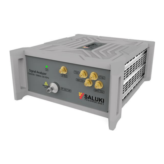
Page 10: Front Panel Description
Tel: 886. 909 602 109 Email: sales@salukitec.com www.salukitec.com Fig. 6 Boot screen (left). Work mode interface(right) 2.4 Front Panel Description The front panel is shown in Fig. 7. The function of each element is described below: Fig. 7 Elements in front panel 1. - Page 11 Tel: 886. 909 602 109 Email: sales@salukitec.com www.salukitec.com Fig. 8 Elements in rear panel 1. USB socket: USB3.0, Type-C interface. 2. Power off button: Long press of the button for powers off, which is used to reduce power consumption after closing the software.
-
Page 12: Software Function Description
Tel: 886. 909 602 109 Email: sales@salukitec.com www.salukitec.com 3 Software Function Description The software operation is almost the same as the traditional desktop spectrum analyzers. The function items are shown in Fig. 9. The functions of each item are described as follows: Fig. - Page 13 Tel: 886. 909 602 109 Email: sales@salukitec.com www.salukitec.com Fig. 10 Function panel popup 3. Menu The menu panel co-operate with function panel (Fig. 10) to complete the measurement settings. Click menu items to make a selection, or go to the next menu level. If the menu item requires numeric input, a soft keyboard will automatically pop up for enter digits.
- Page 14 The device’s working status is displayed here, including system prompts and error messages. Please pay special attention to the system information displayed here when you are using the CSA series signal analyzer, because errors may lead to wrong measurement results (such as amplitude is incorrect when there’s “ADC Overload” warning).
-
Page 15: Remote Control
4 Remote Control CSA series signal analyzer supports remote control via SCPI commands. This chapter explains how to control the product remotely via SCPI. For more detailed SCPI command set details, please refer to "Programming Manual". The remote control host controls the signal analyzer via communicating with the A1000A software. For the hardware connection method, see Fig.
Need help?
Do you have a question about the CSA Series and is the answer not in the manual?
Questions and answers