Table of Contents
Advertisement
Quick Links
Advertisement
Table of Contents

Related Manuals for Saluki S3302 Series


Summary of Contents for Saluki S3302 Series
- Page 1 S3302 Series Spectrum Analyzer Quick Start Guide Saluki Technology Inc.
- Page 2 Saluki. Saluki Tech owns the copyright of this document which should not be modified or tampered by any organization or individual, or reproduced or transmitted for the purpose of making profit without its prior permission, otherwise Saluki will reserve the right to investigate and affix legal liability of infringement.
- Page 3 Tel: 886.909 602 109 Email: sales@salukitec.com www.salukitec.com A “CAUTION” sign provides prompt on important information but not dangerous CAUTION situations. It reminds the user to pay attention to a certain operation process, operation method or the similar. Any violation against the indicated rules or incorrect operation may lead to instrument damage or loss of important data.
-
Page 4: Table Of Contents
Tel: 886.909 602 109 Email: sales@salukitec.com www.salukitec.com CONTENTS Chapter 1 Manual Overview............................5 Chapter 2 Ready for Use..............................6 2.1 Preparation before Operation...........................6 2.1.1 Environmental requirements.........................6 2.1.2 Power supply requirements..........................6 2.1.3 Electrostatic discharge (ESD) protection......................7 2.2 Description of Start for Use.............................8 2.3 Front Panel Overview.............................. - Page 5 Tel: 886.909 602 109 Email: sales@salukitec.com www.salukitec.com 3.3.2 Reduce resolution bandwidth to measure small signals................20 3.3.3 Measuring small signals by using average detection and increasing sweep time........21 3.3.4 Measuring small signals by using video average..................22 3.4 How to Identify Signal with Closely Spaced Frequency..................23 3.4.1 Description of resolution bandwidth......................
-
Page 6: Chapter 1 Manual Overview
Chapter 1 Manual Overview This manual describes the structure and use of the S3302 series spectrum analyzer (hereinafter referred to as S3302 or the spectrum analyzer) in an all-around and three- dimensional manner from aspects of instrument panel, power supply, start to use, typical applications and after-sales help. By reading this Manual, you will have an overall understanding of S3302 and quickly master the basic operations of this device in a systematic manner. -
Page 7: Chapter 2 Ready For Use
2.1.1 Environmental requirements To ensure long service life and effective and accurate measurement of the S3302 series instrument, test it under the following environmental conditions: 1. Temperature range: Storage temperature range: -40℃... -
Page 8: Electrostatic Discharge (Esd) Protection
Tel: 886.909 602 109 Email: sales@salukitec.com www.salukitec.com 1. AC power supply and power supply with adapter The accompanying AC-DC adapter must be used for AC power supply. The input power supply of the adapter is 100~240V, 50/60Hz AC. When transported and carried in a backpack, please do not connect the AC-DC adapter to the device to avoided overheating. -
Page 9: Description Of Start For Use
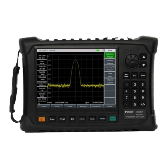
30-minute warming period is recommended before measurement.. 2.3 Front Panel Overview The front panel of the S3302 series spectrum analyzer is as shown in Fig. 2.1. Fig.2.1 Front panel of S3302 series spectrum analyzer 2.3.1 Power key and indicator Power key and the indicator are located at the lower left of the front panel. -
Page 10: Function Key Zone
Tel: 886.909 602 109 Email: sales@salukitec.com www.salukitec.com Table 2.2 Description of indicator status Instrument Indicator status Physical status of the Spectrum Analyzer status battery installed, power not connected. battery not installed, power not connected. a) battery not installed, power connected. Power off Yellow normally on b) battery installed and full, power connected. -
Page 11: Loudspeaker
of the parameters to optimum values. 2.3.6 Loudspeaker The S3302 series spectrum analyzer is equipped with a speaker. Keep the speaker opening clean so as not to affect sound effects. 2.3.6 Label display area It shows the corresponding model, frequency range, label, and name of the S3302 series spectrum analyzer. -
Page 12: Power Interface
Tel: 886.909 602 109 Email: sales@salukitec.com www.salukitec.com Fig.2.3 Top Panel of S3302 Series Spectrum Analyzer 2.5.1 Power interface The power interface of the device is for powering the device through DC output of AC-DC adapter or through external DC power source. The conductor inside the external power interface is positive and the external conductor is grounded. -
Page 13: Device Symbols
Tel: 886.909 602 109 Email: sales@salukitec.com www.salukitec.com Equipment drive should be installed for connecting the device to PC through USB CAUTION interface for the first time. A-type USB interface: This interface is used for connecting USB peripheral equipment, such as USB storage device, USB power detector. - Page 14 Tel: 886.909 602 109 Email: sales@salukitec.com www.salukitec.com Fig. 2.4 Install or replace the battery...
-
Page 15: Chapter 3 Typical Application
Chapter 3 Typical Application The S3302 series spectrum analyzer provides several working modes, including spectrum analysis, interference analyzer (option), AM-FM-PM analyzer (option), power meter (option) and channel scanner (option). Several intelligent measurement functions are provided for each working mode. This chapter mainly describes basic tests under spectrum analyzer mode. - Page 16 Tel: 886.909 602 109 Email: sales@salukitec.com www.salukitec.com Set the span Press 【Freq】 →[Span]. Please note if the span is shown in the active function area in order to confirm currently activated parameter. To reduce the span to, for example, 10MHz, you can input [1] [0] using the numerical keypad and select the unit as [MHz], or you can use 【...
- Page 17 Tel: 886.909 602 109 Email: sales@salukitec.com www.salukitec.com Fig. 3.3 Activating the Marker Adjust the amplitude parameter Generally, optimal amplitude measurement accuracy can be obtained by putting the signal peak at the reference level position, as shown in Fig. 3.4. Press 【 Ampt 】 →[Ref Level] to set the reference level as the amplitude of the marker.
-
Page 18: How To Improve The Accuracy Of Frequency Measurement
Tel: 886.909 602 109 Email: sales@salukitec.com www.salukitec.com Input the name on the interface and then press [OK] to save. Fig. 3.5 File Saving 3.2 How to Improve the Accuracy of Frequency Measurement This section will take the measurement of external 1GHz signal as an instance to describe how to use the marker count function to improve the frequency reading accuracy for measurement. -
Page 19: How To Measure Small Signals
Tel: 886.909 602 109 Email: sales@salukitec.com www.salukitec.com Fig. 3.6 Improving the Accuracy of Frequency Measurement by Using Marker Function The marker counting function can be only used to measure continuous wave signals or discrete spectrum components that their amplitudes are greater than -50dBm and such amplitudes must be 30dB higher than noise levels. - Page 20 Tel: 886.909 602 109 Email: sales@salukitec.com www.salukitec.com Reset the spectrum analyzer Press 【Preset】key to restart the spectrum analyzer. Set the center frequency, the span, and the reference level Set the frequency of the external signal generator to 300MHz and set the amplitude to -80dBm, and connect the radio frequency output end of the signal generator to the radio frequency input end of the spectrum analyzer.
-
Page 21: Reduce Resolution Bandwidth To Measure Small Signals
Tel: 886.909 602 109 Email: sales@salukitec.com www.salukitec.com Fig. 3.8 Small Signals when pre-amplifier On After finishing the test, please remember to increase the attenuation of the Spectrum CAUTION Analyzer to protect the RF input port of the Spectrum Analyzer. 3.3.2 Reduce resolution bandwidth to measure small signals The resolution bandwidth affects the internal noise base of the Spectrum Analyzer but will not affect the level of measured continuous wave signal. -
Page 22: Measuring Small Signals By Using Average Detection And Increasing Sweep Time
Tel: 886.909 602 109 Email: sales@salukitec.com www.salukitec.com Reduce the resolution bandwidth with the step key 【↓】 As shown in Fig. 3.9, the noise floor reduces and therefore we can see the signal more clearly. Fig. 3.9 Measuring Small Signals by Reducing Resolution Bandwidth As the reduction of resolution bandwidth will increase the sweep time, in the S3302 Spectrum Analyzer, resolution bandwidth 1Hz - 10MHz is realized by step 1-3-10. -
Page 23: Measuring Small Signals By Using Video Average
Tel: 886.909 602 109 Email: sales@salukitec.com www.salukitec.com manually. Increase the sweep time of the spectrum analyzer Press 【Sweep】and [Sweep Time Auto Man] and increase the sweep time with the step key 【↑】 . By increasing the sweep time, there may be more time for averaging data at each trace pixel point. 3.3.4 Measuring small signals by using video average In video average function, digital method is used to average the mean values of current trace point for sweeping and previous same trace position. -
Page 24: How To Identify Signal With Closely Spaced Frequency
Tel: 886.909 602 109 Email: sales@salukitec.com www.salukitec.com Fig. 3.10 Measuring Small Signals by Using Track Average 3.4 How to Identify Signal with Closely Spaced Frequency 3.4.1 Description of resolution bandwidth Signal resolution is determined by the bandwidth of IF filter of the Spectrum Analyzer, i.e. the resolution bandwidth (RBW) When a signal passing through the IF filter, the Spectrum Analyzer uses the signal to sweep the band pass shape of the IF filter. - Page 25 Tel: 886.909 602 109 Email: sales@salukitec.com www.salukitec.com Press 【Preset】key to restart the spectrum analyzer. Set the signal generator Use a T connector to connect the output of two signal generators to the RF input port of the Spectrum Analyzer, as shown in Fig.
- Page 26 Tel: 886.909 602 109 Email: sales@salukitec.com www.salukitec.com Fig. 3.12 Unable to distinguish two signals of same amplitude Fig. 3.13 Distinguishable two signals with same amplitude...
-
Page 27: Chapter 4 Getting Help
You can inspect the S3302 as per the following instructions in the case of any failure in your device. Please contact us if the failure cannot be removed. If the S3302 series can’t be started when the Power key is pressed, check whether the power supply is ... -
Page 28: Repair Methods
Tel: 886.909 602 109 Email: sales@salukitec.com www.salukitec.com Contacts: Service Tel: 886.909 602 109 Website: www.salukitec.com Email: sales@salukitec.com Address: No. 367 Fuxing N Road, Taipei 105, Taiwan (R.O.C.) All instruments supplied by us pass inspection by the Quality and Safety Department of the company, and they are guaranteed for 36 months from the date of delivery and maintained for a long time. -
Page 29: Appendix 1 Technical Specifications
Appendix 1 Technical Specifications The technical indexes of S3302 series spectrum analyzer are subject to strict test when ex-factory. The user can test and verify the device based on the technical indexes in this manual. Main technical indexes of S3302 are shown in the table below. - Page 30 Tel: 886.909 602 109 Email: sales@salukitec.com www.salukitec.com S3302A/B/C/D : ≤-102 dBc/Hz@10 kHz frequency offset ≤-106 dBc/Hz@100 kHz frequency offset ≤-111 dBc/Hz@1MHz frequency offset ≤-123 dBc/Hz@10MHz frequency offset Preamplifier off ≤-138 dBm (10 MHz - 20 GHz) ≤-135 dBm (20 GHz - 32 GHz) Displayed average noise level ≤-127 dBm (32 GHz - 40 GHz) ≤-120 dBm (40 GHz - 44 GHz)
- Page 31 Tel: 886.909 602 109 Email: sales@salukitec.com www.salukitec.com Total level uncertainty (after 30 minute warm-up,input ±1.8 dB (10 MHz - 13 GHz) signal 0 dBm to -50 dBm, all ±2.3 dB (13 GHz - 40 GHz) set as auto coupling,20℃-30℃) S3302SA/SB/SC : S3302A/B/C/D : Attenuation range: 0 dB - 30 dB, 5 Attenuation range: 0 dB - 50 dB,...
-
Page 32: Appendix 2 List Of Accessories/ Options
Tel: 886.909 602 109 Email: sales@salukitec.com www.salukitec.com Appendix 2 List of Accessories/ Options Table 2 List of Accessories/Options of S3302 Series Spectrum Analyzer Affiliation Number of Part Accessory / Option Power cable 1 piece Power adapter 1 piece Rechargeable Li-ion battery 1 piece... - Page 33 Tel: 886.909 602 109 Email: sales@salukitec.com www.salukitec.com Affiliation Number of Part Accessory / Option S3302-24 S89101D antenna (500MHz - 4GHz) S3302-25 S89401 antenna amplifier (10kHz - 4GHz,N(f)) S3302-26 S89901 antenna (1GHz - 18GHz, N(f)) S3302-27 S89902 antenna (18GHz - 40GHz, 2.92mm(f)) S3302-28 Functional bag S3302-29...
- Page 34 Tel: 886.909 602 109 Email: sales@salukitec.com www.salukitec.com Affiliation Number of Part Accessory / Option S3302-51 6GHz omnidirectional antenna (680MHz - 6GHz) S3302-52 8GHz omnidirectional antenna (300MHz - 8GHz) S3302-53 VHF/UHF portable antenna S3302-54 Passive directional antenna (700MHz - 4GHz) S3302-55 Passive directional antenna (700MHz - 6GHz) Options S3302-56...
Need help?
Do you have a question about the S3302 Series and is the answer not in the manual?
Questions and answers