
Related Manuals for Nexcom VTC 210 Series


Summary of Contents for Nexcom VTC 210 Series
- Page 1 NEXCOM International Co., Ltd. Mobile Computing Solutions Vehicle Telematics Computer VTC 210 Series User Manual NEXCOM International Co., Ltd. www.nexcom.com Published June 2022...
-
Page 2: Table Of Contents
Connector location: SW5 ..............18 Knowing Your VTC210 ................6 SARADC Button ................18 Front Panel ..................6 Connector location: SW6 ..............18 Rear Panel ...................7 PMIC Reset Button ................19 Copyright © 2022 NEXCOM International Co., Ltd. All Rights Reserved. VTC 210 Series User Manual... - Page 3 Installing a WWAN Module (Mini-PCIe) ..........30 Installing a SIM Card and MicroSD Card ..........31 Appendix A: GPS Feature uBlox-NEO M8 Overview ...............32 Technical Specifications .................32 Copyright © 2022 NEXCOM International Co., Ltd. All Rights Reserved. VTC 210 Series User Manual...
-
Page 4: Preface
Acknowledgements The product(s) described in this manual complies with all applicable VTC 210 is a trademark of NEXCOM International Co., Ltd. All other product European Union (CE) directives if it has a CE marking. For computer systems names mentioned herein are registered trademarks of their respective to remain CE compliant, only CE-compliant parts may be used. -
Page 5: Rohs Compliance
0.1% or 1,000ppm, and Polybrominated diphenyl Ethers (PBDE) < 0.1% or 1,000ppm. In order to meet the RoHS compliant directives, NEXCOM has established an engineering and manufacturing task force in to implement the introduction of green products. The task force will ensure that we follow the standard... -
Page 6: Warranty And Rma
▪ Replace with 3rd party products if needed. encountered and note anything abnormal or, print out any on-screen ▪ If RMA goods can not be repaired, NEXCOM will return it to the customer messages, and describe the problems on the “NEXCOM RMA Service without any charge. - Page 7 Always power off the system before inserting or removing the SIM only with the same or equivalent type recommended by the manufacturer. card. Discard used batteries according to the manufacturer’s instructions. Copyright © 2022 NEXCOM International Co., Ltd. All Rights Reserved. VTC 210 Series User Manual...
- Page 8 ACCORDING TO THE MANUFACTURER’S INSTRUCTIONS. rating marked on the product. ▪ All cautions and warnings on the equipment should be noted. viii Copyright © 2022 NEXCOM International Co., Ltd. All Rights Reserved. VTC 210 Series User Manual...
-
Page 9: Technical Support And Assistance
Preface Technical Support and Assistance Conventions Used in this Manual 1. For the most updated information of NEXCOM products, visit NEXCOM’s Warning: website at www.nexcom.com. Information about certain situations, which if not observed, can cause personal injury. This will prevent injury to yourself 2. -
Page 10: Global Service Contact Information
Tel: +886-2-8976-3077 Tel: +886-2-8226-7786 Beitun District, Email: sales@diviotec.com Fax: +886-2-8226-7782 Taichung City, 406, Taiwan, R.O.C. www.diviotec.com Email: services@tmrtek.com Tel: +886-4-2249-1179 www.tmrtek.com Fax: +886-4-2249-1172 Email: jacobhuang@nexaiot.com www.nexaiot.com Copyright © 2022 NEXCOM International Co., Ltd. All Rights Reserved. VTC 210 Series User Manual... - Page 11 4-11-5, Shiba Minato-ku, LongGang District, Tokyo, 108-0014, Japan ShenZhen, 518112, China Tel: +81-3-5419-7830 Tel: +86-755-8364-7768 Fax: +81-3-5419-7832 Fax: +86-755-8364-7738 Email: sales@nexcom-jp.com Email: steveyang@nexcom.com.tw www.nexcom-jp.com www.nexcom.cn Copyright © 2022 NEXCOM International Co., Ltd. All Rights Reserved. VTC 210 Series User Manual...
-
Page 12: Package Contents
(H) Round Head Screw Long Fei:P3*6ISO+ Nylok P3x6 Black Nylok 5060700035X00 HDMI Wire Mount Kang Yang:SWCM-1VB 13.85x11x7.8mm Nylon 66 UL94V-0 Black 603ANT0115X00 GPS/GLONASS Antenna Unictron:SM-76G SMA Male L=5000mm Copyright © 2022 NEXCOM International Co., Ltd. All Rights Reserved. VTC 210 Series User Manual... -
Page 13: Ordering Information
Preface Ordering Information The following provides ordering information for the VTC 210 series. ▪ VTC 210 (P/N: 10V00021000X0) Qual-core ARM Cortex-A53 processor, 2GB DDR4, 16GB eMMC, U-blox ® GPS module, HDMI output, 2 x LAN, 1 x USB, 1 x RS232, 9~36VDC input xiii Copyright ©... -
Page 14: Chapter 1: Product Introduction
▪ Wide range DC input from 9V ~ 36V ▪ 1 x HDMI, (BOM option VGA + Audio) ▪ Certified by CE/FCC/E13 ▪ WLAN module option (USB interface) Copyright © 2022 NEXCOM International Co., Ltd. All Rights Reserved. VTC 210 Series User Manual... -
Page 15: Vtc 210 Physical Features
VTC 210 Physical Features Front View Rear View Antenna LAN1 & LAN2 Antenna Hole Indicators Hole 9~36VDC Reset Power Button USB 2.0 Antenna HDMI Antenna Connector Holes Copyright © 2022 NEXCOM International Co., Ltd. All Rights Reserved. VTC 210 Series User Manual... -
Page 16: Vtc 210 Hardware Specifications
- Operating: MIL-STD-810H, Method 514.8, Category 4, common ▪ 2 x Antenna holes for WLAN carrier US highway truck vibration exposure ▪ 1 x Phoenix connector for power (9~36VDC)/GND/ignition input Copyright © 2022 NEXCOM International Co., Ltd. All Rights Reserved. VTC 210 Series User Manual... - Page 17 - Operating: MIL-STD-810H, Method 516.8, Procedure I, functional shock=40g - Non-operating: MIL-STD-810H, Method 516.8, Procedure V, crash hazard shock test=75g Certifications ▪ CE approval ▪ FCC Class A ▪ E13 mark Copyright © 2022 NEXCOM International Co., Ltd. All Rights Reserved. VTC 210 Series User Manual...
-
Page 18: Mechanical Dimensions: Vtc 210
Chapter 1: Product Introduction Mechanical Dimensions: VTC 210 154.0 142.0 4.5 TYP.2 7.5 TYP.2 4.5 TYP.2 130.0 100.0 Copyright © 2022 NEXCOM International Co., Ltd. All Rights Reserved. VTC 210 Series User Manual... -
Page 19: Knowing Your Vtc210
USB 2.0 Port Used to connect USB 2.0 devices. 9~36V DC Input Used to plug a DC power cord. 9~36VDC Reset Power Button USB 2.0 Copyright © 2022 NEXCOM International Co., Ltd. All Rights Reserved. VTC 210 Series User Manual... -
Page 20: Rear Panel
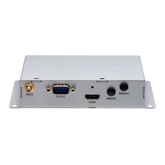
DB9 port used to connect serial devices. (Full RS232 signal) HDMI Used to connect an HDMI interface monitor. Antenna Holes Used to install external antennas. HDMI Antenna Antenna Holes Connector Copyright © 2022 NEXCOM International Co., Ltd. All Rights Reserved. VTC 210 Series User Manual... -
Page 21: Chapter 2: Jumpers And Switches
Humid environment tend to have less static electricity than dry environments. A grounding strap is warranted whenever danger of ▪ Use correct screws and do not over tighten screws. static electricity exists. Copyright © 2022 NEXCOM International Co., Ltd. All Rights Reserved. VTC 210 Series User Manual... -
Page 22: Jumper Settings
(on) and open (off). Two-Pin Jumpers: Open (Left) and Short (Right) Three-Pin Jumpers: Pins 1 and 2 are Short Copyright © 2022 NEXCOM International Co., Ltd. All Rights Reserved. VTC 210 Series User Manual... -
Page 23: Locations Of The Jumpers And Connectors
Chapter 2: Jumpers and Switches Locations of the Jumpers and Connectors Top View LED2 CN10 Copyright © 2022 NEXCOM International Co., Ltd. All Rights Reserved. VTC 210 Series User Manual... -
Page 24: Bottom View
Chapter 2: Jumpers and Switches Bottom View CN12 Copyright © 2022 NEXCOM International Co., Ltd. All Rights Reserved. VTC 210 Series User Manual... -
Page 25: Dip Switch Settings
Chapter 2: Jumpers and Switches DIP Switch Settings MCU Input Voltage Connector location: SW3 POWERSW (Pin1) 12V24V (Pin2) Result 9~36V Copyright © 2022 NEXCOM International Co., Ltd. All Rights Reserved. VTC 210 Series User Manual... -
Page 26: Connector Pin Definitions
Connector location: LAN1 Connector location: LAN2 Definition Definition Definition Definition LAN-1_MDI0P LAN-1_MDI0N LAN-2_MDI0P LAN-2_MDI0N LAN-1_MDI1P LAN-1_MDI2P LAN-2_MDI1P LAN-2_MDI2P LAN-1_MDI2N LAN-1_MDI1N LAN-2_MDI2N LAN-2_MDI1N LAN-1_MDI3P LAN-1_MDI3N LAN-2_MDI3P LAN-2_MDI3N Copyright © 2022 NEXCOM International Co., Ltd. All Rights Reserved. VTC 210 Series User Manual... -
Page 27: M12 Lan Connector
Connector location: CN4 Connector location: CN6 Definition Definition Definition Definition LAN-1_MDI0P LAN-1_MDI0N LAN-2_MDI0P LAN-2_MDI0N LAN-1_MDI1P LAN-1_MDI1N LAN-2_MDI1P LAN-2_MDI1N LAN-1_MDI3P LAN-1_MDI3N LAN-2_MDI3P LAN-2_MDI3N LAN-1_MDI2N LAN-1_MDI2P LAN-2_MDI2N LAN-2_MDI2P Copyright © 2022 NEXCOM International Co., Ltd. All Rights Reserved. VTC 210 Series User Manual... -
Page 28: Hdmi1 Connector
HDMI1_TX1+ HDMI2_TX2- HDMI2_TX1+ HDMI1_TX1- HDMI2_TX1- HDMI1_TX0+ HDMI2_TX0+ HDMI1_TX0- HDMI1_CLKD+ HDMI2_TX0- HDMI2_CLKD+ HDMI1_CLKD- HDMI2_CLKD- HDMI1_CEC HDMI2_CEC HDMI1_SCL HDMI1_SDA HDMI2_SCL HDMI2_SDA HDMI_PWR (VCC5) HDMI_PWR (VCC5) HDMI1_HPD HDMI2_HPD Copyright © 2022 NEXCOM International Co., Ltd. All Rights Reserved. VTC 210 Series User Manual... -
Page 29: Vga Connector (Bom Option Hdmi2)
Connector type: DB-15 port, 15-pin D-sub Connector location: SW1 Connector location: CN7 Definition Definition Definition VGA_R VGA_G VGA_B RSTBTN-IN# VGA_GND VGA_GND VGA_GND VGA_GND VGA_+5V VGA_GND VGA_SDA VGA_HSYNC VGA_VSYNC VGA_SCL Copyright © 2022 NEXCOM International Co., Ltd. All Rights Reserved. VTC 210 Series User Manual... -
Page 30: Power Button Connector
Chapter 2: Jumpers and Switches Power Button Connector Channel Switch Connector location: SW2 Connector location: SW4 Definition Definition Definition Definition PWRBT_IN# UP_SW DOWN_SW PWRBT_IN# LEDPWR_A1 LEDPWR_C1 Copyright © 2022 NEXCOM International Co., Ltd. All Rights Reserved. VTC 210 Series User Manual... -
Page 31: Flash Button
Chapter 2: Jumpers and Switches Flash Button SARADC Button Connector location: SW5 Connector location: SW6 Definition Definition FLASH_SW SARADC_SW Copyright © 2022 NEXCOM International Co., Ltd. All Rights Reserved. VTC 210 Series User Manual... -
Page 32: Pmic Reset Button
Chapter 2: Jumpers and Switches PMIC Reset Button PMIC Power On Button Connector location: SW7 Connector location: SW8 Definition Definition PMIC_RESET# PMIC_PWRON# Copyright © 2022 NEXCOM International Co., Ltd. All Rights Reserved. VTC 210 Series User Manual... -
Page 33: Usb2.0 Connector
Connector type: USB 2.0 ports, Type A Connector type: Earphone jack single port Connector location: CN8 Connector location: CN9 Definition Definition Definition Definition VCC5 USB_DN AGND LINE2_OUT_L_CA USB_DP LINE2_OUT_R_CA AGND Copyright © 2022 NEXCOM International Co., Ltd. All Rights Reserved. VTC 210 Series User Manual... -
Page 34: Internal Connectors
Connector size: 1 x 3 = 3-pin header Connector size: 1 x 2 = 2-pin header Connector location: CN10 Connector location: CN11 Definition Definition Definition Definition GND_IN V_IN VCC12 IGNITION Copyright © 2022 NEXCOM International Co., Ltd. All Rights Reserved. VTC 210 Series User Manual... -
Page 35: Rtc Battery Connector
Connector size: 1 x 10 = 10-pin header Connector location: J7 Connector location: J6 Definition Definition Definition COM1_GND COM1_GND VBAT1 SP_CTS_1 SP_DSR_1 SP_DTR_1 SP_RXD_1 SP_RI_1 SP_RTS_1 SP_TXD_1 SP_DCD_1 Copyright © 2022 NEXCOM International Co., Ltd. All Rights Reserved. VTC 210 Series User Manual... -
Page 36: Usb Otg Wafer
Connector size: 1 x 5 = 5-pin header Connector location: CN12 Connector location: J2 Definition Definition Definition Definition VCC5 OTG_DN UIM_PWR_A UIM_RST_A OTG_DP USB_OTG_ID UIM_CLK_A UIM_DAT_A SIM-DET1 Copyright © 2022 NEXCOM International Co., Ltd. All Rights Reserved. VTC 210 Series User Manual... -
Page 37: Sd Card Slot
Connector size: 1 x 3 = 3-pin header Connector location: J3 Definition Definition Definition MMC0_DAT2_SD MMC0_DAT3_SD DE TX MMC0_CMD_SD SD_CON_3V3 MMC0_CLK_SD DE RX MMC0_DAT0_SD MMC0_DAT1_SD MMC0_CD_SD Copyright © 2022 NEXCOM International Co., Ltd. All Rights Reserved. VTC 210 Series User Manual... -
Page 38: Gps Signal Connector
Connector size: 1 x 6 = 6-pin header Connector location: J4 Connector location: J1 Definition Definition GPS_BAT Definition Definition GPS_TXD GPS_RXD USB_VCC5 USB_DN VCC3_GPS USB_DP WLAN_LED# WLAN_DIS# Copyright © 2022 NEXCOM International Co., Ltd. All Rights Reserved. VTC 210 Series User Manual... -
Page 39: Mcu Debug Port
Connector size: 1 x 3 = 3-pin header Connector size: 2 x 4 = 8-pin header Connector location: JP1 Connector location: JP2 Definition Definition Definition MCU-TX2 +V3.3ALW MCU_NRST MCU-RX2 MCU_SWCLK MCU_SWDIO Copyright © 2022 NEXCOM International Co., Ltd. All Rights Reserved. VTC 210 Series User Manual... -
Page 40: M.2 3042 Key B Socket
POWER_OFF# USB_0P W_DISABLE1# USB_0N LTE_LED#_A PCIE_DIS CONFIG_0 VBUS_SENSE LTE_WAKE# W_DISABLE2# USB3_RX1N UIM_RST_A SIM-DET USB3_RX1P UIM_CLK_A UIM_DAT_A M2_RSET#_R_A USB3_TX1N UIM_PWR_A CONFIG_1 VCC3 USB3_TX1P VCC3 VCC3 CONFIG_2 Copyright © 2022 NEXCOM International Co., Ltd. All Rights Reserved. VTC 210 Series User Manual... -
Page 41: Chapter 3: System Setup
1. The screws circled on the bottom are used to secure the chassis. Remove these screws and put them in a safe place for later Bottom View Top View Copyright © 2022 NEXCOM International Co., Ltd. All Rights Reserved. VTC 210 Series User Manual... -
Page 42: Installing A Wlan Module
2. Tear off the 3M tape protective film and fix the WLAN module with 3M another end of the cable into USB WLAN module. tape. Copyright © 2022 NEXCOM International Co., Ltd. All Rights Reserved. VTC 210 Series User Manual... -
Page 43: Installing A Wwan Module (Mini-Pcie)
Mini PCI Express slot at a 45 degrees angle until the gold-plated connector on the edge of the module completely disappears inside the slot. Then fasten a screw into the mounting hole to secure the module. Copyright © 2022 NEXCOM International Co., Ltd. All Rights Reserved. VTC 210 Series User Manual... -
Page 44: Installing A Sim Card And Microsd Card
1. Insert the MicroSD card (CN1) and the SIM card (CN12). Please take note of the MicroSD card and SIM card installation direction as shown in the following picture. Micro-SIM MicroSD Copyright © 2022 NEXCOM International Co., Ltd. All Rights Reserved. VTC 210 Series User Manual... -
Page 45: Appendix A: Gps Feature
Qualification tests are performed as stipulated in the ISO16750 lowest noise figure (NEO-M8N/Q) standard: “Road vehicles – Environmental conditions and testing for electrical and electronic equipment”. Copyright © 2022 NEXCOM International Co., Ltd. All Rights Reserved. VTC 210 Series User Manual... - Page 46 C compliant) Baud Rate: 9600 Digital I/O Configurable timepulse 1 EXTINT input for Wakeup Timepulse Configurable 0.25 Hz to 10 MHz Protocols NMEA, UBX binary, RTCM Copyright © 2022 NEXCOM International Co., Ltd. All Rights Reserved. VTC 210 Series User Manual...
Need help?
Do you have a question about the VTC 210 Series and is the answer not in the manual?
Questions and answers