
Related Manuals for Nexcom X103


Summary of Contents for Nexcom X103
- Page 1 NEXCOM International Co., Ltd. Intelligent Platform & Services Business Unit Embedded Computing (Industrial Motherboard) X103 User Manual NEXCOM International Co., Ltd. www.nexcom.com Published September 2024...
-
Page 2: Table Of Contents
COM3, COM4 COM5, COM6 (RS232) ..........14 Key Features ...................1 80 Debug Port Connector ..............15 Hardware Specifications ................2 Fan Connector ...................15 Knowing Your X103 ................4 GPIO Connector ................16 Edge I/O View..................5 Copyright © 2024 NEXCOM International Co., Ltd. All Rights Reserved. X103 User Manual... - Page 3 When to Configure the BIOS ..............21 Default Configuration ................22 Entering Setup ..................22 Legends ....................22 BIOS Setup Utility ..................24 Main ....................24 Advanced ..................25 Security .....................32 Boot ....................33 Save & Exit ..................34 Copyright © 2024 NEXCOM International Co., Ltd. All Rights Reserved. X103 User Manual...
-
Page 4: Preface
Acknowledgements The product(s) described in this manual complies with all applicable X103 is a trademark of Nexcobot Co., Ltd. All other product names European Union (CE) directives if it has a CE marking. For computer systems mentioned herein are registered trademarks of their respective owners. -
Page 5: Rohs Compliance
NexCOBOT are renowned. The model selection criteria will be based on market demand. Vendors and suppliers will ensure that all designed components will be RoHS compliant. Copyright © 2024 NEXCOM International Co., Ltd. All Rights Reserved. X103 User Manual... -
Page 6: Warranty And Rma
“Out of Warranty.” ▪ Any products returned by NexCOBOT to other locations besides the customers’ site will bear an extra charge and will be billed to the customer. Copyright © 2024 NEXCOM International Co., Ltd. All Rights Reserved. X103 User Manual... - Page 7 ESD workstation. If no such station is available, you can provide some ESD protection by wearing an antistatic wrist strap and attaching it to a metal part of the computer chassis. Copyright © 2024 NEXCOM International Co., Ltd. All Rights Reserved. X103 User Manual...
-
Page 8: Safety Information
There is a danger of explosion if battery is incorrectly replaced. Replace only with the same or equivalent type recommended by the manufacturer. Discard used batteries according to the manufacturer’s instructions. viii Copyright © 2024 NEXCOM International Co., Ltd. All Rights Reserved. X103 User Manual... -
Page 9: Safety Precautions
11. Hold the board only by its edges. Be careful not to touch any of the components, contacts or connections. Copyright © 2024 NEXCOM International Co., Ltd. All Rights Reserved. X103 User Manual... -
Page 10: Technical Support And Assistance
1. Handling the unit: carry the unit with both hands and handle it with care. 2. Maintenance: to keep the unit clean, use only approved cleaning products or clean with a dry cloth. Copyright © 2024 NEXCOM International Co., Ltd. All Rights Reserved. X103 User Manual... -
Page 11: Global Service Contact Information
16F, No.250, Sec.2, Chongde Rd., Tel: +886-2-8226-7786 Tel: +886-2-8976-3077 Beitun District, Fax: +886-2-8226-7782 Email: sales@diviotec.com Taichung City, 406, Taiwan, R.O.C. Email: services@tmrtek.com www.diviotec.com Tel: +886-4-2249-1179 www.tmrtek.com Fax: +886-4-2249-1172 Email: jacobhuang@nexaiot.com www.nexaiot.com Copyright © 2024 NEXCOM International Co., Ltd. All Rights Reserved. X103 User Manual... - Page 12 9F, Tamachi Hara Bldg., LongGang District, 4-11-5, Shiba Minato-ku, ShenZhen, 518112, China Tokyo, 108-0014, Japan Tel: +86-755-8364-7768 Tel: +81-3-5419-7830 Fax: +86-755-8364-7738 Fax: +81-3-5419-7832 Email: steveyang@nexcom.com.tw Email: sales@nexcom-jp.com www.nexcom.cn www.nexcom-jp.com Copyright © 2024 NEXCOM International Co., Ltd. All Rights Reserved. X103 User Manual...
-
Page 13: Package Contents
Preface Package Contents Before continuing, verify that the X103 package that you received is complete. Your package should have all the items listed in the following table. Item Name X103 mainboard Heat Spreader: The heatspreader acts as a thermal coupling device to the module and is thermally coupled to the CPU via a thermal gap filler. On some modules, it may also be thermally coupled to other heat generating components with the use of additional thermal gap fillers. -
Page 14: Ordering Information
Preface Ordering Information The following information below provides ordering information for X103. X103-x6211E (P/N: 10W10X10300X0) Embedded computing board with Intel Atom x 6211E processor, with 1 x ® HDMI, 1 x LVDS, 3 x LAN, 6 x COM ports X103-x6413E (P/N: 10W10X10301X0) Embedded computing board with Intel Atom ®... -
Page 15: Chapter 1: Product Introduction
▪ 1 x M.2 Key B ▪ 1 x M.2 Key E ▪ 4 x USB port ▪ 6 x COM ▪ 1 x mini-PCIe slot ▪ Support dual power input, 12V/24V Copyright © 2024 NEXCOM International Co., Ltd. All Rights Reserved. X103 User Manual... -
Page 16: Hardware Specifications
▪ Relative humidity : 95% (non-condensing) ▪ 1 x mini-PCIe slot (PCIe, USB 2.0, SATA signal) ▪ 1 x SIM socket onboard, support Key B+M, 5G/LTE module Copyright © 2024 NEXCOM International Co., Ltd. All Rights Reserved. X103 User Manual... - Page 17 ▪ Windows 10 64-bit ® ▪ Linux™ Shipping Information ▪ Product weight (N.W): 1.6Kg ▪ Package weight (G.W): 2.8kg ▪ Carton dimension: 460mm x 373mm x 211mm Copyright © 2024 NEXCOM International Co., Ltd. All Rights Reserved. X103 User Manual...
-
Page 18: Knowing Your X103
Speaker Connector The image shown above is part of the same product series, and it is for reference only. The actual product may vary depending on the shipment. Copyright © 2024 NEXCOM International Co., Ltd. All Rights Reserved. X103 User Manual... -
Page 19: Edge I/O View
Chapter 1: Product Introduction Edge I/O View HDD Power Indicators 2.5GbE LAN Ports USB 2.0 HDMI 1.4 USB 3.2 Gen 2 Type A Copyright © 2024 NEXCOM International Co., Ltd. All Rights Reserved. X103 User Manual... -
Page 20: Chapter 2: Jumpers And Connectors
Chapter 2: Jumpers and Connectors 2: J haPter umPers and onneCtors This chapter describes how to set the jumpers and connectors on the X103 dry environments. A grounding strap is warranted whenever danger of motherboard. static electricity exists. Before You Begin Precautions ▪... -
Page 21: Jumper Settings
Refer to the illustrations below for examples of what the 2-pin and 3-pin jumpers look like when they are short (on) and open (off). Two-Pin Jumpers: Open (Left) and Short (Right) Three-Pin Jumpers: Pins 1 and 2 are Short Copyright © 2024 NEXCOM International Co., Ltd. All Rights Reserved. X103 User Manual... -
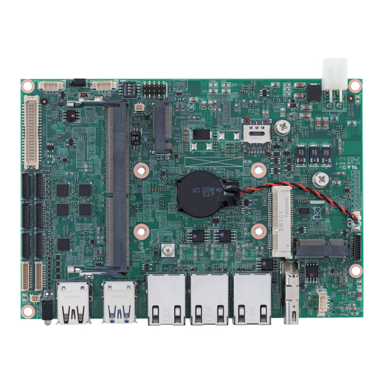
Page 22: Locations Of The Jumpers And Connectors
Locations of the Jumpers and Connectors The following figure shows the motherboard of X103, and indicates the locations of jumpers and connectors. Refer to this chapter for detailed pin setting and definitions of connectors marked in pink on this figure. -
Page 23: Jumpers
Connector type: DIP switch Connector type: 3-pin header Connector location: CLRCMOS Connector location: LCD_PWR Settings Settings 1-2 Off Normal (default) 1-2 On +3.3V (default) 3-4 On Clear CMOS 2-3 On Copyright © 2024 NEXCOM International Co., Ltd. All Rights Reserved. X103 User Manual... -
Page 24: Lvds/Edp Panel Edid Selection
8 bit 1400x1050 Dual 8 bit 1600x900 Dual 8 bit 1680x1050 Dual 8 bit 1600x1200 Dual 8 bit 1920x1080 Dual 8 bit OFF 1920x1200 (Default) Dual 8 bit Copyright © 2024 NEXCOM International Co., Ltd. All Rights Reserved. X103 User Manual... -
Page 25: Edge I/O Connector
Connector location: HDMI1 Connector location: DCIN_90D Definition Definition Definition HDMI1_TX2P HDMI1_TX2N HDMI1_TX1P +VIN HDMI1_TX1N +VIN HDMI1_TX0P HDMI1_TX0N HDMI1_CLK_P HDMI1_CLK_N HDMI1_SCL HDMI1_SDA HDMI1_P5V HDMI1_HPD CGND CGND CGND CGND Copyright © 2024 NEXCOM International Co., Ltd. All Rights Reserved. X103 User Manual... -
Page 26: Edge I/O Connector
1G/2.5G Blinking Yellow Steady Green 100M Blinking Yellow Steady Yellow LAN1_MDI1P LAN1_MDI1N Blinking Yellow TCTG No Active LAN1_MDI2P LAN1_MDI2N LAN1_MDI3P LAN1_MDI3N LAN1_LED_ACT_POWER LAN1_LED_ACT# LAN1_LED_LINK2500# LAN1_LED_LINK100# CGND CGND Copyright © 2024 NEXCOM International Co., Ltd. All Rights Reserved. X103 User Manual... -
Page 27: Usb 2.0 Connectors
Definition Definition Definition USB2_3N USB2_1N USB2_3P USB3_RX3N USB3_RX3P USB2_1P USB3_TX3N USB3_TX3P USB2_4N USB2_4P USB2_2N USB3_RX4N USB2_2P USB3_RX4P USB3_TX4N USB3_TX4P CGND CGND CGND CGND CGND CGND CGND CGND Copyright © 2024 NEXCOM International Co., Ltd. All Rights Reserved. X103 User Manual... -
Page 28: Internal Connector Pin Definitions
By default, COM1 and COM2 ports are RS485. You can change their function to RS232 or RS422 using a compatible COM cable and configure the Serial I/O Configuration setting in the BIOS. Copyright © 2024 NEXCOM International Co., Ltd. All Rights Reserved. X103 User Manual... -
Page 29: 80 Debug Port Connector
Connector type: 4-pin header Connector location: DEBUG Connector location: FAN Definition Definition Definition PLTRST# ESPI_CLK ESPI_CS# +12V ESPI_IO3 ESPI_IO2 FAN SPEED DETECT ESPI_IO1 ESPI_IO0 FAN SPEED CONTROL ESPI_RST# 3.3V Copyright © 2024 NEXCOM International Co., Ltd. All Rights Reserved. X103 User Manual... -
Page 30: Gpio Connector
Chapter 2: Jumpers and Connectors GPIO Connector Connector type: 10-pin header Connector location: GPIO Definition Definition GPO0 GPO1 GPO2 GPO3 GPI0 GPI1 GPI2 GPI3 Copyright © 2024 NEXCOM International Co., Ltd. All Rights Reserved. X103 User Manual... -
Page 31: Lvds Connector
LVDS_CLK1P +V_INV LVDS_DAT3N LVDS_DAT3P +V_PANEL +V_PANEL +V_PANEL LVDS_DAT4N LVDS_DAT4P LVDS_DAT5N LVDS_DAT5P INV_BKLTCTRL Hot-Plug Detect LVDS_DAT6N LVDS_DAT6P INV_BKLTEN LVDS_CLK2N LVDS_CLK2P LVDS_DAT0N LVDS_DAT0P LVDS_DAT7N LVDS_DAT7P LVDS_DAT1N LVDS_DAT1P Definition Definition Copyright © 2024 NEXCOM International Co., Ltd. All Rights Reserved. X103 User Manual... -
Page 32: Mic-In Line-Out Connector
System Power Button Connector type: 9-pin header Connector type: 2-pin header Connector location: MIC_LOUT Connector location: PWR_BTN Definition Definition LINE_OUT-R LINE_JD PWRBTN# AUDGND LINE_OUT-L AUDGND MIC_OUT-R MIC_JD MIC_OUT-L AUDGND Copyright © 2024 NEXCOM International Co., Ltd. All Rights Reserved. X103 User Manual... -
Page 33: Speaker Out Connector With Audio Amplifier
Speaker Out Connector with Audio Amplifier USB 2.0 Ports Connector type: 4-pin header Connector type: 10-pin header Connector location: SPK Connector location: USB2_45P Definition Definition Definition USB2_1N USB2_1P USB2_2P USB2_2N Copyright © 2024 NEXCOM International Co., Ltd. All Rights Reserved. X103 User Manual... -
Page 34: Block Diagram
Super I/O NCT6126D Watch dog GPIO F81439A F81439A F81437N F81437N F81437N F81437N 4I/4O Timer HW Monitor COM1 COM2 COM3 COM4 COM5 COM6 (RS232/422/485) (RS232/422/485) (RS232) (RS232) (RS232) (RS232) Copyright © 2024 NEXCOM International Co., Ltd. All Rights Reserved. X103 User Manual... -
Page 35: Chapter 3: Bios Setup
This chapter describes how to use the BIOS setup program for X103. The The settings made in the setup program affect how the computer performs. BIOS screens provided in this chapter are for reference only and may change It is important, therefore, first to try to understand all the setup options, and if the BIOS is updated in the future. -
Page 36: Default Configuration
Powering on the computer and immediately pressing <Del> allows you to enter Setup. Load optimized default values. Press the key to enter Setup: Saves and exits the Setup program. Press <Enter> to enter the highlighted sub-menu Copyright © 2024 NEXCOM International Co., Ltd. All Rights Reserved. X103 User Manual... - Page 37 When “” appears on the left of a particular field, it indicates that a submenu which contains additional options are available for that field. To display the submenu, move the highlight to that field and press Copyright © 2024 NEXCOM International Co., Ltd. All Rights Reserved. X103 User Manual...
-
Page 38: Bios Setup Utility
The Main menu is the first screen that you will see when you enter the BIOS hours from 00 to 23. Minute displays minutes from 00 to 59. Second displays Setup Utility. seconds from 00 to 59. Copyright © 2024 NEXCOM International Co., Ltd. All Rights Reserved. X103 User Manual... -
Page 39: Advanced
Setting incorrect field values may cause the system to malfunction. eDP/LVDS Support Enable or disable eDP/LVDS support. LVDS Panel Type Configure a resolution for the LVDS panel. Copyright © 2024 NEXCOM International Co., Ltd. All Rights Reserved. X103 User Manual... - Page 40 Select the number of cores to enable in each processor package. SATA Test Mode Intel(R) Speedstep(tm) Enable or Disable SATA Test mode. Enable or disable Intel Speedstep technology. Turbo Mode Enable or disable turbo mode. Copyright © 2024 NEXCOM International Co., Ltd. All Rights Reserved. X103 User Manual...
- Page 41 Platform Hierarchy Enable or disable Platform Hierarchy. Storage Hierarchy Enable or disable Storage Hierarchy. Endorsement Hierarchy Enable or disable Endorsement Hierarchy. Copyright © 2024 NEXCOM International Co., Ltd. All Rights Reserved. X103 User Manual...
- Page 42 ACPI Sleep State Select ACPI sleep state the system will enter when the suspend button is pressed. The options are Suspend Disabled and S3 (Suspend to RAM). Copyright © 2024 NEXCOM International Co., Ltd. All Rights Reserved. X103 User Manual...
- Page 43 Enable or disable this serial port (COM). Onboard Serial Port 1~6 Mode Specify a mode for the serial port, COM1/2 can be configured as RS232/ RS422/RS485, while COM3/4/5/6 can be configured as RS232. Copyright © 2024 NEXCOM International Co., Ltd. All Rights Reserved. X103 User Manual...
- Page 44 Press Enter to configure the smart fan function setting. Fixed Time: Set the system wake-up time in hours, minutes, or seconds. Dynamic Time: System will wake on the current time + increase minute(s) Copyright © 2024 NEXCOM International Co., Ltd. All Rights Reserved. X103 User Manual...
- Page 45 Enable or disable USB mass storage driver support. PXE boot wait time Configure the wait time in second to press the ESC key to abort the PXE boot. Copyright © 2024 NEXCOM International Co., Ltd. All Rights Reserved. X103 User Manual...
-
Page 46: Security
This section is used to configure the security related options for BIOS protection. Administrator Password Select this to configure the administrator’s password. User Password Select this to configure the user’s password. Copyright © 2024 NEXCOM International Co., Ltd. All Rights Reserved. X103 User Manual... -
Page 47: Boot
Adjust the boot sequence of the system. Boot Option #1 is the first boot device that the system will boot from, next will be Boot Option #2 and so forth. Copyright © 2024 NEXCOM International Co., Ltd. All Rights Reserved. X103 User Manual... -
Page 48: Save & Exit
Confirm by selecting “Yes“ and then exit the system setup. Discard Changes and Exit Press Enter to exit the BIOS without saving the changes. You may be prompted to confirm again before exiting. Copyright © 2024 NEXCOM International Co., Ltd. All Rights Reserved. X103 User Manual...
Need help?
Do you have a question about the X103 and is the answer not in the manual?
Questions and answers