
Related Manuals for Nexcom NDiS B533


Summary of Contents for Nexcom NDiS B533
- Page 1 NEXCOM International Co., Ltd. Intelligent Platform & Services Business Unit Digital Signage Platform NDiS B533 User Manual NEXCOM International Co., Ltd. www.nexcom.com Published January 2021...
-
Page 2: Table Of Contents
Front Panel ..................2 Internal Connectors ................15 Rear Panel ...................2 USB Connectors ................15 Hardware Specifications ................3 SIM Card Slot .................15 Mechanical Dimensions ................4 Debug 80 Port Connector ..............16 Copyright © 2013 NEXCOM International Co., Ltd. All Rights Reserved. NDiS B533 User Manual... - Page 3 When to Configure the BIOS ..............36 Default Configuration ................37 Entering Setup ..................37 Legends ....................37 BIOS Setup Utility ..................39 Main ....................39 Advanced ..................40 Boot ....................49 Security .....................49 Save & Exit ..................50 Copyright © 2013 NEXCOM International Co., Ltd. All Rights Reserved. NDiS B533 User Manual...
-
Page 4: Preface
No describes how to keep the system CE compliant. part of this manual may be reproduced, copied, translated or transmitted in any form or by any means without the prior written consent from NEXCOM Declaration of Conformity International Co., Ltd. -
Page 5: Rohs Compliance
(Cr6+) < 0.1% or 1,000ppm, Polybrominated biphenyls (PBB) < 0.1% or 1,000ppm, and Polybrominated diphenyl Ethers (PBDE) < 0.1% or 1,000ppm. In order to meet the RoHS compliant directives, NEXCOM has established an engineering and manufacturing task force to implement the introduction of green products. -
Page 6: Warranty And Rma
“NEXCOM RMA Service Form” for the RMA number apply process. ▪ If RMA goods can not be repaired, NEXCOM will return it to the customer without any charge. ▪ Customers can send back the faulty products with or without accessories (manuals, cable, etc.) and any components from the card, such as CPU... - Page 7 ESD workstation. If no such station is available, you can provide some ESD protection by wearing an antistatic wrist strap and attaching it to a metal part of the computer chassis. Copyright © 2013 NEXCOM International Co., Ltd. All Rights Reserved. NDiS B533 User Manual...
-
Page 8: Safety Information
▪ The instructions shall require connection of the equipment protective earthing conductor to the installation protective earthing conductor (for example, by means of a power cord connected to a socket-outlet with earthing connection). viii Copyright © 2013 NEXCOM International Co., Ltd. All Rights Reserved. NDiS B533 User Manual... -
Page 9: Safety Precautions
12Vdc, 8A or 8.33A minimum, Tma 40 degree power source to avoid damage by transient overvoltage. C minimum and altitude 2000m. If further assistance is needed, please contact NEXCOM for further information. Copyright © 2013 NEXCOM International Co., Ltd. All Rights Reserved. NDiS B533 User Manual... -
Page 10: Technical Support And Assistance
Preface Technical Support and Assistance Conventions Used in this Manual 1. For the most updated information of NEXCOM products, visit NEXCOM’s Warning: website at www.nexcom.com. Information about certain situations, which if not observed, can cause personal injury. This will prevent injury to yourself 2. -
Page 11: Global Service Contact Information
16F, No.250, Sec. 2, Chongde Rd., Beijing, 100094, China Beitun Dist., Tel: +86-10-5704-2680 Taichung City 406, R.O.C. Fax: +86-10-5704-2681 Tel: +886-4-2249-1179 Email: sales@nexcom.cn Fax: +886-4-2249-1172 www.nexcom.cn Email: sales@nexcom.com.tw www.nexcom.com.tw Copyright © 2013 NEXCOM International Co., Ltd. All Rights Reserved. NDiS B533 User Manual... - Page 12 Tokyo, 108-0014, Japan No. 609, Yunlin East Rd., Tel: +81-3-5419-7830 Shanghai, 200062, China Fax: +81-3-5419-7832 Tel: +86-21-5278-5868 Email: sales@nexcom-jp.com Fax: +86-21-3251-6358 www.nexcom-jp.com Email: renwang@nexcom.com.tw www.nexcom.cn Copyright © 2013 NEXCOM International Co., Ltd. All Rights Reserved. NDiS B533 User Manual...
-
Page 13: Package Contents
Preface Package Contents Before continuing, verify that the NDiS B533 package that you received is complete. Your package should have all the items listed in the following table. Item Part Number Name Description 50222A0438X00 NDiS 166 HDD-Bracket VER:A CHYUAN-JYH 95x9.8x8.0mm 0.8T SPCC+NI... -
Page 14: Ordering Information
Preface Ordering Information The following information below provides ordering information for NDiS B533. NDiS B533 (P/N: 10W00B53300X0) - 4th generation Intel Core™ processor (up to 35W) fanless system ® - Intel ® Q87 chipset NDiS B533F (P/N: 10W00B53301X0) - 4th generation Intel ®... -
Page 15: Chapter 1: Product Introduction
▪ 3 independent display ▪ USB 3.0, dual GbE LAN support ▪ WLAN/ TV tuner support NDiS B533 is a powerful digital signage player which is built around the ▪ DirectX 11.1 support superb technology of 4th generation Intel Core™ processor family series ®... -
Page 16: Physical Features
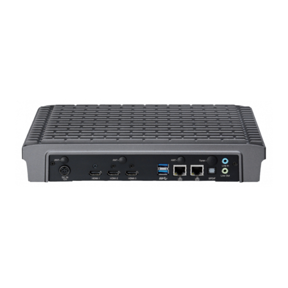
Physical Features Front Panel Rear Panel Power Button Line-in HDMI1 LAN LAN COM2 COM1 Power HDMI0 HDMI2 DC in USB 3.0 S/PDIF Line-out USB 3.0 Reset Copyright © 2013 NEXCOM International Co., Ltd. All Rights Reserved. NDiS B533 User Manual... -
Page 17: Hardware Specifications
▪ 3x antenna hole for Wi-Fi and TV tuner Operating System Storage ▪ Windows 7 / Windows 8 ▪ 1x SATA 2.5” HDD ▪ 1x SATA DOM Copyright © 2013 NEXCOM International Co., Ltd. All Rights Reserved. NDiS B533 User Manual... -
Page 18: Mechanical Dimensions
Chapter 1: Product Introduction Mechanical Dimensions 294.00 Copyright © 2013 NEXCOM International Co., Ltd. All Rights Reserved. NDiS B533 User Manual... -
Page 19: Chapter 2: Jumpers And Connectors
Static electricity can damage many of the electronic ▪ Use correct screws and do not over tighten screws. components. Humid environments tend to have less static electricity than Copyright © 2013 NEXCOM International Co., Ltd. All Rights Reserved. NDiS B533 User Manual... -
Page 20: Locations Of The Jumpers And Connectors For Ndib B533
Locations of the Jumpers and Connectors for NDiB B533 NDiB B533 The figure below is the top view of the NDiB B533, which is the mainboard used in the NDiS B533. It shows the locations of the jumpers and connectors. LED1 SW1... -
Page 21: Jumper Settings
(on) and open (off). Two-Pin Jumpers: Open (Left) and Short (Right) Three-Pin Jumpers: Pins 1 and 2 are Short Copyright © 2013 NEXCOM International Co., Ltd. All Rights Reserved. NDiS B533 User Manual... -
Page 22: Jumpers
Chapter 2: Jumpers and Connectors Jumpers RTC Clear Jump Connector type: 1x3 3-pin header, 2.54mm pitch Connector location: JP3 Settings 1-3 On Normal 2-3 On Clear CMOS 1-2 On: default Copyright © 2013 NEXCOM International Co., Ltd. All Rights Reserved. NDiS B533 User Manual... -
Page 23: Connector Pin Definitions
External I/O Interfaces - Front Panel Power Button LED Connector Connector location: SW2 Connector location: LED1 Power Power LED Definition LEDs LED Definition Blue Power Green Copyright © 2013 NEXCOM International Co., Ltd. All Rights Reserved. NDiS B533 User Manual... -
Page 24: Reset Button
Chapter 2: Jumpers and Connectors Reset Button COM1 and COM2 Connectors Connector location: SW1 Connector type: DB-9 port Connector location: J1 and J2 Definition Definition Definition System Reset Copyright © 2013 NEXCOM International Co., Ltd. All Rights Reserved. NDiS B533 User Manual... -
Page 25: Usb 3.0 Ports
USB 3.0 Ports Connector type: Dual USB 3.0 ports Connector location: USB1 Definition Definition USB0_N USB0_P USB3_RX0_N USB3_RX0_P USB3_TX0_N USB3_TX0_P USB1_N USB1_P USB3_RX1_N USB3_RX1_P USB3_TX1_N USB3_TX1_P Copyright © 2013 NEXCOM International Co., Ltd. All Rights Reserved. NDiS B533 User Manual... -
Page 26: External I/O Interfaces - Rear Panel
Connector location: CN7, CN8 and CN9 Definition Definition Definition Definition 12V DC_IN 12V DC_IN HDMI_D2+ HDMI_D2- HDMI_D1+ HDMI_D1- HDMI_D0+ HDMI_D0- HDMI_CLK+ HDMI_CLK- HDMI_DDC_SCL HDMI_DDC_SDA VCC5 HDMI_HPD Copyright © 2013 NEXCOM International Co., Ltd. All Rights Reserved. NDiS B533 User Manual... -
Page 27: Usb 3.0 Ports
Definition USB0_N TD4- USB0_P TD4+ TD3- USB3_RX0_N USB3_RX0_P TD3+ TD2- USB3_TX0_N TD2+ TD1- USB3_TX0_P TD1+ TCTG USB1_N USB1_P Left_LED+ Left_LED- USB3_RX1_N Right_LED+ Right_LED- USB3_RX1_P USB3_TX1_N USB3_TX1_P Copyright © 2013 NEXCOM International Co., Ltd. All Rights Reserved. NDiS B533 User Manual... -
Page 28: S/Pdif Connector
Connector type: S/PDIF Connector Connector type: 2x 3.5mm TRS Connector location: CN10 Connector location: CN6 Line-in Line-out Definition Definition SPDIF OUT Definition Definition FRONT-L FRONT-JD FRONT-R LINE-L LINE-JD LINE-R Copyright © 2013 NEXCOM International Co., Ltd. All Rights Reserved. NDiS B533 User Manual... -
Page 29: Internal Connectors
Connector type: 1x6 6-pin header JST, 2.0mm pitch Connector location: CN4 Connector location: J3 and J8 Definition Definition Definition Definition USB0_N UIM_PWR USB0_P USB1_N UIM_RST USB1_P UIM_CLK UIM_DAT Copyright © 2013 NEXCOM International Co., Ltd. All Rights Reserved. NDiS B533 User Manual... -
Page 30: Debug 80 Port Connector
Connector type: Standard Serial ATAII 7P (1.27mm, SATA-M-180) Connector location: J6 Connector location: CN3 Definition Definition Definition Definition SATA_TXP PCIRST# 33M_CLK LPC_FRAME# SATA_TXN SATA_RXN SATA_RXP LPC_AD3 LPC_AD2 LPC_AD1 LPC_AD0 3.3V 3.3V Copyright © 2013 NEXCOM International Co., Ltd. All Rights Reserved. NDiS B533 User Manual... -
Page 31: Sata Connector (7-Pin And 15-Pin)
Connector type: 1x4 4-pin header, 2.54mm pitch Connector location: SATA1 Connector location: CN2 Definition Definition Definition Definition SATA_TXP +12V SATA_TXN SATA_RXN SATA_RXP P1-3 P4-6 P7-9 VCC5 P10,12 P13-15 VCC12 Copyright © 2013 NEXCOM International Co., Ltd. All Rights Reserved. NDiS B533 User Manual... -
Page 32: Battery Connector
Connector type: 1x2 2-pin header JST, 1.25mm pitch Connector type: 2x5 10-pin header Connector location: J5 Connector location: JP1 Definition Definition Definition GPI1 GPO1 GPI2 GPO2 GPI3 GPO3 GPI4 GPO4 VCC5 Copyright © 2013 NEXCOM International Co., Ltd. All Rights Reserved. NDiS B533 User Manual... -
Page 33: Fan Connectors
Connector type: 1x4 4-pin header, 2.54mm pitch Connector type: 2x2 4-pin header Connector location: FAN1 and FAN2 Connector location: CON1 Definition Definition Definition Definition SPEED CONTROL 12V DC_IN 12V DC_IN Copyright © 2013 NEXCOM International Co., Ltd. All Rights Reserved. NDiS B533 User Manual... -
Page 34: Mini-Pcie Connector
Definition Definition Definition Definition WAKE# 3.3VSB 1.5V SMBCLK 1.5V PCIE_TX_N SMBDAT CLK_REQ# PCIE_TX_P USB_N PCIE_CLK# USB_P PCIE_CLK 3.3VSB 3.3VSB WLAN_DIS# RESET# 1.5V PCIE_RX_N 3.3VSB PCIE_RX_P 3.3VSB Copyright © 2013 NEXCOM International Co., Ltd. All Rights Reserved. NDiS B533 User Manual... -
Page 35: Mini-Pcie Connector
WAKE# 3.3VSB 1.5V SMBCLK 1.5V PCIE_TX_N SMBDAT CLK_REQ# UIM_PWR PCIE_TX_P UIM_DAT USB_N PCIE_CLK# UIM_CLK USB_P PCIE_CLK UIM_RST 3.3VSB 3.3VSB WLAN_DIS# RESET# 1.5V PCIE_RX_N 3.3VSB PCIE_RX_P 3.3VSB Copyright © 2013 NEXCOM International Co., Ltd. All Rights Reserved. NDiS B533 User Manual... -
Page 36: Chapter 3: System Setup
1. The screws on the back and bottom are used to secure the cover to the chassis. Remove these screws and put them in a safe place for later use. Copyright © 2013 NEXCOM International Co., Ltd. All Rights Reserved. NDiS B533 User Manual... -
Page 37: Installing A So-Dimm
2. Push the ejector tabs which are at the ends of the socket outward. This indicates that the socket is unlocked. 1. Locate the DIMM socket on the board. DIMM sockets Copyright © 2013 NEXCOM International Co., Ltd. All Rights Reserved. NDiS B533 User Manual... - Page 38 The ejector tabs at the ends of the socket will automatically snap into the locked position to hold the module in place. Notch Copyright © 2013 NEXCOM International Co., Ltd. All Rights Reserved. NDiS B533 User Manual...
-
Page 39: Installing The Cpu
▪ Make sure all power cables are unplugged before you install the CPU. CAUTION! CAUTION! CAUTION! ▪ The CPU socket must not come in contact with anything other than the CPU. Avoid unnecessary exposure. CPU socket Copyright © 2013 NEXCOM International Co., Ltd. All Rights Reserved. NDiS B533 User Manual... - Page 40 Thermal Pad Do not force the CPU into the socket. Forcing the CPU into the CAUTION! CAUTION! CAUTION! socket may bend the pins and damage the CPU. Copyright © 2013 NEXCOM International Co., Ltd. All Rights Reserved. NDiS B533 User Manual...
- Page 41 8. Align the mounting screws of the heat sink with the mounting holes on the board then tighten the screws to secure the heat sink in place. Mounting Mounting Screw hole Copyright © 2013 NEXCOM International Co., Ltd. All Rights Reserved. NDiS B533 User Manual...
-
Page 42: Installing A Sata Hard Drive
SATA drive with the mounting holes on the drive bracket. Then secure the SATA drive with screws. SATA Hard Drive Mounting Screw Copyright © 2013 NEXCOM International Co., Ltd. All Rights Reserved. NDiS B533 User Manual... - Page 43 4. Secure the SATA Drive with the provided mounting screw. 5. The mounting holes on the drive bracket and chassis are used to secure hard drive to the chassis. Mounting Studs Copyright © 2013 NEXCOM International Co., Ltd. All Rights Reserved. NDiS B533 User Manual...
- Page 44 SATA Data Connector SATA Power Connector SATA Power SATA Data Connector Connector Mounting Screw Copyright © 2013 NEXCOM International Co., Ltd. All Rights Reserved. NDiS B533 User Manual...
-
Page 45: Installing A Wireless Lan Module
1. Locate the Mini PCI Express slot on the board. Mini PCI Express Slot 3. Push the module down then secure it with mounting screws. Copyright © 2013 NEXCOM International Co., Ltd. All Rights Reserved. NDiS B533 User Manual... - Page 46 3. Attach the RF cables onto the Wi-Fi module, then mount the antenna jacks to the antenna holes located at the rear panel of the chassis. Then connect the external antennas to the antenna jacks. Antenna Copyright © 2013 NEXCOM International Co., Ltd. All Rights Reserved. NDiS B533 User Manual...
-
Page 47: Installing A Tv Tuner Module
1. Locate the Mini PCI Express slot on the board. 3. Push the module down then secure it with mounting screws. Mini PCI Express Slot Copyright © 2013 NEXCOM International Co., Ltd. All Rights Reserved. NDiS B533 User Manual... - Page 48 3. Attach the RF cables onto the TV tuner module, then mount the antenna jacks to the antenna holes located at the rear panel of the chassis. Then connect the external antennas to the antenna jacks. Antenna Copyright © 2013 NEXCOM International Co., Ltd. All Rights Reserved. NDiS B533 User Manual...
-
Page 49: Wall Mounting Instructions
4. Align the mounting holes on the sides of the mounting brackets with the predrilled holes on the mounting surface. 5. Insert four retention screws, two in each bracket, to secure the system to the wall. Copyright © 2013 NEXCOM International Co., Ltd. All Rights Reserved. NDiS B533 User Manual... -
Page 50: Chapter 4: Bios Setup
Chapter 4: BIOS Setup Chapter 4: BIOS Setup This chapter describes how to use the BIOS setup program for the NDiS B533. The settings made in the setup program affect how the computer performs. The BIOS screens provided in this chapter are for reference only and may It is important, therefore, first to try to understand all the setup options, and change if the BIOS is updated in the future. -
Page 51: Default Configuration
Powering on the computer and immediately pressing <Del> allows you to enter Setup. Load optimized default values. Press the key to enter Setup: Saves and exits the Setup program. Press <Enter> to enter the highlighted sub¬menu Copyright © 2013 NEXCOM International Co., Ltd. All Rights Reserved. NDiS B533 User Manual... - Page 52 When “” appears on the left of a particular field, it indicates that a submenu which contains additional options are available for that field. To display the submenu, move the highlight to that field and press Copyright © 2013 NEXCOM International Co., Ltd. All Rights Reserved. NDiS B533 User Manual...
-
Page 53: Bios Setup Utility
F3: Optimized Defaults ME Firmware SKU F4: Save & Exit ESC: Exit System Date [Fri 10/18/2013] System Time [14:46:01] Version 2.15.1236. Copyright (C) 2012 American Megatrends, Inc. Copyright © 2013 NEXCOM International Co., Ltd. All Rights Reserved. NDiS B533 User Manual... -
Page 54: Advanced
F1: General Help F2: Previous Values wake on the hr::min::sec specified. F3: Optimized Defaults F4: Save & Exit ESC: Exit Version 2.15.1236. Copyright (C) 2012 American Megatrends, Inc. Copyright © 2013 NEXCOM International Co., Ltd. All Rights Reserved. NDiS B533 User Manual... - Page 55 Select the highest ACPI sleep state the system will enter when the suspend Enables or disables Intel ® SpeedStep. button is pressed. The options are Suspend Disabled and S3 (Suspend to RAM). Copyright © 2013 NEXCOM International Co., Ltd. All Rights Reserved. NDiS B533 User Manual...
- Page 56 Configures the latency for C6. The options are Short and Long. CPU C7 Report Enables or disables C7 report to the operating system. C7 Latency Configures the latency for C7. The options are Short and Long. Copyright © 2013 NEXCOM International Co., Ltd. All Rights Reserved. NDiS B533 User Manual...
- Page 57 This option configures the Serial ATA drives to use AHCI (Advanced Host Controller Interface). AHCI allows the storage driver to enable the advanced Serial ATA features which will increase storage performance. Copyright © 2013 NEXCOM International Co., Ltd. All Rights Reserved. NDiS B533 User Manual...
- Page 58 RTC RAM Lock to power-on the system. Enables or disables RTC RAM lock. Power On When power returns after an AC power failure, the system will automatically power-on. Copyright © 2013 NEXCOM International Co., Ltd. All Rights Reserved. NDiS B533 User Manual...
- Page 59 Secondary IGFX Boot Display MEBx Selection Screen Select the secondary display device, the options are Disabled, HDMI1, Enables or disables MEBx selection screen. HDMI2 and HDMI3. Copyright © 2013 NEXCOM International Co., Ltd. All Rights Reserved. NDiS B533 User Manual...
- Page 60 Disables support for Legacy when no USB devices are connected. Disabled Keeps USB devices available only for EFI applications. USB 3.0 Support Enables or disables the USB 3.0 controller. Copyright © 2013 NEXCOM International Co., Ltd. All Rights Reserved. NDiS B533 User Manual...
- Page 61 F4: Save & Exit ESC: Exit Version 2.15.1236. Copyright (C) 2012 American Megatrends, Inc. Super IO Chip Displays the Super I/O chip used on the board. Copyright © 2013 NEXCOM International Co., Ltd. All Rights Reserved. NDiS B533 User Manual...
- Page 62 Smart Fan. System Temperature1 to System Temperature2 Detects and displays the internal temperature of the system. Core CPU Temperature(DTS) Detects and displays the current CPU temperature. Copyright © 2013 NEXCOM International Co., Ltd. All Rights Reserved. NDiS B533 User Manual...
-
Page 63: Boot
Adjust the boot sequence of the system. Boot Option #1 is the first boot device that the system will boot from, next will be #2 and so forth. Copyright © 2013 NEXCOM International Co., Ltd. All Rights Reserved. NDiS B533 User Manual... -
Page 64: Save & Exit
<Enter>. A dialog box will appear. Confirm by F3: Optimized Defaults F4: Save & Exit selecting Yes. ESC: Exit Version 2.15.1236. Copyright (C) 2012 American Megatrends, Inc. Copyright © 2013 NEXCOM International Co., Ltd. All Rights Reserved. NDiS B533 User Manual... -
Page 65: Appendix A: Watchdog Timer
Appendix A: Watchdog Timer Appendix A: Watchdog Timer NDiS B533 features a watchdog timer that resets the CPU or generates an interrupt if the processor stops operating for any reason. This feature ensures system reliability in industrial standalone or unmanned environments. - Page 66 0: Determined by WDT Time-out value select 1 (bit 7 of this register) WDT Output through PWEGD Enable 1: Enable 0: Disable During LRESET# this bit is selected by JP2 power-on strapping option. Interrupt level Select for WDT. Copyright © 2013 NEXCOM International Co., Ltd. All Rights Reserved. NDiS B533 User Manual...
-
Page 67: Appendix B: Gpi/O Programming Guide
Read data from GPI GPIO GPO3 GPO2 GPO1 GPI3 Step1: At Debug mode mapping Step2: Read Data at A02 (Input data is 1010) C:\debug -i A02 Copyright © 2013 NEXCOM International Co., Ltd. All Rights Reserved. NDiS B533 User Manual... -
Page 68: Appendix C: Triple Display Settings
Appendix C: Triple Display Settings Appendix C: Triple Display Settings NDiS B533 is capable of driving three displays from DisplayPort, HDMI, and DVI simultaneously. However, the default setting of Active Display in Intel ® Graphic and Media Control Panel is two. To use triple displays, please change it to three in Active Display.
Need help?
Do you have a question about the NDiS B533 and is the answer not in the manual?
Questions and answers