
Related Manuals for Siemens RUGGEDCOM RSG2300F


Summary of Contents for Siemens RUGGEDCOM RSG2300F
- Page 1 Preface Introduction Installing Device RUGGEDCOM RSG2300F Device Management Communication Ports Technical Specifications Installation Guide Certification 07/2018 RC1347-EN-02...
- Page 2 Warranty Siemens warrants this product for a period of five (5) years from the date of purchase, conditional upon the return to factory for maintenance during the warranty term. This product contains no user-serviceable parts. Attempted service by unauthorized personnel shall render all warranties null and void.
- Page 3 RUGGEDCOM RSG2300F Installation Guide Contacting Siemens Address Telephone E-mail Siemens Canada Ltd Toll-free: 1 888 264 0006 ruggedcom.info.i-ia@siemens.com Industry Sector Tel: +1 905 856 5288 300 Applewood Crescent Fax: +1 905 856 1995 Concord, Ontario https://www.siemens.com/ruggedcom Canada, L4K 5C7...
- Page 4 RUGGEDCOM RSG2300F Installation Guide...
-
Page 5: Table Of Contents
RUGGEDCOM RSG2300F Installation Guide Table of Contents Table of Contents Preface ......................Alerts ..............................vii Related Documents ..........................viii Accessing Documentation ........................viii Training ............................viii Customer Support ..........................viii Chapter 1 Introduction ..................... 1.1 Feature Highlights ........................1 1.2 Description ........................... 2 1.3 Required Tools and Materials ...................... - Page 6 RUGGEDCOM RSG2300F Table of Contents Installation Guide Chapter 4 Communication Ports ..................4.1 Copper Ethernet Ports ......................... 22 4.2 Fiber Optic Ethernet Ports ......................23 4.3 SFP Transceivers ......................... 24 4.4 GBIC Optic Ethernet Ports ......................25 4.4.1 Installing a GBIC Optical Port .................... 25 4.4.2 Removing a GBIC Optical Port ...................
-
Page 7: Preface
Installation Guide Preface Preface This guide describes the RUGGEDCOM RSG2300F. It describes the major features of the device, installation, commissioning and important technical specifications. It is intended for use by network technical support personnel who are responsible for the installation, commissioning and maintenance of the device. -
Page 8: Related Documents
Siemens Sales representative. Customer Support Customer support is available 24 hours, 7 days a week for all Siemens customers. For technical support or general information, contact Siemens Customer Support through any of the following methods: Online Visit http://www.siemens.com/automation/support-request... -
Page 9: Customer Support
RUGGEDCOM RSG2300F Installation Guide Preface • Contact a local Siemens representative from Sales, Technical Support, Training, etc. • Ask questions or share knowledge with fellow Siemens customers and the support community Customer Support... - Page 10 RUGGEDCOM RSG2300F Preface Installation Guide Customer Support...
-
Page 11: Introduction
(SFP, GBIC, LC, SC) without loss of port density. The RUGGEDCOM RSG2300F is packaged in a rugged galvanized steel enclosure with industrial grade DIN, panel, or 48 cm (19 in) rack-mount mounting options. -
Page 12: Description
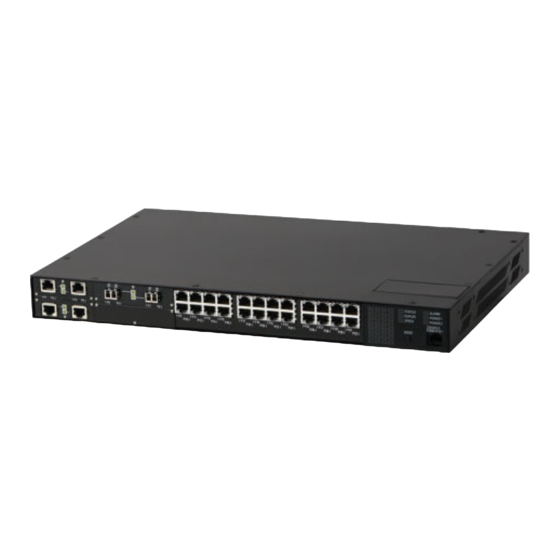
Section 1.2 Description The RUGGEDCOM RSG2300F features various ports, controls and indicator LEDs on the display panel for connecting, configuring and troubleshooting the device. The display panel can be located on the rear, front or top of the device, depending on the mounting configuration. -
Page 13: Required Tools And Materials
Section 3.1, “Connecting to the Device”. Section 1.3 Required Tools and Materials The following tools and materials are required to install the RUGGEDCOM RSG2300F: Tools/Materials Purpose AC power cord (16 AWG) For connecting power to the device. CAT-5 Ethernet cables For connecting the device to the network. -
Page 14: Decommissioning And Disposal
Siemens also does not recommend using copper Ethernet ports to interface with devices in the field across distances that could produce high levels of ground potential rise (i.e. greater than 2500 V), during line-to-ground fault conditions. -
Page 15: Gigabit Ethernet 1000Base-Tx Cabling Recommendations
RUGGEDCOM RSG2300F Chapter 1 Installation Guide Introduction Section 1.5.2 Gigabit Ethernet 1000Base-TX Cabling Recommendations The IEEE 802.3ab Gigabit Ethernet standard defines 1000 Mbit/s Ethernet communications over distances of up to 100 m (328 ft) using all 4 pairs in category 5 (or higher) balanced, unshielded twisted-pair cabling. For wiring... - Page 16 Chapter 1 RUGGEDCOM RSG2300F Introduction Installation Guide Supported Fiber Optic Cables...
-
Page 17: Installing Device
This product contains no user-serviceable parts. Attempted service by unauthorized personnel shall render all warranties null and void. Changes or modifications not expressly approved by Siemens Canada Ltd could invalidate specifications, test results, and agency approvals, and void the user's authority to operate the equipment. -
Page 18: Unpacking The Device
Mounting the Device The RUGGEDCOM RSG2300F is designed for maximum mounting and display flexibility. It can be equipped with connectors that allow it to be installed in a 48 cm (19 in) rack, 35 mm (1.4 in) DIN rail, or directly on a panel. -
Page 19: Mounting The Device To A Rack
Section 2.3.1 Mounting the Device to a Rack The RUGGEDCOM RSG2300F can be secured to a standard 48 cm (19 in) rack using separately purchased rack mount adapters. The adapters can be installed at the front or rear of the chassis. -
Page 20: Mounting The Device On A Din Rail
Mounting the Device on a DIN Rail For DIN rail installations, the RUGGEDCOM RSG2300F can be equipped with panel/DIN rail adapters pre-installed on each side of the chassis. The adapters allow the device to be slid onto a standard 35 mm (1.4 in) DIN rail. -
Page 21: Mounting The Device To A Panel
Section 2.3.3 Mounting the Device to a Panel For panel installations, the RUGGEDCOM RSG2300F can be equipped with panelDIN rail adapters pre-installed on each side of the chassis. The adapters allow the device to be attached to a panel using screws. -
Page 22: Connecting Power
The RUGGEDCOM RSG2300F supports a single or dual redundant AC and/or DC power supplies. The RUGGEDCOM RSG2300F can be equipped with either a screw-type or pluggable terminal block, which provides power to both power supplies. The screw-type terminal block is installed using Phillips screws and compression plates, allowing either bare wire connections or crimped terminal lugs. -
Page 23: Connecting Ac Or Dc Power
RUGGEDCOM RSG2300F Chapter 2 Installation Guide Installing Device • Section 2.5.2, “Wiring Examples” Section 2.5.1 Connecting AC or DC Power To connect a single high AC, high DC or low DC power supply to the device, do the following: CAUTION! Electrical hazard – risk of damage to equipment. Before testing the dielectric strength (HIPOT) in the field, remove the metal jumper. - Page 24 Chapter 2 RUGGEDCOM RSG2300F Installing Device Installation Guide Figure 6: Terminal Block Wiring 1. Screw-Type Terminal Block 2. Pluggable Terminal Block 3. Jumper 4. Positive/Live (+/L) Terminal 5. Negative/Neutral (-/N) Terminal (-/N) 6. Surge Ground Terminal 7. Chassis Ground Terminal Connect the negative wire from the power source to the negative/neutral (-/N) terminal on the terminal block.
-
Page 25: Wiring Examples
RUGGEDCOM RSG2300F Chapter 2 Installation Guide Installing Device Section 2.5.2 Wiring Examples The following illustrate how to connect power to single and dual power supplies. Figure 8: Single AC Power Supply Figure 9: Single DC Power Supply Wiring Examples... - Page 26 Chapter 2 RUGGEDCOM RSG2300F Installing Device Installation Guide Figure 10: Dual AC Power Supply Figure 11: Dual DC Power Supply Wiring Examples...
- Page 27 RUGGEDCOM RSG2300F Chapter 2 Installation Guide Installing Device Figure 12: Dual AC/DC Power Supply Wiring Examples...
- Page 28 Chapter 2 RUGGEDCOM RSG2300F Installing Device Installation Guide Wiring Examples...
-
Page 29: Device Management
Connecting to the Device The following describes the various methods for accessing the ROS-F console and Web interfaces on the device. For more detailed instructions, refer to the RUGGEDCOM ROS-F User Guide for the RUGGEDCOM RSG2300F. RS232 Console Port Connect a workstation directly to the RS232 console port to access the boot-time control and ROS-F interfaces. -
Page 30: Configuring The Device
Chapter 3 RUGGEDCOM RSG2300F Device Management Installation Guide Name Description Comment RJ45 Male Female Read to Send Ring Indicator The DSR, DCD and DTR pins are connected together internally. The CTS and RTS pins are connected together internally. RI is not connected. -
Page 31: Communication Ports
Chapter 4 Installation Guide Communication Ports Communication Ports The RUGGEDCOM RSG2300F can be equipped with various types of communication ports to enhance its abilities and performance. Module Assignment Figure 14: Module Assignment Each type of module has a specific location in the RUGGEDCOM RSG2300F chassis: •... -
Page 32: Copper Ethernet Ports
Section 4.1 Copper Ethernet Ports The RUGGEDCOM RSG2300F supports several 10/100/1000Base-TX Ethernet ports that allow connection to standard Category 5 (CAT-5) unshielded twisted-pair (UTP) cables with either RJ45 male connectors. The RJ45 connectors are directly connected to the chassis ground on the device and can accept CAT-5 shielded twisted-pair (STP) cables. -
Page 33: Fiber Optic Ethernet Ports
RUGGEDCOM RSG2300F Chapter 4 Installation Guide Communication Ports Name Description 10/100Base-TX 1000Base-TX BI_DB+ Transmit Data+ or Bi-Directional Pair B+ Reserved (Do BI_DC+ Transmit Data+ Not Connect) or Bi-Directional Pair C+ Reserved (Do BI_DC- Receive Not Connect) Data- or Bi- Directional Pair C-... -
Page 34: Sfp Transceivers
The RUGGEDCOM RSG2300F features two Small Form-Factor Pluggable (SFP) transceiver sockets, which are compatible with a wide array of SFP transceivers available from Siemens. The following SFP transceivers are compatible with the RUGGEDCOM RSG2300F. For more information, including RUGGEDCOM SFP Transceiver Catalog installation/removal instructions and ordering information, refer to the [https://support.industry.siemens.com/cs/ww/en/view/109482309]. -
Page 35: Gbic Optic Ethernet Ports
To install a GBIC optical port, do the following: CAUTION! Electrical hazard – risk of damage to equipment. Use only components certified by Siemens with RUGGEDCOM products. Damage to the module and device may occur if compatibility and reliability have not been properly assessed. -
Page 36: Removing A Gbic Optical Port
Installation Guide IMPORTANT! Only install GBIC optical ports that are compatible with the RUGGEDCOM RSG2300F. Make sure all potential electrostatic build-up has been properly discharged to prevent electrostatic discharges (ESD). This can be accomplished by wearing an ESD-preventive wrist strap connected to either the chassis ground connector or a bare metal surface on the router/switch. - Page 37 RUGGEDCOM RSG2300F Chapter 4 Installation Guide Communication Ports CAUTION! Electrical hazard – risk of damage to equipment. Make sure all electrostatic energy is dissipated before performing installing or removing components from the device. An electrostatic discharge (ESD) can cause serious damage to the component once it is outside the chassis.
- Page 38 Chapter 4 RUGGEDCOM RSG2300F Communication Ports Installation Guide Removing a GBIC Optical Port...
-
Page 39: Technical Specifications
Section 5.8, “Dimension Drawings” Section 5.1 Power Supply Specifications The RUGGEDCOM RSG2300F can be equipped with the following power supplies: CAUTION! Electrical hazard – risk of damage to the device. Disconnect the device from the power supply if power input is above or below the specified input range. -
Page 40: Failsafe Relay Specifications
NOTE • Maximum segment length is greatly dependent on factors such as fiber quality, and the number of patches and splices. Consult a Siemens sales associate when determining maximum segment distances. • All optical power numbers are listed as dBm averages. -
Page 41: Fiber Optic Ethernet Port Specifications
-11.2 14.2 Typical. Typical distance. The maximum distance is greatly dependent on factors such as cable type, the number of connectors and number of splices. Consult a Siemens sales associates when determining maximum distances. Fast Ethernet (10/100 Mbps) Optical Specifications... - Page 42 9/125 1310 Typical. Typical distance. The maximum distance is greatly dependent on factors such as cable type, the number of connectors and number of splices. Consult a Siemens sales associates when determining maximum distances. Gigabit Ethernet (1 Gbps) Optical Specifications NOTE These transceivers utilize a distributed feedback (DFB) type laser and are rated for -20 to 85 °C (-4 to...
-
Page 43: Operating Environment
All optical power numbers are listed as dBm averages. Typical distance. The maximum segment length is greatly dependent on factors such as fiber quality, and the number of patches and splices. Consult a Siemens sales associates when determining maximum segment distances. - Page 44 Chapter 5 RUGGEDCOM RSG2300F Technical Specifications Installation Guide NOTE Dimensional tolerances are in accordance with ISO 2768-mK, unless otherwise stated. 438.15 Figure 24: Overall Dimensions Dimension Drawings...
- Page 45 RUGGEDCOM RSG2300F Chapter 5 Installation Guide Technical Specifications 32.64 21.08 11.68 479.29 461.01 4.57 Figure 25: Rack Mount Dimensions Dimension Drawings...
- Page 46 Chapter 5 RUGGEDCOM RSG2300F Technical Specifications Installation Guide 486.4 476.3 10.4 11.7 Figure 26: Panel and DIN Rail Mount Dimensions Dimension Drawings...
-
Page 47: Certification
RUGGEDCOM RSG2300F Chapter 6 Installation Guide Certification Certification The RUGGEDCOM RSG2300F device has been thoroughly tested to guarantee its conformance with recognized standards and has received approval from recognized regulatory agencies. CONTENTS • Section 6.1, “Approvals” • Section 6.2, “EMC and Environmental Type Tests”... -
Page 48: European Union (Eu)
Information Technology Equipment – Radio Disturbance Characteristics – Limits and Methods of Measurement The device is marked with a CE marking and can be used throughout the European community. A copy of the CE Declaration of Conformity is available from Siemens Canada Ltd. For contact information, refer to “Contacting Siemens”. -
Page 49: Ised
Installation Guide Certification Section 6.1.5 ISED This device is declared by Siemens Canada Ltd to meet the requirements of the following ISED (Innovation Science and Economic Development Canada) standard: • CAN ICES-3 (A)/NMB-3 (A) Section 6.1.6 This device was designed and manufactured using a certified ISO (International Organization for Standardization) quality program that adheres to the following standard: •... -
Page 50: Emc And Environmental Type Tests
Chapter 6 RUGGEDCOM RSG2300F Certification Installation Guide Section 6.2 EMC and Environmental Type Tests The RUGGEDCOM RSG2300F has passed the following Electromagnetic Compatibility (EMC) and environmental tests. EMC Type Tests per IEC 61850-3 Test Description Test Levels Severity Levels IEC 61000-4-2 Enclosure Contact ±8 kV... - Page 51 EMC Immunity Type Tests per IEEE 1613 NOTE The RUGGEDCOM RSG2300F meets Class 2 requirements for an all-fiber configuration and Class 1 requirements for copper ports. Class 1 allows for temporary communication loss, while Class 2 requires error-free and interrupted communications.
- Page 52 Chapter 6 RUGGEDCOM RSG2300F Certification Installation Guide Description Test Levels Damped Oscillatory Enclosure Ports 100 A/m Magnetic Field Environmental Type Tests Test Description Test Levels IEC 60068-2-1 Cold Temperature Test Ad -40 °C (-40 °F), 16 Hours IEC 60068-2-2 Dry Heat Test Bd 85 °C (185 °F), 16 Hours...
Need help?
Do you have a question about the RUGGEDCOM RSG2300F and is the answer not in the manual?
Questions and answers