Advertisement

BlueHelix HiTech RRT C
INSTRUCTIONS FOR USE, INSTALLATION AND MAINTENANCE
____________________________________
"BLUEHELIX HITECH RRT 24C" GC N° 47-267-74
"BLUEHELIX HITECH RRT 28C" GC N° 47-267-75
"BLUEHELIX HITECH RRT 34C" GC N° 47-267-76

Advertisement

Table of Contents
loading

Summary of Contents for Ferroli BlueHelix HiTech RRT C

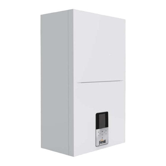
  • Page 1 BlueHelix HiTech RRT C INSTRUCTIONS FOR USE, INSTALLATION AND MAINTENANCE ____________________________________ "BLUEHELIX HITECH RRT 24C" GC N° 47-267-74 "BLUEHELIX HITECH RRT 28C" GC N° 47-267-75 "BLUEHELIX HITECH RRT 34C" GC N° 47-267-76...
  • Page 2 BlueHelix HiTech RRT C • Read the warnings in this instruction booklet ca- • Periodic maintenance performed by qualified refully since they provide important information personnel is essential in order to ensure proper on safe installation, use and maintenance. operation of the unit.
  • Page 3: Table Of Contents

    BlueHelix HiTech RRT C 1 Operating instructions ......................4 1.1 Introduction............................. 4 1.2 Control panel ............................4 1.3 Connection to the power supply, switching on and off ................7 1.4 Adjustments............................10 2 Installation ..........................18 2.1 General Instructions ..........................18 2.2 Place of installation ..........................
  • Page 4: Control Panel

    1.1 Introduction Dear Customer, BlueHelix HiTech RRT C is a high-efficiency, low emissions premix condensing heat generator with heat exchanger in s/steel and incorporated DHW production, equipped with a microprocessor control system. It can use Natural Gas (G20), Liquefied Gas (G30-G31), Propane Air (G230) and, thanks to the “Hydrogen plug-in”...
  • Page 5 BlueHelix HiTech RRT C Indication during operation Heating A heating request (generated by the Room Thermos- tat or Remote Timer Control) is indicated by the flas- hing radiator symbol. When the burner is lit, the flame symbol appears and the 3 levels indicate the actual intensity.
  • Page 6 BlueHelix HiTech RRT C Comfort In Comfort mode (restoration of boiler internal temperature) the flame symbol appears while the faucet flashes. Frost protection In frost protection mode (flow temperature below 5°C) the flame symbol appears. Fault In case of a fault, the display shows the fault code with different graphics depending on the type.
  • Page 7: Connection To The Power Supply, Switching On And Off

    BlueHelix HiTech RRT C 1.3 Connection to the power supply, switching on and off Boiler not electrically powered To avoid damage caused by freezing during long idle periods in winter, it is advi- sable to drain all the water from the boiler.
  • Page 8 BlueHelix HiTech RRT C Turning the boiler off and on Changing from one mode to another is possible by repeatedly pressing the button , following the sequence shown in fig. 11. A =“Summer” mode - B = “Winter” mode - C = “Off” mode To turn the boiler off, repeatedly press the button until detail C of fig.
  • Page 9: Adjustments

    BlueHelix HiTech RRT C 1.4 Adjustments Winter/summer switchover Repeatedly press the button until the summer symbol (sun) appears, with the word "OFF" for heating (detail 10 - fig. 1): the boiler will only deliver hot water. The frost protection system remains on.
  • Page 10 BlueHelix HiTech RRT C Room temperature adjustment (with optional room thermostat) Using the room thermostat, set the temperature required in the rooms. If the room thermostat is not installed, the boiler will keep the system at the set system delivery setpoint temperature.
  • Page 11 BlueHelix HiTech RRT C Installer menu [SERVICE] After selecting the installer menu [Service], press the button . To continue, enter the password “1234”. Use the buttons DHW to set the cell value, and the buttons heating to shift position (fig. 17).
  • Page 12 BlueHelix HiTech RRT C Boiler information menu [Diagnostic] This menu provides the information, in real time, of the various sensors present in the boiler. To access it, press the button from the main screen, select the item [Diagnostic] and confirm with the button...
  • Page 13 BlueHelix HiTech RRT C Boiler counters menu [Counters] The system counters are displayed in this menu: [Burner] COUNTERS Burner operation total hours. Burner [Ignition ok] Number of successful ignitions Ignition ok Ignition error [Ignition error] Number of failed ignitions. CH pump time...
  • Page 14 BlueHelix HiTech RRT C Display adjustment menu [Display] In this menu it is possible to set some display parame- DISPLAY ters. [Contrast] - Contrast adjustment Contrast [Brightness] - Brightness adjustment [Backlight time] - Display lighting duration Brightness [Lock time]* - Key lock...
  • Page 15 BlueHelix HiTech RRT C To exit the Climatic curves setting [OTC] menu, press the button repeatedly until reaching the main screen. If the room temperature is lower than the desired value, it is advisable to set a higher order curve and vice versa. Pro- ceed by increasing or decreasing in steps of one and check the result in the room.
  • Page 16 BlueHelix HiTech RRT C Display Description Operation Optimum pressure Normal operation Pressure slightly low The boiler continues to work. (The indication with the symbol It is advisable to refill the system as soon as possible. is visible only if parameter b09 is set to 1).
  • Page 17: Installation

    BlueHelix HiTech RRT C 2. Installation 2.1 General Instructions This unit must only be used for its intended purpose. This unit is designed to heat water to a temperature below boiling point and must be connected to a heating sys- tem and/or a water supply system for domestic use, compatible with its performan- ce, characteristics and its heating capacity.
  • Page 18: Place Of Installation

    BlueHelix HiTech RRT C 2.2 Place of installation The combustion circuit is sealed with respect to the place of installation and therefore the unit can be installed in any room except in a garage. The place of installation must be sufficiently ventilated to prevent the creation of dan- gerous conditions in case of even small gas leaks.
  • Page 19 BlueHelix HiTech RRT C Before installation, carefully flush all the heating system pipes to remove any residuals or impurities that could affect proper operation of the unit (as required by BS 7593 Building regs Doc L). Carry out the connections to the unit as indicated in .
  • Page 20 BlueHelix HiTech RRT C Make up water Provision must be made for replacing water lost from the sealed system. Reference should be made to BS6798, for methods of filling and making up sealed systems. There must be no direct connection between the boiler's central hea- ting system and the mains water supply.
  • Page 21: Gas Connection

    BlueHelix HiTech RRT C System water characteristics BlueHelix HiTech RRT C boilers are suitable for installation in heating systems with non-significant entry of oxygen (ref. systems "case I" EN14868). A physical separator (e.g. plate heat exchanger) must be provided in systems with continuous entry of oxygen (e.g. underfloor systems without antidiffusion pipes or open ves- sel), or intermittent (less than 20% of system water content).
  • Page 22: Electrical Connections

    BlueHelix HiTech RRT C 2.5 Electrical connections ATTENTION BEFORE CARRYING OUT ANY OPERATION REQUIRING REMOVAL OF THE CASING, DISCONNECT THE BOILER FROM THE ELECTRIC MAINS WITH THE MAIN SWITCH. NEVER TOUCH THE ELECTRICAL COMPONENTS OR CONTACTS WITH THE MAIN SWITCH TURNED ON! DANGER OF ELECTRIC SHOCK WITH RISK OF...
  • Page 23 BlueHelix HiTech RRT C Accessing the electrical terminal block and fuse Remove the front panel ( ”Opening the front panel” on page 38 ) to access the terminal block (M) and fuse (F) by pro- ceeding as follows (fig. 31 and fig. 32). The terminals indicated in fig. 31 must be with voltage-free contacts (not 230V).
  • Page 24: Fume Ducts

    BlueHelix HiTech RRT C Variable output relay card LC32 (optional - 043011X0) The variable output relay LC32 consists of a small card with a switchover of free contacts (closed means contact bet- ween C and NO). Operation is managed by the software.
  • Page 25 BlueHelix HiTech RRT C Connection with coaxial pipes fig. 33- Examples of connection with coaxial pipes ( = Air / = Fumes) For coaxial connection, fit the unit with one of the following starting accessories. For the wall hole dimensions, refer to the figure on the cover.
  • Page 26 BlueHelix HiTech RRT C Connection with separate pipes fig. 35- Examples of connection with separate pipes ( = Air / = Fumes) Table 6- Typology Type Description Wall horizontal exhaust and intake. The inlet/outlet terminals must be concentric or close enough to be subjected to similar wind conditions (within 50cm) Roof vertical exhaust and intake.
  • Page 27 BlueHelix HiTech RRT C Table 8- Accessories Losses in m Fume exhaust intake Vertical Horizontal PIPE 1 m M/F 1KWMA83W BEND 45° M/F 1KWMA65W 90° M/F 1KWMA01W PIPE SECTION with test point 1KWMA70W Ø 80 TERMINAL air, wall 1KWMA85A fumes, wall with antiwind...
  • Page 28 BlueHelix HiTech RRT C If the BlueHelix HiTech RRT C boiler is to be connected to a flue or a single chimney with natural draft, the flue or chimney must be expressly designed by professionally qualified technical personnel in conformity with the current re- gulations and be suitable for sealed chamber units equipped with fan.
  • Page 29: Condensate Drain Connection

    BlueHelix HiTech RRT C Minimum dimensions of fume exhaust terminals Horizontally from a terminal on the same wall 300 mm From the wall on which the terminal is fitted From a vertical structure on the roof 150 mm Above the intersection with the roof 300 mm •...
  • Page 30 BlueHelix HiTech RRT C Condensate drain If possible, the condensate should be conveyed inside an underground drainage system or pipe. For that purpose, use a pipe of at least 22 mm diameter and a trap with flexible connection preinstalled in the unit to facilitate connection of the condensate drain pipe.
  • Page 31: Service And Maintenance

    BlueHelix HiTech RRT C 3. Service and maintenance All adjustments described in this chapter can only be carried out by qualified personnel. 3.1 Adjustments Gas conversion The unit can work with 2 or 3 family gases, which is clearly indicated on the packaging and on the data plate of the unit.
  • Page 32 BlueHelix HiTech RRT C Calibration procedure [AUTO SETUP] 1. Access the parameters menu[TSP]. 2. Select parameter b27 with the hea- AUTO SETUP ting buttons and set it to 5 with the DHW buttons. Confirm with the button Return to the main menu[MENU].
  • Page 33 BlueHelix HiTech RRT C Test mode [Test] Do a heating or DHW request. 1. Access the Main menu [MENU] using the button TEST Follow the path installer menu [Service] >enter the Password 1234 (see fig. 17) >test mode menu [Test].
  • Page 34 BlueHelix HiTech RRT C Index Description Range Default 0 = Natural gas Gas type 1 = Liquefied gas 2 = Propane-air System water pressure protec- 0 = Pressure switch tion selection 1 = Pressure transducer 0 = WINTER - SUMMER - OFF...
  • Page 35 BlueHelix HiTech RRT C Index Description Range Default Restore Factory Values See ”* Restore Factory Values” on page 37 . 10÷80 Heating ramp (ex. 10=20°C/min, 20=12°C/min, 40=6°C/min, 80=3°C/min) Heating standby time 0 ÷ 10 minutes 0 ÷ 255 Heating Post-Circulation (Multiply the value by 10.
  • Page 36 BlueHelix HiTech RRT C Index Description Range Default G20/G230: 24 kW = 47 28 kW = 47 DO NOT MODIFY 34 kW = 49 Fan minimum speed (The parameters are automatically updated) G30/G31: 24 kW = 49 28 kW = 49...
  • Page 37: Commissioning

    BlueHelix HiTech RRT C 3.2 Commissioning Before lighting the boiler • Check the tightness of the gas system. • Check correct expansion vessel precharge. • Fill the hydraulic system and make sure that all air contained in the boiler and the system has been vented.
  • Page 38 BlueHelix HiTech RRT C To open the boiler casing: 1. Undo the screws “1” (see fig. 44). 2. Pull the panel outwards and lift it. fig. 44- Front panel opening On this unit, the casing also acts as a sealed chamber. After any operation involving opening the boiler, carefully check the correct refitting of the front panel and its seal.
  • Page 39 BlueHelix HiTech RRT C Periodical check To ensure proper operation of the unit over time, have qualified personnel carry out a yearly inspection, providing for the following checks: • The control and safety devices (gas valve, flow meter, thermostats, etc.) must function correctly.
  • Page 40 BlueHelix HiTech RRT C Extraordinary maintenance and replacement of components After replacing the gas valve, burner, electrode and PCB, it is necessary to do the calibration procedure [AUTO SE- TUP] (see “Calibration procedure [AUTO SETUP]” on page 32). Then follow the instructions in par. “Checking the com- bustion values”...
  • Page 41 BlueHelix HiTech RRT C Main exchanger replacement Before carrying out the following instructions it is advisable to protect the room and the boiler’s electrical box against accidental water spillage. Disconnect the power supply and close the gas cock ahead of the valve •...
  • Page 42 BlueHelix HiTech RRT C fig. 51 fig. 53 fig. 52 cod. 3541V691 - Rev. 00 - 04/2022...
  • Page 43 BlueHelix HiTech RRT C PCB replacement • Disconnect the power supply and close the gas cock ahead of the valve. • Undo the two screws “1” and rotate the control panel. • Raise the electrical box cover by operating on the tabs “2”...
  • Page 44 BlueHelix HiTech RRT C Fan replacement • Disconnect the power supply and close the gas cock ahead of the valve. • Remove the fan electrical connections. • Undo the screws “1” and gas pipe connection “2”. • Remove the venturi “3”.
  • Page 45: Troubleshooting

    BlueHelix HiTech RRT C Water inlet filter cleaning • Disconnect the power supply and close the gas cock ahead of the valve. • Isolate the boiler by operating the DHW inlet and system shut-off valves. • Clean the water inlet filter.
  • Page 46 BlueHelix HiTech RRT C Table of faults Table 11- List of faults Fault code Fault Possible cause Cure Check the regular gas flow to the boiler No gas and that the air has been eliminated from the pipes Check the wiring of the electrode and that...
  • Page 47 BlueHelix HiTech RRT C Fault code Fault Possible cause Cure No water circulation in the Check the circulating pump and heating system system Exchanger protection Poor circulation and ano- intervention malous flow probe tempera- Vent the system ture increase blocked exchanger...
  • Page 48 BlueHelix HiTech RRT C Fault code Fault Possible cause Cure Supply voltage under Electric mains trouble Check the electrical system 180V Wrong supply frequency Electric mains trouble Check the electrical system Pressure too low Fill the system Incorrect system water...
  • Page 49 BlueHelix HiTech RRT C Fault code Fault Possible cause Cure Check the gas supply, fume ducts and Specific flame combustion Unstable flame or unstable condensate drain. Check the correct posi- error flame signal after ignition. tion and state of the electrode After about 3 minutes the error is reset.
  • Page 50: Technical Data And Characteristics

    BlueHelix HiTech RRT C 4. Technical data and characteristics 4.1 Dimensions and connections fig. 61- Front view fig. 62- Side view fig. 64- Bottom view fig. 63- Top view Gas inlet - Ø 3/4” System return - Ø 3/4” DHW outlet - Ø 1/2”...
  • Page 51: General View

    BlueHelix HiTech RRT C 4.2 General view Safety valve Heating circulating pump Heating temperature sensor Automatic air vent DHW temperature probe Gas valve Expansion vessel Ionization/ignition electrode Diverter valve Flowmeter Water gauge Return sensor Fume temperature sensor Trap DHW exchanger...
  • Page 52: Technical Data Table

    BlueHelix HiTech RRT C 4.4 Technical data table Table 12- Technical data table cod. 3541V691 - Rev. 00 - 04/2022...
  • Page 53 BlueHelix HiTech RRT C cod. 3541V691 - Rev. 00 - 04/2022...
  • Page 54 BlueHelix HiTech RRT C cod. 3541V691 - Rev. 00 - 04/2022...
  • Page 55 BlueHelix HiTech RRT C cod. 3541V691 - Rev. 00 - 04/2022...
  • Page 56: Diagrams

    BlueHelix HiTech RRT C 4.5 Diagrams Residual head available for system BlueHelix HiTech RRT 24 C Q (m3/h) fig. 67- Residual head available for system BlueHelix HiTech RRT 28 C Q (m3/h) fig. 68- Residual head available for system BlueHelix HiTech RRT 34 C Q (m3/h) fig.
  • Page 57: Wiring Diagram

    BlueHelix HiTech RRT C 4.6 Wiring diagram 136 Flowmeter Heating circulating pump 138 External probe (optional) Heating temperature sensor 139 Remote timer control (optional) DHW temperature probe 186 Return sensor Gas valve 191 Fume temperature sensor Room thermostat (not supplied)
  • Page 58 Benchmark Commissioning and Servicing Section www.centralheating.co.uk © Heating and Hotwater Industry Council (HHIC)
  • Page 59 GAS BOILER SYSTEM COMMISSIONING CHECKLIST This Commissioning Checklist is to be completed in full by the competent person who commissioned the boiler as a means of demonstrating compliance with the appropriate Building Regulations and then handed to the customer to keep for future reference. CONTROLS Optimum start control Fitted...
  • Page 60 SERVICE RECORD It is that your heating system is serviced and that the appropriate Service Interval Record is completed. Service Provider SERVICE 01 SERVICE 02 ² % ² % ² % ² % SERVICE 03 SERVICE 04 ² % ² % ²...
  • Page 64 Before contacting Ferroli please have available the completed BENCHMARK document (located in the back of this manual), boiler serial number and model detail. For Technical assistance during the installation, call our Technical Helpline on 0 You will be required to provide your Gas Safe Register Number.

Table of Contents