Table of Contents
Advertisement
Quick Links
Advertisement
Table of Contents

Related Manuals for CNC4PC C34SGDM-BOARD


Summary of Contents for CNC4PC C34SGDM-BOARD
- Page 1 USER’S MANUAL VER. 1 C34SGDM-BOARD Rev. 3 OCTOBER 2020...
- Page 2 USER'S MANUAL TABLE OF CONTENTS Page # Contents OVERVIEW ........................1 FEATURES ........................1 BOARD DESCRIPTION ....................2 JUMPER TO SELECT THE ENABLE ................2 WIRING SAMPLE ......................4 Diagram of connection with input signals Step & Dir and C76......4 Diagram of connection with input signals Differentials C74 and C76.
- Page 3 OVERVIEW This board interface is used for the connection between C82, C76, M16D, C35S, C62 and the YASKAWA SGDM FEATURES • MDR PLUG 50POS R/A GOLD connector for Driver Connection. • RJ45 Connector for Axis. • Encoder Output. *NEW • Select Jumper for Hard Enable or Soft Enable. •...
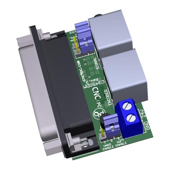
- Page 4 BOARD DESCRIPTION JUMPER TO SELECT THE ENABLE Use Software Enable to keep the driver active only while the system is active. Set of jumpers as shown in the image. SOFT ENABLE Use Hardware Enable to keep the driver enabled all the time. Set of jumpers as shown in the image.
- Page 5 HARD ENABLE JUMPER TO SELECT THE DIFFERENTIAL If working the inputs of STEP and DIR as differentials signals, you have to use the board, set jumper as shown in the image. DIFERENTIAL. If not use the differential signal for STEP & DIR, set jumper as show in the image. STEP &...
- Page 6 WIRING SAMPLE Diagram of connection with input signals Step & Dir and C76. Diagram of connection with input signals Differentials C74 and C76. User’s Manual Page 4...
- Page 7 PINOUT SGDM DRIVER AND C34SGDM CONNECT MDR 50POS PIN FUNCTION RJ45 PIN STEP+ INTERNAL STEP- ROUTER DIR+ INTERNAL DIR- ROUTER ALARM+ ALARM- 4(GND) SERVO ON NOT USED Note: Servo ON and Alarm signals are related to the RJ45 pin 5 of the C34SGDM board, but they are not connected directly to this pin.
- Page 8 DIMENSION All dimensions are in Millimeters. DISCLAIMER Use caution. CNC machines can be dangerous machines. Neither DUNCAN USA, LLC nor Arturo Duncan are liable for any accidents resulting from the improper use of these devices. This product is not a fail-safe device and it should not be used in life support systems or in other devices where its failure or possible erratic operation could cause property damage, bodily injury or loss of life.
Need help?
Do you have a question about the C34SGDM-BOARD and is the answer not in the manual?
Questions and answers