Advertisement
Quick Links
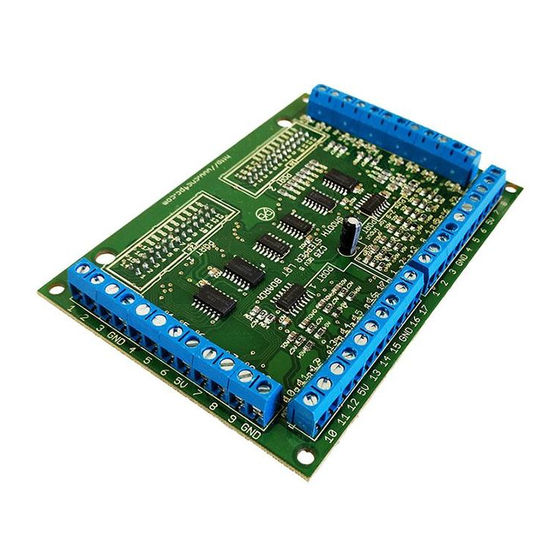
C25 (Rev. 1.1) User Manual
C25- SMOOTH STEPPER LPT BOARD Rev. 1.1
1. Overview
This board serves as a basic breakout board for the Smooth Stepper Board.
2.
Features
• 34 inputs and outputs on 2 ports.
• Connects directly to the Smooth
Stepper (from Warp9).
The board is provided with sockets
that allow the Smooth Stepper Board
Revision: 11/20/2009
User manual Rev. 1
http://cnc4pc.com/TechDocs/C25R1_1_User_Manual.pdf
Full access to all the pins of the
•
Smooth Stepper Board.
to be plugged directly into this board.
No ribbon cables required.
using the Smooth Stepper board
there is no need to use an additional
When
1/12
Advertisement

Related Manuals for CNC4PC C25


Summary of Contents for CNC4PC C25
- Page 1 C25 (Rev. 1.1) User Manual C25- SMOOTH STEPPER LPT BOARD Rev. 1.1 User manual Rev. 1 1. Overview This board serves as a basic breakout board for the Smooth Stepper Board. Features • 34 inputs and outputs on 2 ports.
-
Page 2: Specifications
C25 (Rev. 1.1) User Manual power supply power cards. 5VDC (TTL) cards are very common among automation devices. optoisolators, the board will draw power from the Smooth Stepper board. • Input and output pins with close by ground connections. Forget about grounding problems. -
Page 3: Functional Block Diagrams
Outputs 1, 14, 16 and 17 (Port 1 and 2). All those pins are directly routed to the C25 output terminals. Revision: 11/20/2009 http://cnc4pc.com/TechDocs/C25R1_1_User_Manual.pdf... -
Page 4: Wiring Diagrams
Note: The below wiring diagrams are an example, any input can be used for the connections. 5.1 Connecting Switches or push button. Fig. 3 Wiring diagram to connect switches. Note: The connection shown above works with any C25 input pin. Revision: 11/20/2009 http://cnc4pc.com/TechDocs/C25R1_1_User_Manual.pdf... - Page 5 5.2 Connecting NPN sensors. Fig. 7 Wiring diagram to connect NPN open collector proximity sensors. Fig. 8 Wiring diagram to connect in parallel NPN open collector proximity sensors. Connecting NPN open collector proximity sensor with the C25 R1 Value (12V) R1 Value (24V) Aprox.
- Page 6 Some NPN proximity sensor has a pull-up resistor (R1) internally. It is necessary to know its value in order to connect safely the sensor with the BOB. Follow this recommendation: Connecting NPN open collector proximity sensor with the C25 (R1+R2) Value (12V) (R1+R2) Value (24V) Aprox.
- Page 7 C25 (Rev. 1.1) User Manual Calculating the R1 value. Note: Being an unknown value resistor, in the follow explanation this resistor go to be named Rx. .(R/V) - R Where: is the external power supply voltage V is the voltage across the R resistor To calculate the internal resistor (Rx) values are required an external resistor and a voltmeter.
- Page 8 C25 (Rev. 1.1) User Manual 5.3 Connecting PNP sensors. Fig. 10 Wiring diagram to connect PNP proximity sensors Connecting PNP proximity sensor with the C24 R Value (12V) R Value (24V) Aprox. 10KΩ Aprox. 25KΩ Revision: 11/20/2009 http://cnc4pc.com/TechDocs/C25R1_1_User_Manual.pdf 8/12...
- Page 9 C25 (Rev. 1.1) User Manual 5.4 Other connection. Other connections can be implemented by setting the inputs with pull-up resistor. In this case connect an external 4.7KOhm resistor between the input terminal and the 5V terminal. Fig. 11 Wiring diagram to do an “Auto Tool Zero”...
-
Page 10: Troubleshooting
C25 (Rev. 1.1) User Manual 7. Troubleshooting. SYMPTOM 1: THE BOARD DOES NOT REACT TO THE SIGNAL. POSSIBLE CAUSE POSSIBLE SOLUTIONS Pin conflict or mach3 configuration. Check that the pin you are using is not It is possible that the port address been used anywhere else in your setup. - Page 11 C25 (Rev. 1.1) User Manual Carefully moving chips around and checking if the problem moves around could be a way of figuring out if this is the case. Revision: 11/20/2009 http://cnc4pc.com/TechDocs/C25R1_1_User_Manual.pdf 11/12...
- Page 12 Arturo Duncan are not liable for any accidents resulting from the improper use of these devices. The C25 is not fail-safe device, and it should not be used in life support systems or in other devices where its failure or possible erratic operation could cause property damage, bodily injury or loss of life.
Need help?
Do you have a question about the C25 and is the answer not in the manual?
Questions and answers