Table of Contents
Advertisement
Quick Links
Advertisement
Table of Contents

Related Manuals for CNC4PC C36S


Summary of Contents for CNC4PC C36S
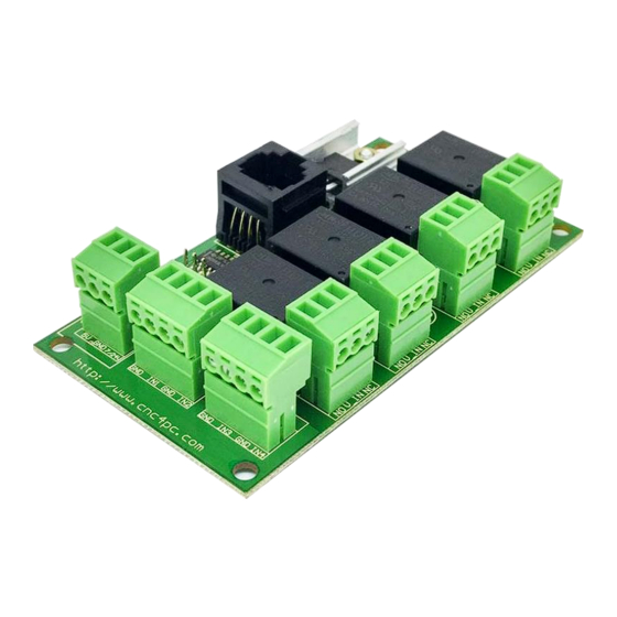
- Page 1 USER’S MANUAL VER.1 C36S – QUAD RELAY BOARD Rev. 1 MARCH 2018...
- Page 2 USER'S MANUAL TABLE OF CONTENTS Contents Page # OVERVIEW ........................1 FEATURES ........................1 BOARD DESCRIPTION ....................2 SPECIFICATIONS ......................2 Power Requirements ....................2 POWER BOARD ......................3 Terminal Power......................3 Connector RJ45 ......................3 RELAY SPECIFICATION ....................4 RJ45 PINOUT .........................
- Page 3 • Status LEDs on all relays connections. No more guessing. You can SEE all your signals. • All TTL +5VDC or +3.3VDC Signals. Interface directly with parallel port interface products and other cnc4pc.com cards. • *NEW*. Din Rail Mountable. User’s Manual...
- Page 4 BOARD DESCRIPTION SPECIFICATIONS Power Requirements It requires a +5VDC@200mA or +7-24V@200mA external power supply or voltage supplied by the RJ45 to operate. WARNING Check the polarity and voltage of the external power source and connect the 5V and GND. Overvoltage or reverse-polarity power applied to these terminals can cause damage to the board, and/or the power source.
- Page 5 POWER BOARD Terminal Power If used the terminal of power, set jumper as sample in the image Connector RJ45 If used the connector RJ45 to power the board, set jumper as sample in the image. User’s Manual Page 3...
- Page 6 RELAY SPECIFICATION ELECTROMECHANICAL RELAYS SPECIFICACTIONS Maximun Current (AC) 7A@240VAC; 10A@125VAC Maximum Current (DC) 15A@24VDC; 10A@28VDC RJ45 PINOUT RJ45 PIN FUNCTION RELAY 4 RELAY 3 RELAY 2 RELAY 1 NOT USED +5VDC NOT USED WIRING SAMPLE Note: This wiring is just to illustrate a sample product application. Specific wiring may vary from system to system.
- Page 7 DIMENSIONS All dimensions are in Millimeters. Fixing holes (3.8mm). Disclaimer: Use caution. CNC machines can be dangerous machines. Neither DUNCAN USA, LLC nor Arturo Duncan are liable for any accidents resulting from the improper use of these devices. This product is not a fail-safe device and it should not be used in life support systems or in other devices where its failure or possible erratic operation could cause property damage, bodily injury or loss of life.
Need help?
Do you have a question about the C36S and is the answer not in the manual?
Questions and answers