
Related Manuals for CNC4PC C86ACCP6


Summary of Contents for CNC4PC C86ACCP6
- Page 1 USER’S MANUAL VER.1 C86ACCP6 CleartPath Connector Board for the AcornSix 6-axis CNC controller Rev. 1 NOVEMBER 2022 User’s Manual Page 1...
-
Page 2: Table Of Contents
USER'S MANUAL TABLE OF CONTENTS Contents Page # OVERVIEW ........................3 FEATURES ........................3 BOARD DESCRIPTION ....................4 REQUIREMENTS ......................5 Power Requirements ....................5 TERMINAL POWER ....................... 5 ACTIVATING THE BOARD .................... 5 Operation Sequence: ....................6 JUMPER TO SELECT THE ACTIVE AXIS ..............7 JUMPER TO SELECT THE ENABLE ................ -
Page 3: Overview
OVERVIEW This board interface is used for the connection between AcornSix 6-axis CNC controller and the CLEARPATH SERVO DRIVE. FEATURES • Enable and disable the drives. • Splits Step and Direction signals from axis X or Y to allow wiring an additional axis using the same signals. -
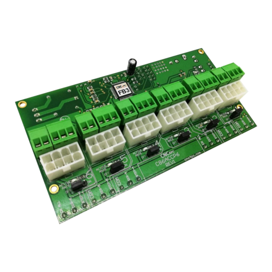
Page 4: Board Description
BOARD DESCRIPTION User’s Manual Page 4... -
Page 5: Requirements
REQUIREMENTS Power Requirements Regulated 24VDC@200mA is required to power this board. WARNING Check the polarity and voltage of the external power source and connect the 24VDC and GND. Overvoltage or reverse-polarity power applied to these terminals can cause damage to the board, and/or the power source. TERMINAL POWER Regulated 12 or +24VDC@200mA is required to power this board. -
Page 6: Operation Sequence
2. The contacts on the NO_FAULT terminal are closed. You can configure a relay and read the NO_FAULT signal from the ACORN, or you could just put a jumper on it if not used. The board can be activated by the axis enable or the NO_FAULT signal, or a combination of both signals. -
Page 7: Jumper To Select The Active Axis
JUMPER TO SELECT THE ACTIVE AXIS Set of jumpers as shown in the image 2-3: ON Set of jumpers as shown in the image 1-2: Set the jumper to ON for connected axis and off if no drivers are connected. Note: JUMPER TO SELECT THE ENABLE Use Software Enable to keep the driver active only while the system is active. -
Page 8: Led Indicator
LED INDICATOR When Status LED, (Green LED) lights, it indicates that the system is enabled. INDICATOR FAULT DETECTION User’s Manual Page 8... -
Page 9: Pinout
10.0 PINOUT CONTROL CABLE PIN ASSIGNMENTS PLUGGABLE TERMINAL FUNCTION COLOR NAME CLEAR PATH C86ACCP HLFB+ HLFB+ ALARM INPUT B+ STEP INPUT A+ DIRECTION ENABLE + ENABLE HLFB- INPUT B- INPUT A- ENABLE - User’s Manual Page 9... -
Page 10: Wiring Example Pluggable Terminal
11.0 WIRING EXAMPLE PLUGGABLE TERMINAL User’s Manual Page 10... -
Page 11: Wiring Example
12.0 WIRING EXAMPLE User’s Manual Page 11... -
Page 12: Dimensions
13.0 DIMENSIONS All dimensions are in Millimeters Fixing holes (3 mm) DISCLAIMER Use caution. CNC machines can be dangerous machines. Neither DUNCAN USA, LLC nor Arturo Duncan is liable for any accidents resulting from the improper use of these devices. This product is not a fail-safe device and it should not be used in life support systems or in other devices where its failure or possible erratic operation could cause property damage, bodily injury or loss of life.
Need help?
Do you have a question about the C86ACCP6 and is the answer not in the manual?
Questions and answers