Table of Contents
Advertisement
Quick Links
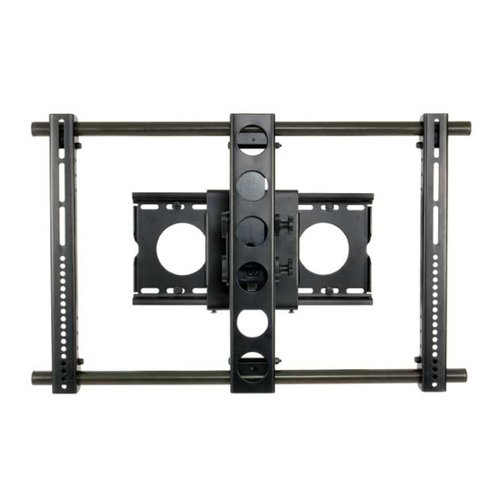
Assembly Instructions for Model: VMSA
Thank you for choosing a Sanus Systems Vision Mount wall mount. The VMSA is designed to mount up to 50" [1270 mm] Flat panel
televisions weighing up to 150 lbs. [68.2 Kg] to a vertical wall. It allows you to tilt the television from +5° to -15°. It will also extend 9.5"
[241 mm] away from the wall, swivel up to ± 30°, and roll ± 6°.
CAUTION: The size and weight of your large screen television must not exceed 50" [1270 mm] diagonally and 150 Lbs [68.2
Kg]. The wall must be capable of supporting five times the weight of the television plus the wall mount. Never use defective
parts. Improper installation may cause property damage or personal injury. Do not use this product for any purpose that is not
explicitly specified by Sanus Systems.
If you do not understand these directions, or have any doubts about the safety of the installation, please call a qualified contractor
or contact Sanus at 800.359.5520 or www.sanus.com. Our customer service representatives can quickly assist you with installation
questions and missing or damaged parts. Replacement parts for products purchased through authorized dealers will be shipped directly
to you. Check carefully to make sure that there are no missing or defective parts. Sanus Systems can not be liable for damage or injury
caused by incorrect mounting, incorrect assembly, or incorrect use. Please call Sanus Systems before returning products to the point of
purchase.
NOTE: The supplied wall mounting hardware is not for metal stud, concrete, brick, or block walls. If you are uncertain about the
nature of your wall, consult an installation contractor. Sanus makes every effort to assure all necessary television mounting
hardware is included. If the hardware you need is not included please consult your local hardware store or call Sanus
Systems.
Required Tools: 3/16" drill bit, drill, wrench set, phillips screwdriver
Supplied Parts: (Some parts not shown at same scale)
Wall Plate - A
Arm Assembly - B
Qty. 1
Qty. 1
1" Diameter Tube - C
Monitor Bracket - D
Vise Assembly - E
Qty. 2
Qty. 2
Qty. 4
Sanus Systems 2221 Hwy 36 West, Saint Paul, MN 55113 06.08.06 (6901-100071)
Customer Service: 800.359.5520. See complementary Sanus products at www.sanus.com
Advertisement
Table of Contents

Related Manuals for Sanus Systems VMSA


Summary of Contents for Sanus Systems VMSA
- Page 1 Assembly Instructions for Model: VMSA Thank you for choosing a Sanus Systems Vision Mount wall mount. The VMSA is designed to mount up to 50” [1270 mm] Flat panel televisions weighing up to 150 lbs. [68.2 Kg] to a vertical wall. It allows you to tilt the television from +5° to -15°. It will also extend 9.5”...
- Page 2 Hardware: (All threaded fasteners are shown full size) Wire Tie - G Wire Tie Clip - F Qty. 5 Qty. 2 Lag Bolt - H Lag Bolt Washer - I 7/32 & 3/16 Allen Keys - J Qty. 4 Qty. 4 Qty.
- Page 3 Step 1: Mounting Monitor Brackets to a television with a Flat Back NOTE: For TVs with a curved back or any other obstruction See Step 2. After completing this step, proceed to Step 3 Determine the diameter of the Bolt (N,O,P,Q) your TV requires by hand threading them into the threaded insert on the back of the TV. If you encounter any resistance stop immediately.
- Page 4 Step 2: Mounting the Monitor Brackets to a television with a curved back or any other obstruction. Determine the diameter of the Bolt (R,S,T,U) your TV requires by hand threading them into the threaded insert on the back of the TV. If you encounter any resistance stop immediately.
- Page 5 Step 3: Add the Vise Assemblies to the Monitor Brackets: NOTE: Do not overtighten the 1/4-20 Nut (L). The Vise Assembly (E) should be able to rotate freely around the Carriage Bolt (K). Place the Vise Assembly (E) between the two sides of the Monitor Bracket (D) so that the two jaws point toward the set of 1” diameter holes and the Allen Bolt is facing away from the television.
- Page 6 Step 4: Attach the Arm Assembly to the Television (Continued) CAUTION: The 1” Diameter Tubes (C) must extend beyond the outside edges of both Monitor Brackets (D) otherwise the installation will be unsafe and result in possible property damage and personal injury. Position the Arm Assembly (B) so that the hook shaped tab shown in the Detail View of Diagram 4B is on the top.
- Page 7 Step 6: Hang the assembly onto the Wall Plate CAUTION: This step may require two people to lift the assembly onto the Wall Plate. Sanus is not responsible for injury or damage. Orient the Arm Assembly (B) so that the arm extends directly away from the television and the Transfer Plate is parallel with the television. Lift the assembly, and hook the Transfer Plate onto the Tab on the top of the Wall Plate (A) as shown in Diagram 6A.
- Page 8 Step 8: Cable Management Before beginning wire management pull the television into the position as far from the wall as possible. Leave some slack in the cables so that during motion there is no added tension on the connectors. There are several places to attach wire management ties to keep cords out of the way.
Need help?
Do you have a question about the VMSA and is the answer not in the manual?
Questions and answers