Table of Contents
Advertisement
Quick Links
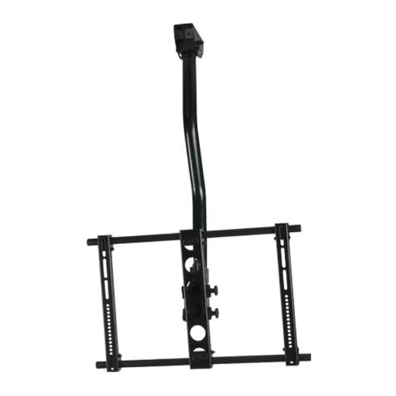
Assembly Instructions for Model: VMCM1
Thank you for choosing a Sanus Systems Vision Mount ceiling mount. The VMCM1 is designed to mount up to 50 inch flat panel televi-
sions weighing up to 130 lb. to an existing pipe drop. It allows you to tilt the television from +5° to -15°. It will also swivel up to ±90°,
and roll ±6°.
Safety Warning: If you do not understand these directions, or have any doubts about the safety of the installation, please call a quali-
fied contractor or contact Sanus at 800.359.5520 or www.sanus.com. Check carefully to make sure that there are no missing or defective
parts. Our customer service representatives can quickly assist you with installation questions and missing or damaged parts. Replace-
ment parts for products purchased through authorized dealers will be shipped directly to you. Never use defective parts. Improper instal-
lation may cause damage or serious injury. Do not use this product for any purpose that is not explicitly specified by Sanus Systems.
Sanus Systems can not be liable for damage or injury caused by incorrect mounting, incorrect assembly, or incorrect use. Please call
Sanus Systems before returning products to the point of purchase.
Required Tools: Phillips screw driver, wrench or socket set
Supplied Parts and Hardware: Some parts not shown at same size*
(1) Coupler - a*
(1) NPT Tube - b *
(1) Axis Assembly - c
(4) Vise Assembly - e *
(2) 1" Diameter Tube - d
(2) Monitor Bracket - f
Sanus Systems 2221 Hwy 36 West, St. Paul, MN 55113 10.18.05
Customer Service: 800.359.5520. See complementary Sanus products at www.sanus.com
Advertisement
Table of Contents

Subscribe to Our Youtube Channel
Related Manuals for Sanus Systems VMCM1


Summary of Contents for Sanus Systems VMCM1
- Page 1 Assembly Instructions for Model: VMCM1 Thank you for choosing a Sanus Systems Vision Mount ceiling mount. The VMCM1 is designed to mount up to 50 inch flat panel televi- sions weighing up to 130 lb. to an existing pipe drop. It allows you to tilt the television from +5° to -15°. It will also swivel up to ±90°, and roll ±6°.
- Page 2 Hardware: Not shown at actual size* (4) Carriage Bolt - g (4) 1/4 - 20 Nut - h (1) Security Bolt - i (2) Set Screw - j (5) Wire Tie Clip - k* (1) Allen Key - l (1) Allen Key - m TV Mounting Hardware: Shown as actual Size (4) M4 x 12 mm Bolt - n (4) M5 x 12 mm Bolt - o...
- Page 3 Step 1: Mounting Monitor Brackets to a television with a Flat Back First, determine the diameter of the Bolt (n,o,p,q) your TV requires by hand threading them into the threaded insert on the back of the TV. If you encounter any resistance stop immediately! Once you have determined the correct diameter, see the appropriate Diagram below. You will thread the Bolt through the appropriate Lock Washer (v,w,x,y), a Washer (z,aa), the Monitor Bracket (f) and finally into the TV.
- Page 4 Step 2: Mounting the Monitor Brackets to a television with a curved back or any other obstruction. First, determine the diameter of the Bolt (r,s,t,u) your TV requires by hand threading them into the threaded insert on the back of the TV. If you encounter any resistance stop immediately! Once you have determined the correct diameter, see the appropriate Diagram below.
- Page 5 Step 3: Add the Vise Assemblies to the Monitor Brackets: Note: Do not overtighten the 1/4-20 Nut. The Vise Assembly should be able to rotate freely around the Carriage Bolt. Place the Vise Assembly (e) between the two sides of the Monitor Bracket (f) so that the two jaws point toward the set of 1” diameter holes and the allen bolt is facing away from the television as shown in the Detailed View of Diagram 3.
- Page 6 Step 5: Attach the Axis Assembly (cont) Position the Axis Assembly (c) so that the allen bolts are facing away from the TV and the quick connect is on the top as shown in Dia- gram 5. Line up the two 1” diameter holes at the top and bottom of the Axis Assembly with the with the 1” Diameter Tubes (d). Continue to push the 1”...
- Page 7 Step 7: Attach the NPT Tube To attach the NPT Tube (b), simply thread the Coupler (a) onto an existing NPT Tube. Make sure the lower NPT Tube is oriented so the quick connect is facing toward the front as shown in the Side View of Diagram 7. Insert and tighten the Set Screws into each hole in the coupler with the Allen Key (l) as shown in the Detailed View of Diagram 7.
- Page 8 Ties to keep cables out of the way. You can attach them to the holes in the sides of the Monitor Brackets (f), the Axis Assembly (c) or around the NPT Tube (b). See Diagram 10 for assistance. Diagram 10 Detailed View Sanus Systems 2221 Hwy 36 West, St. Paul, MN 55113 10.18.05 Customer Service: 800.359.5520. See complementary Sanus products at www.sanus.com...
Need help?
Do you have a question about the VMCM1 and is the answer not in the manual?
Questions and answers