UpDown Desk PRO Series Set Up And Operation Manual
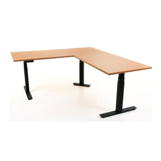
Corner desk
Hide thumbs
Also See for PRO Series:
- Set up and operation manual (25 pages) ,
- Setup and operation manual (23 pages) ,
- Install manual (22 pages)
Table of Contents
Advertisement
Quick Links
Advertisement
Table of Contents

Subscribe to Our Youtube Channel
Related Manuals for UpDown Desk PRO Series


Summary of Contents for UpDown Desk PRO Series
- Page 1 PRO Series Complete Guide to Simple Setup and Operation Corner Desk...
-
Page 2: Table Of Contents
Table of Contents Contents Introduction Pro-Series Corner Desk Frame Assembly 2.1. Contents 2.2 A note about screws/bolts 2.3 Step 1 2.3 Step 2 2.3 Step 3 2.3 Step 4 2.3 Step 5 2.3 Step 6 2.3 Step 7 2.3 Step 8 2.3 Step 9 2.3 Step 10 2.4 Desktops Installation... -
Page 3: Introduction
Introduction Congratulations on the purchase of your Pro-Series UpDown Corner Desk! You’ve made a significant investment into your health and wellbeing and your body will thank you for it. This instructional manual will guide you smoothly through the process of assembling the frame, attaching the optional cable tray and installing the desktops with the control panel. -
Page 4: Pro-Series Corner Desk Frame Assembly
Pro-Series Corner Desk Frame Assembly 2.1. Contents 1. 2 x regular feet 2. 1 x short corner foot 3. 2 x joining bars 4. 2 x pivot plates 5. 3 x legs 6. 1 x short corner wing 7. 2 x regular wings 8. -
Page 5: A Note About Screws/Bolts
2.2 A note about screws/bolts 2 bags of bolts/screws are also contained within the corner desk boxes. Bag 1 is a generic package covering several desk models whilst Bag 2 is specific to the corner desk. There may be some unused bolts/screws once assembly/installation is complete. - Page 6 Allen key required (supplied) Used to attach the legs to the wings/spreader bar, used to attached spreader bars to pivot plates. Self tapping screws 22 pieces in total Philips head screwdriver required (not supplied). Power drill optional (not supplied) Used to attach the frame, control panel and optional cable tray to the desktop(s)
-
Page 7: Step
2.3 Step 1 Note: The frame is being assembled upside-down initially as this is the simplest method. In this step you will be using: 2 x spreader bars 2 x legs 1 x regular wing 1 x regular foot 1 x short corner wing 1 x short corner foot 2 x pivot plates Arrange the parts as shown, ensuring the spreader bar control box tabs face inwards and the... - Page 8 2.3 Step 2 Using the Allen key provided, loosen (do not remove) the 8 pre-installed grub screws of the spreader bars as indicated below. The bars should be able to slide relatively freely.
-
Page 9: Step
2.3 Step 3 Install the first leg onto the spreader bars and regular wing using 6 x M8x10mm screws... -
Page 10: Step
2.3 Step 4 Moving to the second leg, install the pivot plates as shown using 3 x M8x10mm screws per pivot plate. Important: Each pivot plate has a step and must only be installed exactly as shown. - Page 11 The short corner wing can now be installed use 2 x M8 x 10mm screws...
-
Page 12: Step
2.3 Step 5 Install the pivot plate to the spreader bars using the holes as shown using 2 x M8x10mm screws. Do NOT tighten; the spreader bar must be able to pivot within the pivot plate slot at this point. -
Page 13: Step
2.3 Step 6 Attached both feet. The short foot uses 2 x M8x20mm screws and the regular foot uses 4 x M8x20mm screws. Flip the assembly over and position it as close as possible to its final desired location. - Page 14 In preparation for the next steps, it’s advisable to ensure the pivot-plate-to-spreader-bar angle is approximately 90 degrees as shown below.
-
Page 15: Step
2.3 Step 7 Assembly of the 3rd leg can now take place. In the same manner as Step 2 from earlier, ensure the spreader bar tabs are correctly positioned and adjacent to the ground. o Loosen (do not remove) 8 grub screws o Assemble spreader bar and regular wing onto the leg using 6 x M8x10mm screws o Assemble regular foot onto the leg using 4 x M8x20mm screws... -
Page 16: Step
2.3 Step 8 Flip the 3rd leg assembly and rest the spreaders bars on the pivot plate as shown. Accessing the frame from underneath, connect the spreader bar to the pivot plate using 2 x M8x10mm screws. Do not tighten at this point; the spreader bar should be able to pivot within the pivot plate slot. - Page 17 Once again, keep the spreader bar pivot plate of the 3 leg assembly at approximately 90 degrees as shown below.
-
Page 18: Step
2.3 Step 9 At this point it is necessary to determine where the control panel will go as this dictates the side the control box is mounted to. The control box should be mounted on the side closest to the future control panel location. -
Page 19: Step
2.3 Step 10 Install all cables. The short cable connects the control box to the closest motor, medium cable to the middle leg motor and long cable to the farthest leg. To assist with cable management later, it’s useful to run the long cable behind the middle motor as shown. Final cable management will occur later once the desktops have been installed. - Page 20 Plug the power cable into a 240v power source. The frame should now be operational. It’s useful to elevate the frame to a workable height that suits you for installing the desktops as you will need to work underneath the desk.
-
Page 21: Desktops Installation
2.4 Desktops Installation The following example assumes a 180cm desktop for the main desktop. Custom sizes will differ slightly, but the principles are the same. We now pre-configure the main desktop side. Per the earlier instructions, ensure the pivot plates are at right angles to the spreader bars. - Page 22 Now, extend the return side frame to suit your return desktop. Extend to 1.3 markings for a 120cm top and 1.6 markings for a 150cm top. It’s also advisable to keep the control box parallel to the spreader bars as shown by ensuring mounting tabs stay directly opposite one another. Place the return desktop on the frame ensuring it’s butted up to the main desktop.
- Page 23 A note about pre-drilling: Predrilling desktops can simplify the desktop installation process. It is not recommended to pre-drill Melamine desktops. Screwing into predrilled desktops is certainly far easier on Hardwood desktops such as Messmate, Vic Ash, Jarrah and Acacia. Whilst not necessarily, some customers report pre-drilling of Bamboo desktops also useful.
- Page 24 It is now time to finalise the position of the joined desktops assembly onto the frame. The frame should still be loose/moveable underneath the desktop as no spreader bar screws have been tightened and no self tapping desktop screws installed. You may need to wriggle the frame around to achieve the results described below.
- Page 25 Install 4 (four) self tapping screws firmly into the wing and spreader bar in the locations shown below. Repeat the aforementioned steps with the return desktop.
- Page 26 At this point assess the desk to ensure the frame is approximately square and centred. The centre leg should site at approximately 45 degrees to both other legs as shown below. There is a level of variability allowed and a few degrees off will not affect operation. If adjustment is required, there should still be enough movement within the frame to adjust its position.
-
Page 27: Control Panel Installation
2.5 Control Panel Installation One of the benefits of the electric Pro-Series desk is that it’s possible to locate the control panel wherever you wish. Most people situate it on the leading edge to the far right or left depending on their hand preference. -
Page 28: Cable Tray Installation (Optional Extra)
2.6 Cable Tray Installation (Optional extra) The cable tray can go wherever is practicable, depending on the location of your power points, your screen cables, your computer cables etc. It’s entirely up to you, however most people locate it underneath the desk, to the rear and in the middle. (Above example uses a 2 legged desk flipped upside down. -
Page 29: Control Panel Operation
2.7 Control Panel Operation The Pro Series desk can be raised manually by pressing the Up/Down buttons or alternatively by pressing pre-set heights using the M1 – M4 buttons. To set a height on any given ‘M’ button, use the Up/Down buttons to achieve your desired position. - Page 30 If you feel your desk’s downward anti-collision feature is being activated too soon or not soon enough, you can adjust its sensitivity. 1. Press and hold the ‘M4’ button for approximately 10 seconds until you hear the 2 audible beep. Release your finger from the button. The letter ‘A’ will be displayed. 2.
- Page 31 7. Press ‘M3’ twice to exit If you make any errors or need to start the above instructions again, simply press the ‘M3’ button twice. D - Minimum height setting If you have placed an obstruction under the desk such as pedestal drawers, you should set a minimum height.
- Page 32 If you make any errors or need to start the above instructions again, simply press the ‘M3’ button twice. F - ‘Up’ anti-collision sensitivity If you feel your desk’s upward anti-collision feature is being activated too soon or not soon enough, you can adjust its sensitivity.
-
Page 33: Troubleshooting
2.8 Troubleshooting Error Code Cause Solution (1) Turn power off at the power point. (2) Wait 60 seconds. Motor stoppage (3) Check cable connections. (4) Turn power back on. (1) Turn power off at the power point. (2) Wait 60 seconds. Legs not synchronised (3) Check cable connections. -
Page 34: Packaging Recycling And Disposal
2.9 Packaging recycling and disposal Your UpDown Desk products come packaged in cardboard boxes and lined with EPE foam (non- toxic) of various shapes/sizes. The cardboard is 100% recyclable and can be placed (with foam removed) into your local Council recycle bins or any carboard recycling station. At this time, there are currently no official recycling stations accepting EPE foam and it is not accepted in local Council recycle bins.
Need help?
Do you have a question about the PRO Series and is the answer not in the manual?
Questions and answers