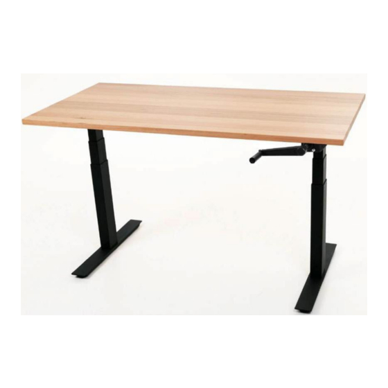
UpDown Desk PRO Series Setup And Operation Manual
Crank desk
Hide thumbs
Also See for PRO Series:
- Set up and operation manual (34 pages) ,
- Install manual (22 pages) ,
- Complete manual (16 pages)
Table of Contents
Advertisement
Quick Links
Advertisement
Table of Contents

Subscribe to Our Youtube Channel
Related Manuals for UpDown Desk PRO Series


Summary of Contents for UpDown Desk PRO Series
- Page 1 PRO Series Complete Guide to Simple Setup and Operation Manual Crank Desk...
-
Page 2: Table Of Contents
Table of Contents Contents Introduction PRO Series Manual Crank Desk Frame Assembly 2.1. Contents 2.2 A note about screws/bolts 2.3 Step 1 2.4 Step 2 2.4 Step 3 2.4 Step 4 2.4 Step 5 2.4 Step 6 2.4 Step 7 2.4 Step 8... -
Page 3: Introduction
Introduction Congratulations on the purchase of your PRO Series UpDown Manual Crank desk! You’ve made a significant investment into your health and wellbeing and your body will thank you for it. This instructional manual will guide you smoothly through the process of assembling the frame, installing the desktop and attaching the optional cable tray. -
Page 4: Pro Series Manual Crank Desk Frame Assembly
PRO Series Manual Crank Desk Frame Assembly 2.1. Contents 1. 1 x Spreader bar 2. 1 x regular wing 3. 1 x wing/crank assembly 4. 1 x crank handle 5. 1 x Bag of bolts/screws/Allen keys 6. 2 x legs 7. -
Page 5: 2.2 A Note About Screws/Bolts
2.2 A note about screws/bolts The bag of bolts/screws/Allen keys (#5) is a generic package covering several desk models. If you discover any screws beyond what is described in this setup manual, you may consider them spares. Below we describe each item within the bag and what it’s used for. M8 x 20mm 8 pieces in total Allen key #1 required... -
Page 6: Step
2.3 Step 1 Note: The frame will be assembled upside-down at first as this is the simplest method. Loosen (do not remove) the two shaft grub screws as shown of the wing/crank assembly using Allen key 2. The hex shaft within is then able to move in/out. Loosen the two bearing coupling screws as shown using Allen key 3. -
Page 7: Step
Assemble the regular wing on the leg 2 using two M8x10mm screws. 2.4 Step 3 Loosen 4 grub screws of the spreader bar and extend to expose 3 mounting holes on each side. -
Page 8: Step
2.4 Step 4 Set up the spreader bar in preparation to install onto each leg using six M8x10mm screws (3 each side). Ensure spreader bar tabs are facing down and flat on the ground (these tabs are used to install the desktop later). Do NOT re-tighten the grub screws of the spreader bar at this point! Take note below of the incorrect and correct spreader bar to leg attachment layout. -
Page 9: Step
2.4 Step 5 Install the feet on each leg using the eight M8x20mm screws (4 on either side) and Allen key 1. -
Page 10: Step
2.4 Step 6 Place the desk frame assembly on top of the underside of your desktop. Extend the entire assembly the appropriate length to suit your desktop. As a guide, a 5-10cm of gap between the edge of the desk and the wing is acceptable; they should be the same on both sides of the desk. Re-tighten the 4 grub screws of the spreader bar that you loosened earlier using Allen key 1. - Page 11 Install 6 self tapping screws through the tabs located below using a Phillips head screwdriver. Predrilling desktops can simplify the desktop installation process. It is not recommended to pre-drill Melamine desktops. Installation of predrilled desktops is certainly far easier on Hardwood desktops such as Messmate, Vic Ash, Jarrah and Acacia.
-
Page 12: Step
2.4 Step 7 Using Allen key 2, loosen (do not remove) the 4 screws of the horizontal crank shaft closet to the exposed shorter hex shaft end. This will allow you to extend the shaft to suit the width of the frame. -
Page 13: Step
2.4 Step 8 Ensuring the small hex shaft remains firmly within the leg, pull the crank shaft centre through the bearing housing in the direction shown and only by a similar amount as show below. -
Page 14: Step
2.4 Step 9 Install the crank handle into the crank assembly. Install a crank handle grub screw into the crank handle shaft as shown below. Tighten until it bottoms out, then back off ½ turn. This will allow the crank handle to move back and forth within the crank handle shaft, which is required if you want the crank handle hidden when not in use. -
Page 15: Step
2.4 Step 10 Using the palm of your hand, begin to gently tap the crank handle to install the outer shaft crank handle shaft onto the small hex shaft that remained within the leg in Step 8. Tap the handle only until the handle is just positioned under what will become the underside of the desk as shown below. - Page 16 The goal is to ensure the crank handle is situated completely under the desk when not in use and pulls out when you require a desk height change. Troubleshooting tip: if you have tapped too far and the crank handle does not clear the desk when extended, you will need pull the crank shaft centre through the bearing housing as seen in Step 8.
- Page 17 Tighten the 4 grub screws loosened off in Step 1, ie the two bearing coupling screws indicated below using Allen key 3 and two shaft grub screws of the wing/crank assembly using Allen key 2 (Note: if only 1 grub screw is visible, simply tighten this; it will suffice.)
-
Page 18: Step
2.4 Step 11 The crank handle clamp can now be installed on the underside of the desk using the 2 Clamp self tapping screws. Line up the crank handle within the clamp and mark the hole positions with a pencil. The clamp can now be installed. -
Page 19: Step
2.4 Step 12 Flip the desk about the NON-crank handle side (to avoid damage to the handle). Crank the handle in an anti-clockwise direction to raise the desk and clockwise direction to lower the desk. - Page 20 Note: If you wish to have the crank handle locked in position, ie cannot slide back and forth, there is an optional grub screw included that allows you to lock this in. 120cm desktops require the tubes to be adjusted inwards, as close to the tabs (with red/orange arrows) as possible.
-
Page 21: Cable Tray Installation (Optional Extra)
(Electric PRO Series model shown above for demonstrative purposes only) On one side of the cable tray, you will notice a thin, soft padding. This side always goes against the desk. -
Page 22: Appendices
Appendices Appendix A SPECIAL CAUTION: 1. The maximum allowable overhang of the front of desktop in relation to the side wing is 50mm. I.e. for a 750mm desktop, there will 50mm overhang at the front and a 100mm overhang at the rear in relation to the side supports of the frame (see diagram below). 2. -
Page 23: Packaging Recycling And Disposal
Packaging recycling and disposal Your UpDown Desk products come packaged in cardboard boxes and lined with EPE foam (non- toxic) of various shapes/sizes. The cardboard is 100% recyclable and can be placed (with foam removed) into your local Council recycle bins or any carboard recycling station. At this time, there are currently no official recycling stations accepting EPE foam and it is not accepted in local Council recycle bins.
Need help?
Do you have a question about the PRO Series and is the answer not in the manual?
Questions and answers