UpDown Desk PRO Series Complete Manual
Complete guide to simple setup and operation
Hide thumbs
Also See for PRO Series:
- Set up and operation manual (34 pages) ,
- Setup and operation manual (23 pages) ,
- Install manual (22 pages)
Table of Contents
Advertisement
Quick Links
Advertisement
Table of Contents

Related Manuals for UpDown Desk PRO Series


Summary of Contents for UpDown Desk PRO Series
- Page 1 PRO-Series Complete Guide to Simple Setup and Operation...
-
Page 2: Table Of Contents
Table of Contents Contents Introduction ................................3 Pro-Series Desk Frame Assembly .........................4 2.1. Contents ..............................4 2.2 A note about screws/bolts .........................5 2.3 Step 1 ................................6 2.4 Step 2 ................................7 2.5 Step 3 ................................8 2.6 Step 4 ................................9 Desktop Installation ............................10 Control Panel Installation .......................... -
Page 3: Introduction
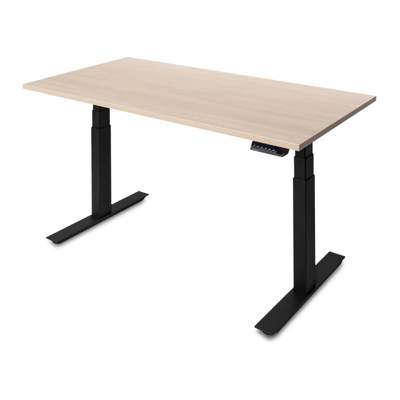
Introduction Congratulations on the purchase of your Pro-Series UpDown Desk! You’ve made a significant investment into your health and wellbeing and your body will thank you for it. This instructional manual will guide you smoothly through the process of assembling the frame, attaching the optional cable tray and installing the desktop with the control panel. -
Page 4: Pro-Series Desk Frame Assembly
Pro-Series Desk Frame Assembly 2.1. Contents 1. 2 x Legs 2. 2 x Feet 3. 2 x Wings 4. 2 x Adjustable tubes 5. 1 x Control box 6. 2 x Motor cables 7. 1 x Power cable 8. 1 x Allen key 9. -
Page 5: 2.2 A Note About Screws/Bolts
2.2 A note about screws/bolts The bag of bolts/screws (#9) is a generic package covering several desk models. Therefore, there will be some unused bolts/screws once assembly/installation is complete. There may also be an extra screw or two in the bag of self-tapping screws (#10). Below we describe each bolt and what it’s used for. -
Page 6: Step 1
2.3 Step 1 Note: The frame is being assembled upside-down at first as this is the simplest method. Using the Allen key (#8) provided, loosen (don’t remove) the 8 pre-installed screws as indicated above by the yellow circles. Extend the adjustable tubes (#4) the appropriate length to suit your desktop. 120cm desktops require the tubes to be adjusted inwards, as close to the tabs (with red/orange arrows) as possible. -
Page 7: Step 2
2.4 Step 2 Position the wings (#3) alongside the adjustable tubes (#4), ensuring they are roughly centred as shown above (ignore the additional offset hole circled in red, which was just used for manufacture). Place a leg (#1) on top of the adjustable tubes (#4) and wing (#3). You will notice that the holes line up (as demonstrated by the green circles). -
Page 8: Step 3
2.5 Step 3 Install the feet (#2), keeping the black pads facing upwards as shown. Screw in four ‘M8 x 20mm’ bolts for the first foot using the Allen key (#8) and tighten firmly. Repeat on the other side. -
Page 9: Step 4
2.6 Step 4 Flip the desk frame onto its feet. Install the control box (#5) as shown. Using a Philips head screwdriver (not the Allen key), install the four ‘M6 x 10mm’ screws. Tighten the screws until they are full seated on the steel bracket. DO NOT overtighten these screws or use excessive force once they are seated. -
Page 10: Desktop Installation
Laying a soft cloth or carpet on the ground, put your preferred desktop side facing down. Some models of desktop come with the UpDown Desk logo. It’s personal taste as to whether you have the logo facing upwards for everyone to see or underneath. - Page 11 Using a screwdriver and the provided self-tapping screws (#10), affix the frame in 8 (eight) places. Start by screwing in one of the wings (#3) as indicated below. Re-measure, adjust if necessary and then screw a second screw in the diagonally opposite corner wing to ensure the frame is locked in position.
-
Page 12: Control Panel Installation
Control Panel Installation One of the benefits of the electric Pro-Series desk is that it’s possible to locate the control panel (#11) wherever you wish. Most people situate it on the leading edge to the far right or left depending on their hand preference. With the desk still upside down, simply align the top edge of the control panel (#11) with the edge of the desk. -
Page 13: Cable Tray Installation (Optional Extra)
Cable Tray Installation (Optional Extra) The cable tray can go wherever is practicable, depending on the location of your power points, your screen cables, your computer cables etc. It’s entirely up to you, however most people locate it underneath the desk, to the rear and in the middle. On one side of the cable tray, you will notice a thin, soft padding. -
Page 14: Cable Installation
Cable Installation Connecting cables from the installed control box (#5) to the legs and control panel (#11) is straight forward and self-explanatory; only the correct plugs will fit. The same goes for the power cable. Below are some images for reference. On the PRO-Series 2 legged desk, there will be 1 spare unused port as indicated below on the control box;... -
Page 15: Control Panel Operation
Control Panel Operation... -
Page 16: Troubleshooting
Troubleshooting Error Code Cause Solution (1) Turn power off at the power point. (2) Wait 15 seconds. Motor stoppage (3) Check cable connections. (4) Turn power back on. (1) Turn power off at the power point. (2) Wait 15 seconds. Legs not synchronised (3) Check cable connections.
Need help?
Do you have a question about the PRO Series and is the answer not in the manual?
Questions and answers