
Related Manuals for GEA VARIVENT DN 25


Summary of Contents for GEA VARIVENT DN 25
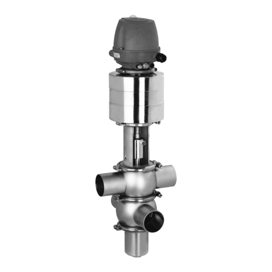
- Page 1 Hygienic valves ® GEA VARIVENT Double-Seat Valve Type R Operating instruction (Translation from the original language) 430BAL008386EN_3...
- Page 2 EU Machinery Directive. This document is protected by copyright. All rights reserved. The document may not, in whole or in part, be copied, reproduced, translated or reduced to an electronic medium of machine-readable form without the express permission of GEA Tuchenhagen GmbH. LEGAL NOTICE Word marks ®...
-
Page 3: Table Of Contents
TABLE OF CONTENTS General Information Information on the Document 1.1.1 Binding Character of These Operating Instructions 1.1.2 Notes on the Illustrations 1.1.3 Symbols and Highlighting Manufacturer address Contact EU Declaration of Conformity in accordance with the EC Machinery Directive 2006/42/EC Translated copy of the EU - Declaration of conformity in accordance with the Pressure Equipment Directive 2006/42/EU Safety... - Page 4 Notes on commissioning Operation and control Safety instructions Cleaning Cleaning 9.1.1 Cleaning Process Examples 9.1.2 Cleaning effect 9.1.3 Cleaning the Leakage Cavity Passivation Maintenance 10.1 Safety instructions 10.2 Inspections 10.2.1 Product contact seals 10.2.2 Pneumatic connections 10.2.3 Electrical connections 10.2.4 Signs on the valve 10.3 Maintenance intervals...
-
Page 5: General Information
General Information Information on the Document General Information Information on the Document The present Operating Instructions are part of the user information for the product. The Operating Instructions contain all the information you need to transport, install, commission, operate and carry out maintenance for the product. 1.1.1 Binding Character of These Operating Instructions These Operating Instructions contain the manufacturer's instructions to the... -
Page 6: Manufacturer Address
Second step in a sequence of operations. ® Result of the previous operation. ® The operation is complete, the goal has been achieved. Hint! Further useful information. Manufacturer address GEA Tuchenhagen GmbH Am Industriepark 2-10 21514 Büchen Contact Tel.:+49 4155 49-0 Fax:+49 4155 49-2035 flowcomponents@gea.com www.gea.com 430BAL008386EN_3 07.02.2022... -
Page 7: Eu Declaration Of Conformity In Accordance With The Ec Machinery Directive 2006/42/Ec
General Information EU Declaration of Conformity in accordance with the EC Machinery Directive 2006/42/EC EU Declaration of Conformity in accordance with the EC Machinery Directive 2006/42/EC 430BAL008386EN_3 07.02.2022... -
Page 8: Translated Copy Of The Eu - Declaration Of Conformity In Accordance With The Pressure Equipment Directive 2006/42/Eu
Translated copy of the EU - Declaration of conformity in accordance with the Pressure Equipment Directive 2006/42/EU Translated copy of the EU - Declaration of conformity in accordance with the Pressure Equipment Directive 2006/42/EU Manufacturer: GEA Tuchenhagen GmbH Am Industriepark 2-10 21514 Büchen We hereby declare that the machine named below... -
Page 9: Safety
The nominal diameters smaller than DN25 are subject to article 4, paragraph 3 of the Pressure Equipment Directive which specifies sound engineering practice. Nominal diameters ≥ IPS 4“; DN 125 valid for the fluid group II. In the event of any deviations, GEA Tuchenhagen GmbH will supply a specific Declaration of Conformity. 2.1.3... -
Page 10: Improper Operating Conditions
Safety Operator’s Duty of Care If these valves are used in areas with a potentially explosive atmosphere, you must absolutely comply with directive 2014/34/EC with respect to all ignition hazards. 2.1.4 Improper operating conditions The operational safety of the component can not be guaranteed under improper operating conditions. -
Page 11: Subsequent Changes
EC Machinery Directive on your own. In general, only original spare parts supplied by GEA Tuchenhagen GmbH should be fitted. This ensures that the component is always operating properly and efficiently. -
Page 12: Environmental Protection
Safety Supplementary Regulations 2.4.2 Environmental Protection Harm to the environment can be avoided by safety-conscious and proactive behaviour of the staff. For environmental protection the following principles apply: • Substances harmful to the environment must not be discharged into the ground or the sewage system. - Page 13 Safety Qualification of personnel Only allow specially trained personnel to carry out work on an explosion- protected system. When working on explosion-protected equipment observe the standards DIN EN 60079-14 for gases and DIN EN 50281-1-2 for dusts. The following minimum qualifications are required: •...
-
Page 14: Safety Equipment
Safety Safety equipment User groups Staff Qualifications Operating personnel Adequate instruction and sound knowledge in the following areas: • Functionality of the component • Operating sequences on the pump • What to do in case of an emergency • Lines of authority and responsibilities with respect to the task Maintenance personnel Appropriate training and a sound knowledge of the structure and functionality of the component. -
Page 15: Residual Dangers
Earthing and short-circuiting. Cover or safeguard any adjacent live parts. Spring tension in the actuator Danger to life caused by compression spring in the actuator. Do not open the actuator but return it to GEA Tuchenhagen for proper disposal. 430BAL008386EN_3 07.02.2022... -
Page 16: Hazard Areas
Safety Hazard Areas Residual dangers on the valve and measures Danger Cause Measure Danger of injury Danger presented by moving or The operator must exercise caution and prudence. sharp-edged parts For all work: • Wear suitable work clothing. • Never operate the machine if the cover panels are not correctly fitted. - Page 17 Safety • On a spring-closing valve there is danger of injury when the clamp connection (43.1) is opened, as the released spring pretension will suddenly lift the actuator. Therefore, release the spring tension before detaching the clamp connection (46) by supplying the actuator (A) with compressed air. •...
-
Page 18: Description
Description Design Description Design Fig.5 Design Designation Actuator T.VIS control top Sealing ring Bearing Sealing disk Bearing disk Lantern Cleaning hood Valve disk 430BAL008386EN_3 07.02.2022... - Page 19 Description Design Design Designation Double-disk Air connection Electrical connection 430BAL008386EN_3 07.02.2022...
-
Page 20: Functional Description
Description Functional description Functional description 3.2.1 Leakage-Proof Shut-Off The upper and the lower valve housing are each equipped with a sealing surface to the valve disks. The chamber between the two valve disks is connected to the open environment by an isolation outlet integrated into the lower valve stem. In the event of seal damage, the leaking fluid can safely flow into the open. - Page 21 Description Identification on the T.VIS control top once the installation (SET-UP) has been completed: • Green steady light (1): valve in non-actuated position • Yellow steady light (1): valve in end position (actuated position) Fig.7 430BAL008386EN_3 07.02.2022...
-
Page 22: Transport And Storage
Transport and storage Storage conditions Transport and storage Storage conditions The valves, valve inserts or spare parts should be stored in a dry place, free of vibrations and dust, and protected from light. To avoid damage, leave the components in their original packaging if possible. If, during transport or storage, the valve is going to be exposed to temperatures ≤... -
Page 23: Scope Of Supply
Transport and storage • Only use approved, fully functional load lifting devices and lifting accessories which are suitable for the intended purpose. Observe the maximum load- bearing capacities. • Secure the valve against slipping. Take the weight of the valve into account and the position of the point of gravity. -
Page 24: Technical Data
Technical data Type plate Technical data Type plate The type plate clearly identifies the valve. GEA Tuchenhagen GmbH Am Industriepark 2-10, 21514 Büchen, Germany Type Serial Mat. Air bar/psi min. max. PSI bar/psi Fig.9 The type plate provides the following key data:... -
Page 25: Cleaning Connection
Technical data Cleaning connection Technical data: Compressed air supply Designation Description Air hose Material PE-LD outside Ø 6 mm - metric Inside Ø 4 mm Material PA outside-Ø 6.35 mm - Inch Inside Ø 4.3 mm Air consumption 2 to 3.8 l for DN 25 to DN 125 (depending on the operating 3.5 to 6.5 l for DN 150 pressure) -
Page 26: Resistance And Permitted Operating Temperature Of The Sealing Materials
The maximum operating temperature is defined by the sealing type and its mechanical load. Due to the versatile conditions of use (e.g. usage duration, switching frequency, type and temperature of product and cleaning agents as well as usage environment), GEA Tuchenhagen recommends that the user carries out resistance tests. Resistance: •... -
Page 27: Pipe Ends - General Table Of Measurements
Technical data Pipe ends - General table of measurements Table of sealing resistance / permitted operating temperature Sealing materials Maximum operating Medium temperatures EPDM HNBR FFKM Product with a fat content of more than 35% – Oils – Table sealing materials - temperature resistance Sealing materials General temperature resistance* -40...+135 °C... -
Page 28: Tool
Technical data Tool Dimensions for Pipes in Inch OD Outside Outside Wall Inside Inch OD diameter acc. diameter thickness diameter to BS 4825 0.5" 12.7 1.65 0.75" 19.05 1.65 15.75 1" 25.4 1.65 22.1 1.5" 38.1 1.65 34.8 2" 50.8 1.65 47.5 2.5"... -
Page 29: Lubricants
Technical data Lubricants List of tools Tool Material no. Installation mandrel DN 65...100, 2.5"...4" 229-109.05 OD/IPS Installation mandrel DN 125, 150, 6" OD / IPS 229-109.06 Manual emergency actuator 221-310.74 Eyebolt 221-104.98 Lubricants Lubricants Material no. Rivolta F.L.G. MD-2 413-071 PARALIQ GTE 703 413-064 Weights... -
Page 30: Assembly And Installation
Assembly and installation Safety instructions Assembly and installation Safety instructions Hazardous situations during installation can be avoided by safety-conscious and proactive behaviour of the personnel. For installation, the following principles apply: • Only qualified personnel are allowed to set-up, install and commission the component. -
Page 31: Valve With Welded Ends
Assembly and installation Valve with welded ends Carry out the following steps: Fit valves with detachable pipe connection elements – using suitable connection fittings – directly into the pipe system. ® Valve is installed. Valve with welded ends This section describes the welding procedure for the valve housing. Warning! Spring tension in the valve Danger of injury when opening the clamp connections on the actuator or on... -
Page 32: Pneumatic Connections
Assembly and installation Pneumatic connections Hint! Welding method: We recommend using the automatic orbital welding method. All welding work should only be performed by certified welders or machine operators (orbital welders). Housing-O-rings: When assembling the valve always replace the housing O-rings to ensure that the valve is tight. Pneumatic connections 6.6.1 Air Requirement... -
Page 33: Electrical Connection With T.vis Control Top
Assembly and installation Electrical connection with T.VIS control top Use the hose cutter to cut the pneumatic hoses square. Push the air hose into the air connector on the control top. Re-open the compressed air supply. ® Done Electrical connection with T.VIS control top Danger Live parts Electrical shock can result in serious personal injury or death. -
Page 34: Start-Up
Start-up Safety instructions Start-up Safety instructions Initial commissioning For initial commissioning, the following principles apply: • Take protective measures against dangerous contact voltages in accordance with pertinent regulations. • The valve must be completely assembled and correctly adjusted. All screw connections must be securely tightened. -
Page 35: Operation And Control
Operation and control Safety instructions Operation and control Safety instructions Dangerous situations during operation can be avoided by safety-conscious and proactive behaviour of the personnel. For operation, the following principles apply: • Monitor the component during operation. • Safety devices must not be changed, removed or taken out of service. Check all safety devices at regular intervals. -
Page 36: Cleaning
Cleaning Cleaning Cleaning Cleaning All parts in contact with product must be cleaned at regular intervals. Always observe the safety data sheets issued by the cleaning agent manufacturers. Only use cleaning agents which do not cause damage to the seals and the inner parts of the valve. -
Page 37: Cleaning The Leakage Cavity
Cleaning Passivation 9.1.3 Cleaning the Leakage Cavity Cleaning of the leakage cavity is performed using a spray nozzle in the double disk that is connected to a valve seat cleaning pipe. Here, there can only be general recommendations made as to how many and the length of the spray cleaning, which are all dependent on the conditions occurring at each facility, such as type of products, temperatures, cleaning means, cleaning intervals, etc., which could require more frequent or longer spray cleaning. -
Page 38: Maintenance
Maintenance Safety instructions Maintenance 10.1 Safety instructions Maintenance and repair Before carrying out maintenance and repair work on the component's electrical equipment, perform the following steps in accordance with the "5 safety rules": • Isolate from the power supply • Take appropriate measures to prevent switch on •... -
Page 39: Inspections
Maintenance Inspections • Disconnect all power and utility lines. • Markings, e.g. on lines, must not be removed. • Do not climb on the component. Use suitable access aids and working platforms. • Mark the lines (if unmarked) prior to disassembly to ensure they are not confused when re-assembling. -
Page 40: Signs On The Valve
Maintenance Maintenance intervals ® Done Hint! The electrical cable must be long enough to allow the control top to be removed via the switch bar. 10.2.4 Signs on the valve Carry out the following steps: Check the signs on the valve. Replace damaged or missing stickers with new ones. -
Page 41: Disassembly
Maintenance Disassembly Shut off the control air supply. Disconnect the power supply. Take the valve out of the pipe section, with all housings and housing connections if possible. ® Done 10.5 Disassembly 10.5.1 Start disassembly Requirement: • No solenoid valve must be actuated electrically. If required, operate the pilot valve with manual override. -
Page 42: Removing The Control Top
Maintenance Disassembly Unscrew the cleaning hose (30). Vent actuator at (22) or control the pilot valve using the manual override. Fig.11: S = manual override pilot valve Remove the clamp connection (43.1) between housing and lantern. Vent the actuator. ® Done 10.5.2 Removing the control top... - Page 43 Maintenance Disassembly Fig.12 Requirement: • No solenoid valve must be actuated electrically. If required, operate the pilot valve with manual override. • The pneumatic and electrical connections on the plant side can remain on the control top. Caution! The switch bar is sensitive and must be protected from impact stress.
-
Page 44: Disconnecting The Valve From The Housing
Maintenance Disassembly Pull the control top (B) upwards. Remove switch bar. ® Done 10.5.3 Disconnecting the Valve from the Housing Fig.13 Notice Sensitive parts The surfaces of the balancers are sealing surfaces and must not be damaged. ► When removing the valve from the pipe take care not to hit the balancer against the housing. -
Page 45: Disassembly Balancer Plug
Maintenance Disassembly Fig.14 Carry out the following steps: Grip actuator (A) with belt wrench and separate the valve disk (15) from the actuator (A) at the width across flats (C). Remove the clamp connection (43) between the lantern and the actuator (A) and remove the lantern. -
Page 46: Disassembly Of The Housing Combination
Maintenance Installation Carry out the following steps: Remove the clamp connection (46) between the housing (402) and the balancer plug (92). Remove the balancer plug (92), seal ring RA (65) is accessible. ® Done 10.5.6 Disassembly of the housing combination If available, disassemble the housing combination for housings that are not welded. - Page 47 Maintenance Installation Carefully insert the rod guide strip (2) of the bearing plug into the cleaning hood (11). Screw the cleaning hood (11) on the spanner flat (D9 onto the valve disk (15) at the spanner flat (C). Fig.16 430BAL008386EN_3 07.02.2022...
-
Page 48: Fitting The Control Top
Maintenance Installation Fig.17 Assembly the lantern (9) with hinged clamp on the actuator (A). Screw the valve disk (15), spanner flat C into the actuator (A). Hold the actuator with a belt wrench. Screw the switch bar into the actuator. ®... -
Page 49: Assembly Of The Housing Combination
Maintenance Installation Fig.18 Caution! The switch bar is sensitive and must be protected from impact stress. Damage to switch bar. ► Protect the switch bar against impact stress. Carry out the following steps: Put on the control top (B) from the top. Attach the pneumatic connection from the actuator. -
Page 50: Assembly Balancer Plug
Maintenance Installation Fig.19: Seat ring with marked installation direction Mount the clamp connection (43) between housings. ® Housing combination is assembled. 10.6.5 Assembly balancer plug Fig.20 Before assembly apply a very thin layer of grease to the balancer plug (92). Align the valve insert and let is slide into the housing. - Page 51 Maintenance Installation Tighten the valve disk (15) and the balancer plug (92) with the correct torque, see Section 10.6.1, Page 46. 430BAL008386EN_3 07.02.2022...
-
Page 52: Installing The Valve Insert In The Housing
Maintenance Installation 10.6.6 Installing the valve insert in the housing Fig.21 Requirement: • No solenoid valve must be actuated electrically. If required, operate the pilot valve with manual override. • The pneumatic and electrical connections on the plant side can remain on the control top. -
Page 53: Checking The Function
Maintenance Installation Fig.22 Actuate the main stroke with the manual override (Y1) so that the valve insert moves into the mousing under its own weight. Fig.23 Mount the clamp connection (43.1) between housing and lantern. ! Ensure that the clamp connection (43.1) is mounted correctly. Aerate the actuator at (Y1). -
Page 54: Maintenance
Maintenance Maintenance Please take the operating instructions for the respective control top into account for adjustment of the feedbacks. ® Stroke has been checked. Strokes depending on size Valve stroke Valve size Valve stroke [mm] Metric Inch OD 1.5" 2" 30.5 2.5"... -
Page 55: Replacing Seals
Maintenance Maintenance Notice Damage to the valve Damage to these parts can result in malfunction. ► Observe the safety information sheets issued by the detergent manufacturers! ► Only use detergents which are non-abrasive and not aggressive towards stainless steel. ► Use only cleaning mediums which do not damage the materials of the control top (PPE, PA). - Page 56 Maintenance Maintenance Caution! Danger of injury! The pickset tool can slip off when the V-ring is removed ► Clamp the valve disk in the vice using vice supports Hint! Functional and running surfaces of the valve disks must not get damaged.
-
Page 57: 10.7.2.2 Replacing V-Ring Ra Valve Disk
Maintenance Maintenance Fig.28 Insert the V-ring evenly. ! Check that the V-ring is evenly and correctly inserted. ® Done Hint! Used seals must not be used again, since the proper function of the seal can then no longer be ensured. 10.7.2.2 Replacing V-Ring RA valve disk Hint! Replace defective seals, but always fit new housing O-rings to ensure... -
Page 58: 10.7.2.3 Replace More Seals
Maintenance Maintenance Before fitting, wet V-ring RA on the side not in contact with product (rear side). Pay attention that water does not drip into the V-ring groove on the valve disc. Put in V-ring RA. ! Make sure the installation position of V-ring RA is correct (see illustration). Fig.30 Use the insertion tool to press in the V-ring RA –... -
Page 59: Lubricating Seals And Threads
Maintenance Maintenance Fig.32 For nominal widths up to DN 50 or 2”, different seals may be required. For further details and small nominal width please refer to the spare parts list. 10.7.3 Lubricating seals and threads Caution! Damage to seals and threads Stainless steel threads tend to seize and cold weld and must be greased. - Page 60 Rivolta F.L.G. MD-2 can be ordered from GEA Tuchenhagen. Using other types of grease can result in malfunctions or in premature seal failure.
-
Page 61: Alarms
Alarms Malfunctions and remedies Alarms 11.1 Malfunctions and remedies In the event of malfunctions immediately deactivate the valve and secure it against inadvertent reactivation. Malfunctions may only be remedied by qualified staff, who must observe the safety precautions. Fault Cause Remedy Check the system Fault in the controller... -
Page 62: Decommissioning
► Never open the actuator. ► GEA Tuchenhagen accepts unopened actuators and arranges for proper disposal free of charge. Carry out the following steps: Remove the actuator. Pack the actuator safely and send it to GEA Tuchenhagen GmbH. ® Done 430BAL008386EN_3 07.02.2022... -
Page 63: Spare Parts List - Double Seat Valve R
Spare parts list - Double seat valve R Spare parts list - Double seat valve R Fig.33 Fig.34 430BAL008386EN_3 07.02.2022... - Page 64 Spare parts list - Double seat valve R Item Designation Material DN 25 DN 40 DN 50 DN 65 Sealing set complete 1) EPDM 221-528.74 221-511.32 221-511.32 221-001693 221-001424 221-519.11 221-519.11 221-001695 HNBR 221-004163 221-000752 221-000752 221-004165 Seal ring EPDM 924-084 924-084 924-084...
- Page 65 Spare parts list - Double seat valve R Item Designation Material DN 25 DN 40 DN 50 DN 65 Locking ring 1.4301 221-143.01 Clamp join KL 1.4401 221-507.02 221-507.04 221-507.04 221-507.09 Clamp join KL 1.4401 221-507.06 221-507.06 221-507.06 221-507.06 Seal ring EPDM 924-084 924-305...
- Page 66 Spare parts list - Double seat valve R Item Designation Material DN 80 DN 100 DN 125 DN 150 Sealing set complete 1) EPDM 221-001693 221-001687 221-001689 221-001692 221-001695 221-001688 221-001690 221-001691 HNBR 221-004165 221-004166 Seal ring EPDM 924-085 924-085 924-088 924-088 924-083...
- Page 67 Spare parts list - Double seat valve R Item Designation Material DN 80 DN 100 DN 125 DN 150 Locking ring 1.4301 Clamp join KL 1.4401 221-507.09 221-507.11 221-507.13 221-507.14 Clamp join KL 1.4401 221-507.06 221-507.06 221-507.11 221-507.11 Seal ring EPDM 221-367.03 221-367.04...
- Page 68 Spare parts list - Double seat valve R Item Designation Material 1" OD 1.5" OD 2" OD 2.5" OD Sealing set complete 1) EPDM 221-528.74 221-511.32 221-511.32 221-001693 221-001424 221-519.11 221-519.11 221-001695 HNBR 221-004163 221-000752 221-000752 221-004165 Seal ring EPDM 924-084 924-084 924-084...
- Page 69 Spare parts list - Double seat valve R Item Designation Material 1"OD 1.5"OD 2" OD 2.5" OD Locking ring 1.4301 221-143.01 Clamp join KL 1.4401 221-507.02 221-507.04 221-507.04 221-507.09 Clamp join KL 1.4401 221-507.06 221-507.06 221-507.06 221-507.06 Seal ring EPDM 924-084 924-305 924-305...
- Page 70 Spare parts list - Double seat valve R Item Designation Material 3" OD 4" OD 6" OD Sealing set complete 1) EPDM 221-001693 221-001687 221-001692 221-001695 221-001688 221-001691 HNBR 221-004165 221-004166 Seal ring EPDM 924-085 924-085 924-088 924-083 924-083 924-087 HNBR 924-313 924-313...
- Page 71 Spare parts list - Double seat valve R Item Designation Material 3" OD 4" OD 6" OD Locking ring 1.4301 Clamp join KL 1.4401 221-507.09 221-507.11 221-507.14 Clamp join KL 1.4401 221-507.06 221-507.06 221-507.11 Seal ring EPDM 221-367.03 221-367.04 221-367.06 221-367.08 221-367.09 221-367.11...
- Page 72 Spare parts list - Double seat valve R Item Designation Material 2" IPS 3" IPS 4" IPS 6" IPS Sealing set complete 1) EPDM 221-511.32 221-001693 221-001687 221-001692 221-519.11 221-001695 221-001688 221-001691 HNBR 221-000752 221-004165 221-004166 Seal ring EPDM 924-084 924-085 924-085 924-088...
- Page 73 Spare parts list - Double seat valve R Item Designation Material 2" IPS 3" IPS 4" IPS 6" IPS Locking ring 1.4301 Clamp join KL 1.4401 221-507.04 221-507.03 221-507.11 221-507.14 Clamp join KL 1.4401 221-507.06 221-507.09 221-507.06 221-507.11 Seal ring EPDM 924-305 221-367.03...
- Page 74 Spare parts list - Double seat valve R Sealing sets for VARIVENT® double seat valve R DN 25 DN 40/50 DN 65/80 DN 100 DN 150 Item Designation Material DN 125 1" 1.5"/2" 2.5"/3" 4" 6" Seal ring EPDM 924-084 924-084 924-085 924-085...
-
Page 75: Dimension Sheet - Varivent® Double Seat Valve R
Dimension sheet - VARIVENT® double seat valve R Dimension sheet - VARIVENT® double seat valve R Fig.35 430BAL008386EN_3 07.02.2022... - Page 76 Dimension sheet - VARIVENT® double seat valve R Nominal Actuato Pipe Housing Size Valve width Expansion Stroke Ø Weight [mm] [mm] [mm] [mm] [mm] [mm] [mm] [kg] [mm] [mm] DN 25 29.0 × 1.50 50.0 91.0 329.0 458.0 DN 40 41.0 ×...
-
Page 77: Appendix
Appendix Lists Appendix 15.1 Lists 15.1.1 Abbreviations and terms Abbreviation Explanation British Standard Unit of measurement of pressure [bar] All pressure data expressed in [bar/psi] is assumed to be gauge pressure [barg/psig] unless explicitly specified otherwise. approx. approximately °C Unit of measurement of temperature [degree Celsius] Unit of measurement of volume [cubic decimetre] standard volume (standard litres) DIN nominal width... - Page 78 Appendix Abbreviation Explanation Metric Unit of measurement of work [newton metre] TORQUE SPECIFICATION: 1 Nm = 0.737 lbft Pound-Force (lb) + Feet (ft) Polyamide PE-LD Low-density polyethylene Polytetrafluoroethylene Anglo-American unit of measurement for pressure [pound- force per square inch] All pressure data expressed in [bar/psi] is assumed to be gauge pressure [barg/psig] unless explicitly specified otherwise.
- Page 79 Appendix 430BAL008386EN_3 07.02.2022...
Need help?
Do you have a question about the VARIVENT DN 25 and is the answer not in the manual?
Questions and answers