GEA VARIVENT K Operating Instruction
Hygienic valves
Hide thumbs
Also See for VARIVENT K:
- Operating instructions manual (36 pages) ,
- Operating instructions manual (34 pages)

Related Manuals for GEA VARIVENT K


Summary of Contents for GEA VARIVENT K
- Page 1 Hygienic valves ® GEA VARIVENT valve type K Operating instruction (Translation from the original language) 430BAL008372EN_4...
- Page 2 EU Machinery Directive. This document is protected by copyright. All rights reserved. The document may not, in whole or in part, be copied, reproduced, translated or reduced to an electronic medium of machine-readable form without the express permission of GEA Tuchenhagen GmbH. LEGAL NOTICE Word marks ®...
-
Page 3: Table Of Contents
TABLE OF CONTENTS General Information Information on the Document 1.1.1 Binding Character of These Operating Instructions 1.1.2 Notes on the Illustrations 1.1.3 Symbols and Highlighting Manufacturer address Contact EU Declaration of Conformity in accordance with the EC Machinery Directive 2006/42/EC Translated copy of the EU - Declaration of conformity in accordance with the Pressure Equipment Directive 2006/42/EU Safety... - Page 4 Safety instructions Cleaning Cleaning 9.1.1 Cleaning Process Examples 9.1.2 Cleaning effect 9.1.3 Cleaning the Leakage Cavity Passivation Maintenance 10.1 Safety instructions 10.2 Inspections 10.2.1 Product contact seals 10.2.2 Pneumatic connections 10.2.3 Electrical connections 10.3 Maintenance intervals 10.4 Prior to disassembly 10.5 Disassembling the Valve 10.5.1...
-
Page 5: General Information
General Information Information on the Document General Information Information on the Document The present Operating Instructions are part of the user information for the product. The Operating Instructions contain all the information you need to transport, install, commission, operate and carry out maintenance for the product. 1.1.1 Binding Character of These Operating Instructions These Operating Instructions contain the manufacturer's instructions to the... -
Page 6: Manufacturer Address
Second step in a sequence of operations. ® Result of the previous operation. ® The operation is complete, the goal has been achieved. Hint! Further useful information. Manufacturer address GEA Tuchenhagen GmbH Am Industriepark 2-10 21514 Büchen Contact Tel.:+49 4155 49-0 Fax:+49 4155 49-2035 flowcomponents@gea.com www.gea.com 430BAL008372EN_4 11.03.2022... -
Page 7: Eu Declaration Of Conformity In Accordance With The Ec Machinery Directive 2006/42/Ec
General Information EU Declaration of Conformity in accordance with the EC Machinery Directive 2006/42/EC EU Declaration of Conformity in accordance with the EC Machinery Directive 2006/42/EC 430BAL008372EN_4 11.03.2022... -
Page 8: Translated Copy Of The Eu - Declaration Of Conformity In Accordance With The Pressure Equipment Directive 2006/42/Eu
Translated copy of the EU - Declaration of conformity in accordance with the Pressure Equipment Directive 2006/42/EU Translated copy of the EU - Declaration of conformity in accordance with the Pressure Equipment Directive 2006/42/EU Manufacturer: GEA Tuchenhagen GmbH Am Industriepark 2-10 21514 Büchen We hereby declare that the machine named below... -
Page 9: Safety
Pressure Equipment Directive which specifies sound engineering practice. Nominal diameters ≥ IPS 4“; DN 125 valid for the fluid group II. In the event of any deviations, GEA Tuchenhagen GmbH will supply a specific Declaration of Conformity. 2.1.3... -
Page 10: Improper Operating Conditions
Safety Operator’s Duty of Care Refer to and observe the additional operating instructions “ATEX version valves”. For details regarding the marking of valves for potentially hazardous areas also refer to the additional operating instructions “ATEX version valves”. If these valves are used in areas with a potentially explosive atmosphere, you must absolutely comply with directive 2014/34/EC with respect to all ignition hazards. -
Page 11: Subsequent Changes
EC Machinery Directive on your own. In general, only original spare parts supplied by GEA Tuchenhagen GmbH should be fitted. This ensures the reliable and economical operation of the valve. -
Page 12: Environmental Protection
Safety Supplementary Regulations 2.4.2 Environmental Protection Harm to the environment can be avoided by safety-conscious and proactive behaviour of the staff. For environmental protection the following principles apply: • Substances harmful to the environment must not be discharged into the ground or the sewage system. - Page 13 Safety Qualification of Staff Only allow specially trained staff to carry out any work on explosion-protected equipment. When working on explosion-protected equipment observe the standards DIN EN 60079-14 for gases and DIN EN 50281-1-2 for dusts. The following minimum qualifications are required: •...
-
Page 14: Safety Equipment
Safety Safety equipment User groups Staff Qualifications Operating staff Adequate instruction and sound knowledge in the following areas: • Function of the valve • Valve operating sequences • What to do in case of an emergency • Lines of authority and responsibilities with respect to the task Maintenance staff Adequate instruction as well as sound knowledge of the design and function of the valve. -
Page 15: Residual Dangers
Earthing and short-circuiting. Cover or safeguard any adjacent live parts. Spring tension in the actuator Danger to life caused by compression spring in the actuator. Do not open the actuator but return it to GEA Tuchenhagen for proper disposal. 430BAL008372EN_4 11.03.2022... -
Page 16: Hazard Areas
Safety Hazard Areas Residual dangers on the valve and measures Danger Cause Measure Danger of injury Danger presented by moving or The operator must exercise caution and prudence. sharp-edged parts For all work: • Wear suitable work clothing. • Never operate the machine if the cover panels are not correctly fitted. - Page 17 Safety detaching the clamp connections (43, 46) by supplying the actuator (A) with compressed air. • Before starting any maintenance, servicing or repair work, disconnect the valve from the power supply and secure it against inadvertently being switched back on again. •...
-
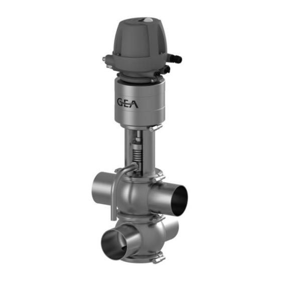
Page 18: Description
Description Design Description Design Fig.5 Design Designation Actuator Control top Seal ring Bearing Seal disk Bearing disc Lantern Spring plate Valve disk Double-disk 430BAL008372EN_4 11.03.2022... - Page 19 Description Design Design Designation Compression spring Air connection Electrical connection Leakage pipe Valve housing 430BAL008372EN_4 11.03.2022...
-
Page 20: Functional Description
Description Functional description Functional description 3.2.1 Actuator Function The actuator is of the spring-closing type (Z). The valve is closed in the non- actuated position. Identification on the T.VIS control top once the installation (SET-UP) has been completed: • Green steady light (1): valve in non-actuated position •... -
Page 21: Transport And Storage
Transport and storage Storage conditions Transport and storage Storage conditions The valves, valve inserts or spare parts should be stored in a dry place, free of vibrations and dust, and protected from light. To avoid damage, leave the components in their original packaging if possible. If, during transport or storage, the valve is going to be exposed to temperatures ≤... -
Page 22: Scope Of Supply
Transport and storage • Only use approved, fully functional load lifting devices and lifting accessories which are suitable for the intended purpose. Observe the maximum load- bearing capacities. • Secure the valve against slipping. Take the weight of the valve into account and the position of the point of gravity. -
Page 23: Technical Data
Technical data Type plate Technical data Type plate The type plate clearly identifies the valve. Fig.8 The type plate provides the following key data: Key data of the valve Type Double seat valve K Serial Serial number Material 1.4404(AISI316L)/FKM (FDA) Control air pressure bar/psi min. -
Page 24: Resistance And Permitted Operating Temperature Of The Sealing Materials
The maximum operating temperature is defined by the sealing type and its mechanical load. Due to the versatile conditions of use (e.g. usage duration, switching frequency, type and temperature of product and cleaning agents as well as usage environment), GEA Tuchenhagen recommends that the user carries out resistance tests. 430BAL008372EN_4 11.03.2022... - Page 25 Technical data Resistance and permitted operating temperature of the sealing materials Resistance: • + = good resistance • o = reduced resistance • – = no resistance Table of sealing resistance / permitted operating temperature Maximum Sealing material Medium operating EPDM HNBR temperatures...
-
Page 26: Pipe Ends - General Table Of Measurements
Technical data Pipe ends - General table of measurements Sealing materials General temperature resistance* -25...+140 °C HNBR (-13...+284 °F) * The general resistance of the material does not correspond to the maximum operating temperature. Pipe ends - General table of measurements Hint! Not every valve is available in every size. -
Page 27: Dimensions Leakage Pipe
Technical data Dimensions leakage pipe Dimensions for tubes in Inch IPS Outside diameter Outside Wall Inside Inch IPS according to diameter thickness diameter DIN EN ISO 1127 2" 60.3 56.3 3" 88.9 84.3 4" 114.3 109.7 6" 168.3 2.77 162.76 Dimensions leakage pipe Leakage pipe 90°... -
Page 28: Lubricants
Technical data Lubricants Lubricants Lubricants Material no. Rivolta F.L.G. MD-2 (1 kg tin) 413-071 Rivolta F.L.G. MD-2 (100g tube) 413-136 Weights Size Weight [kg] DN 25 DN 40 DN50 DN 65 DN 80 DN 100 DN 125 DN 150 OD 1" OD 1.5"... -
Page 29: Assembly And Installation
Assembly and installation Safety instructions Assembly and installation Safety instructions Dangerous situations during assembly can be avoided by safety-conscious and proactive behaviour of the staff. For installation, the following principles apply: • Only properly qualified staff is allowed to install, assemble and set the valve into operation. -
Page 30: Valve With Welded Ends
Assembly and installation Valve with Welded Ends Caution! Liquids in pipes Danger of injury due to liquid spraying out ► Therefore, before releasing any pipe connections or hinged clamps: drain the pipe and, if necessary, clean or rinse it. ► Separate the pipe section in which the valve is to be fitted from the rest of the piping system to prevent product entering again. -
Page 31: Pneumatic Connections
Assembly and installation Pneumatic connections Fit the seals. ® The valve disk is lowered. ® Install the valve with welded ends. Hint! Welding method: We recommend using the automatic orbital welding method. All welding work should only be performed by certified welders or machine operators (orbital welders). -
Page 32: Electrical Connection With T.vis Control Top
Assembly and installation Electrical connection with T.VIS control top • A hose cutter Carry out the following steps: Shut off the compressed air supply. Use the hose cutter to cut the pneumatic hoses square. Push the air hose into the air connector on the control top. Re-open the compressed air supply. -
Page 33: Start-Up
Start-up Safety instructions Start-up Safety instructions Initial commissioning For initial commissioning, the following principles apply: • Take protective measures against dangerous contact voltages in accordance with pertinent regulations. • The valve must be completely assembled and correctly adjusted. All screw connections must be securely tightened. -
Page 34: Operation And Control
Operation and control Safety instructions Operation and control Safety instructions Dangerous situations during operation can be avoided by safety-conscious and proactive behaviour of the staff. For operation, the following principles apply: • Monitor the valve during the operation. • Safety devices must not be changed, removed or taken out of service. Check all safety devices at regular intervals. -
Page 35: Cleaning
Cleaning Cleaning Cleaning Cleaning All parts in contact with product must be cleaned at regular intervals. Always observe the safety data sheets issued by the cleaning agent manufacturers. Only use cleaning agents which do not cause damage to the seals and the inner parts of the valve. -
Page 36: Cleaning The Leakage Cavity
Cleaning Passivation 9.1.3 Cleaning the Leakage Cavity Cleaning the leakage chamber of the double seat valve type K is not possible. This valve is therefore primarily used in the CIP and gas area. The switching leaks are discharged via the leakage pipe in the lantern. Passivation Before commissioning a plant, passivation is commonly carried out for long pipes and tanks. -
Page 37: Maintenance
Maintenance Safety instructions Maintenance 10.1 Safety instructions Maintenance and repair Before starting any maintenance and repair work on the electrical devices of the valve, carry out the following steps in accordance with the "5 safety rules": • Isolate from the power supply •... -
Page 38: Inspections
Maintenance Inspections • Do not climb on the valve. Use suitable access aids and working platforms. • Mark the lines (if unmarked) prior to disassembly to ensure they are not confused when re-assembling. • Protect open line ends with blind plugs against ingress of dirt. •... -
Page 39: Maintenance Intervals
Maintenance Maintenance intervals Hint! The electrical cable must be long enough to allow the control top to be removed via the switch bar. 10.3 Maintenance intervals To ensure the highest operational reliability of the magnetic separator, all wearing parts should be replaced at longer intervals. The actual maintenance intervals can only be determined by the user since they depend on the operating conditions, for instance: •... -
Page 40: Removing The Valve Insert
Maintenance Disassembling the Valve 10.5.1 Removing the Valve Insert Fig.9 Fig.10 Requirement: • No solenoid valve must be actuated electrically or manually. • The pneumatic and electrical connections on the plant side can remain on the control top. • During maintenance and servicing work no process must be in operation in the area concerned. -
Page 41: Separating The Valve From The Actuator
Maintenance Disassembling the Valve • If possible, take the valve out of the pipe section, with all housings and housing connections Notice The permanent magnet on the switch bar is fragile. Damage to the permanent magnet. ► Protect the permanent magnet against impact stress. Warning! Spring tension in the valve Danger of injury when detaching the clamp connections (43, 46) as the... - Page 42 Maintenance Disassembling the Valve Fig.11 Fig.12 Notice Sensitive valve parts Damage to valve parts. ► Protect the valve parts against impact stress. Carry out the following steps: Unscrew the hexagon nuts (38) and leakage pipe (37). Remove the clamp connection (46) between drive and lamp. 430BAL008372EN_4 11.03.2022...
-
Page 43: Maintenance
Maintenance Maintenance Secure actuator (A) with a strap wrench. Place the jaw wrench onto the spanner surface of the valve disk (15) and remove the actuator. Pull the valve insert out of the lantern. ! The bearing disc (4) and the seal disks (3) must not hit the rod (16) of double disk when the valve insert is withdrawn. -
Page 44: Replacing Seals
Maintenance Maintenance Notice Damage to the valve Damage to these parts can result in malfunction. ► Observe the safety information sheets issued by the detergent manufacturers! ► Only use detergents which are non-abrasive and not aggressive towards stainless steel. Carry out the following steps: Disassemble the valve, see Section 10.5, Page 39. -
Page 45: Lubricating Seals And Threads
Maintenance Maintenance Fig.15 Before fitting, wet the V-ring on the side not in contact with product (rear side). Pay attention that water does not drip into the V-ring groove on the valve disk. Air out the valve upon connection (22). Put in the V-ring. -
Page 46: Installation
Rivolta F.L.G. MD-2 can be ordered from GEA Tuchenhagen. Using other types of grease can result in malfunctions or in premature seal failure. -
Page 47: Guide Rings
Maintenance Installation Mount the O-ring (25) using the installation mandrel. 10.7.2 Guide rings Fig.19 After installing the double disk (16) and the leakage outlet (14), push the guide ring (21) through the opening in the leakage outlet and install. 10.7.3 Spring Fig.20 Before the spring is placed into the cleaning hood, both surface ends must be... -
Page 48: Strokes Depending On Size
Maintenance Installation Torques [Nm] [lbft] Clamps on the control top Clamp connection cast half rings Clamp connection 16.2 cast half rings Cast clamps 10.7.6 Strokes depending on size Setting the valve stroke Carry out the following steps: Actuate the valve with compressed air. Check the stroke of the valve in accordance with (Page 48). - Page 49 Maintenance Valve Stroke Valve size Valve stroke [mm] 2" 3" 4" 6" 430BAL008372EN_4 11.03.2022...
-
Page 50: Alarms
Alarms Malfunctions and remedies Alarms 11.1 Malfunctions and remedies In the event of malfunctions immediately deactivate the valve and secure it against inadvertent reactivation. Malfunctions may only be remedied by qualified staff, who must observe the safety precautions. Malfunction Cause Remedy Check the system Fault in the controller... -
Page 51: Decommissioning
► Never open the actuator. ► GEA Tuchenhagen accepts unopened actuators and arranges for proper disposal free of charge. Carry out the following steps: Remove the actuator. Pack the actuator safely and send it to GEA Tuchenhagen GmbH. ® Done 430BAL008372EN_4 11.03.2022... -
Page 52: Spare Parts List - Mixproof Valve K
Spare parts list - mixproof valve K Spare parts list - mixproof valve K Fig.21 Fig.22 430BAL008372EN_4 11.03.2022... - Page 53 Spare parts list - mixproof valve K Item Designation Material DN 25 DN 40 DN 50 DN 65 Sealing set complete 1) EPDM 221-304.12 221-304.13 221-304.13 221-304.14 221-519.32 221-519.33 221-519.33 221-519.34 HNBR 221-519.75 221-519.76 221-519.76 221-519.77 Seal ring EPDM 924-084 924-084 924-084 924-085...
- Page 54 Spare parts list - mixproof valve K Item Designation Material DN 25 DN 40 DN 50 DN 65 Clamp join KL 1.4401 221-507.02 221-507.04 221-507.04 221-507.09 Clamp join KL 1.4401 221-507.06 221-507.06 221-507.06 221-507.06 Housing V1 1.4404 221-101.19 221-101.21 221-101.22 221-101.05 Housing V2 1.4404...
- Page 55 Spare parts list - mixproof valve K Item Designation Material DN 80 DN 100 DN 125 DN 150 Sealing set complete 1) EPDM 221-304.14 221-304.15 221-304.10 221-304.11 221-519.34 221-519.35 221-519.04 221-519.05 HNBR 221-519.77 221-004176 Seal ring EPDM 924-085 924-085 924-088 924-088 924-083 924-083...
- Page 56 Spare parts list - mixproof valve K Item Designation Material DN 80 DN 100 DN 125 DN 150 Clamp join KL 1.4401 221-507.09 221-507.11 221-507.13 221-507.14 Clamp join KL 1.4401 221-507.06 221-507.06 221-507.11 221-507.11 Housing V1 1.4404 221-101.06 221-101.07 221-101.18 221-101.66 Housing V2 1.4404...
- Page 57 Spare parts list - mixproof valve K Item Designation Material 1" OD 1.5" OD 2" OD 2.5" OD Sealing set complete 1) EPDM 221-304.12 221-304.03 221-304.13 221-304.14 221-519.32 221-519.33 221-519.33 221-519.34 HNBR 221-519.75 221-519.76 221-519.76 221-519.77 Seal ring EPDM 924-084 924-084 924-084 924-085...
- Page 58 Spare parts list - mixproof valve K Item Designation Material 1"OD 1.5"OD 2" OD 2.5" OD Clamp join KL 1.4401 221-507.02 221-507.04 221-507.04 221-507.09 Clamp join KL 1.4401 221-507.06 221-507.06 221-507.06 221-507.06 Housing V1 1.4404 221-101.27 221-101.28 221-101.29 221-101.30 Housing V2 1.4404 221-102.52 221-102.53...
- Page 59 Spare parts list - mixproof valve K Item Designation Material 3" OD 4" OD 6" OD Sealing set complete 1) EPDM 221-304.14 221-304.15 221-304.17 221-519.34 221-519.35 221-519.37 HNBR 221-519.77 221-004176 Seal ring EPDM 924-085 924-085 924-088 924-083 924-083 924-087 HNBR 924-313 924-313 Bearing...
- Page 60 Spare parts list - mixproof valve K Item Designation Material 3" OD 4" OD 6" OD Clamp join KL 1.4401 221-507.09 221-507.11 221-507.14 Clamp join KL 1.4401 221-507.06 221-507.06 221-507.11 Housing V1 1.4404 221-101.31 221-101.32 221-101.72 Housing V2 1.4404 221-102.56 221-102.57 221-102.58 Housing KL...
- Page 61 Spare parts list - mixproof valve K Item Designation Material 2" IPS 3" IPS 4" IPS 6" IPS Sealing set complete 1) EPDM 221-304.13 221-304.14 221-304.15 221-304.17 221-519.33 221-519.34 221-519.35 221-519.37 HNBR 221-519.76 221-519.77 221-004176 Seal ring EPDM 924-084 924-085 924-085 924-088 924-082...
- Page 62 Spare parts list - mixproof valve K Item Designation Material 2" IPS 3" IPS 4" IPS 6" IPS Clamp join KL 1.4401 221-507.04 221-507.03 221-507.11 221-507.14 Clamp join KL 1.4401 221-507.06 221-507.09 221-507.06 221-507.11 Housing V1 1.4404 221-101.37 221-101.35 221-101.36 221-101.17 Housing V2 1.4404...
- Page 63 Spare parts list - mixproof valve K sealing sets for VARIVENT® mixproof valve K DN 25 DN 40/50 DN 65/80 DN 100 DN 150 Item Designation Material DN 125 1" 1.5"/2" 2.5"/3" 4" 6" Seal ring Ø EPDM 924-084 924-084 924-085 924-085 924-088...
-
Page 64: Dimension Sheet - Varivent ® Double Seat Valve K
® Dimension Sheet - VARIVENT Double Seat Valve K ® Dimension Sheet - VARIVENT Double Seat Valve K Fig.23 430BAL008372EN_4 11.03.2022... - Page 65 ® Dimension Sheet - VARIVENT Double Seat Valve K Nominal Tube Housing Actuator Dimension Valve Width Expansion Ø Stroke S Weight [mm] [mm] [mm] [mm] [mm] [mm] [mm] [mm] [kg] [mm] DN 25 29.0 x 1.50 50.0 58.0 329.0 458.0 DN 40 41.0 x 1.50 62.0...
-
Page 66: Appendix
Appendix Lists Appendix 15.1 Lists 15.1.1 Abbreviations and terms Abbreviation Explanation British Standard Unit of measurement of pressure [bar] All pressure data expressed in [bar/psi] is assumed to be gauge pressure [barg/psig] unless explicitly specified otherwise. approx. approximately °C Unit of measurement of temperature [degree Celsius] Unit of measurement of volume [cubic decimetre] Standard volume (standard litre) DIN nominal width... - Page 67 Appendix Abbreviation Explanation Metric Unit of measurement of work [newton metre] Specification of torque 1 Nm = 0.737 lbft Pound-Force (lb) + Feet (ft) Polyamide PE-LD Low-density polyethylene Polytetrafluoroethylene America measurement for pressure [Pound-forse per square inch] All pressure data expressed in [bar/psi] is assumed to be gauge pressure [barg/psig] unless explicitly specified otherwise.
Need help?
Do you have a question about the VARIVENT K and is the answer not in the manual?
Questions and answers