
Related Manuals for Mellanox Technologies TX6100 MetroX Series


Summary of Contents for Mellanox Technologies TX6100 MetroX Series
- Page 1 MetroX™ InfiniBand Long Haul System Hardware User Manual P/N: MTX6100-2SFS Rev 1.1 www.mellanox.com...
- Page 2 KIND AND SOLELY FOR THE PURPOSE OF AIDING THE CUSTOMER IN TESTING APPLICATIONS THAT USE THE PRODUCTS IN DESIGNATED SOLUTIONS. THE CUSTOMER'S MANUFACTURING TEST ENVIRONMENT HAS NOT MET THE STANDARDS SET BY MELLANOX TECHNOLOGIES TO FULLY QUALIFY THE PRODUCTO(S) AND/OR THE SYSTEM USING IT. THEREFORE, MELLANOX TECHNOLOGIES CANNOT AND DOES NOT GUARANTEE OR WARRANT THAT THE PRODUCTS WILL OPERATE WITH THE HIGHEST QUALITY.
-
Page 3: Table Of Contents
Chapter 5 Cabling ..........44 Mellanox Technologies... - Page 4 Appendix F Installation - Sicherheitshinweise (German) ....65 Appendix G Advertencias de seguridad para la instalación (Spanish) ..69 Mellanox Technologies...
-
Page 5: List Of Figures
Figure 33: Reset Button ........... .48 Figure 34: QSFP Connector Male and Female Views ......58 Mellanox Technologies... -
Page 6: List Of Tables
Table 17: Replacement Parts Ordering Numbers ....... .60 Mellanox Technologies... -
Page 7: Revision History
MetroX 12-Port QSFP InfiniBand Long Haul System Hardware User Manual Rev 1.1 Revision History Table 1 - Revision History Table Date Revision Description January 2013 Fixed - 2 power supplies no wire bale December 2012 Initial release Mellanox Technologies... -
Page 8: About This Manual
Mellanox MLNX-OS™ SwitchX-2 This document contains information regarding configuring and manag- Software User Manual SwitchX-2 ing Mellanox Technologies' Switch Platforms. MLNX-OS Software Command Refer- Command Reference Guide for MLNX-OS listing all of the commands ence Guide available through MLNX-OS with explanations and examples. -
Page 9: Abbreviations
Height 0 – 1U, 1 – 1.5U, 2 – 2U Switch generation Separator # Power Supplies # of PSUs Depth of the Unit S – standard, B – short Air Flow direction F – forward air flow, R – Reverse air flow Chip Generation S – SwitchX-2 Mellanox Technologies... -
Page 10: Chapter 1 Overview
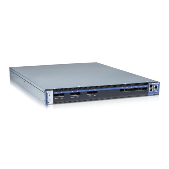
Figure 1: Connector Side View of the Switch Features 1.1.1 Full Feature List • 6 FDR10 (40Gb/s) QSFP Long haul ports (aggregate data throughput up to 240Gb/s) • 6 FDR (56Gb/s) QSFP down link ports (aggregate data throughput up to 336Gb/s) Mellanox Technologies... -
Page 11: Serial Number And Product Version Information
Pull out tab S/N : M T1 11 7 X 00 0 1 4 P/N : M TX 6 1 0 0‐2 SFS R ev:A 2 G U ID : 0 0 02C 9 02 0 0 4 0D D B0 Mellanox Technologies... -
Page 12: Chapter 2 Basic Operation
Status LEDs 2.1.1.1 System Status Indicators The System Status Indicators are located to the left of the connectors on the connector side panel, and on the power side at the far right. Both of these LEDs give identical information. Mellanox Technologies... -
Page 13: Figure 4: System Status Indicators
For more information See “Troubleshooting” on page 51. If the PS LEDs are not green, this indicates a problem with the power supplies. The switch is operational only if at least one of the PS LEDs is green. Mellanox Technologies... -
Page 14: Figure 5: Fan Status Led Connector Side
Figure 5: Fan Status LED Connector Side This is a two color LED Green — OK Red — Major fault Off — No power to the fans The LED indicator on the Fan Module is on the right side of the module. Mellanox Technologies... -
Page 15: Figure 6: Fan Status Led Power Side
If the switch shuts down due to over temperature, unplug the switch, wait 5 minutes and replug in the switch. For more information See “Troubleshooting” on page 51. 2.1.1.3 Power Supply Status Indicators The indicator is located to the left of the connectors on the connector side panel. Mellanox Technologies... -
Page 16: Figure 7: Power Status Led Connector Side
Figure 9: PS Unit Status LEDs This is a two color LED Green — OK Red — Major fault Off — No power to the system Power supply fan air flow indicator Mellanox Technologies... -
Page 17: Figure 10: Bad Port Led
2.1.1.5 UID LED Switch Identifier The UID LED is a debug feature that lights a blue LED on the switch connector side panel for ease in finding a particular switch. Mellanox Technologies... -
Page 18: Air Flow
LED will change to green. When data is being transferred the light will blink green. Air Flow These switches can come with two air flow patterns. The two patterns are: • Connector side inlet to power side outlet • Power side inlet to connector side outlet Mellanox Technologies... -
Page 19: Figure 12: All Components Need The Same Air Flow
All PS units must have the same air flow as the fan module. Figure 12: All Components Need the Same Air Flow These air flow labels must be the same. Red is connector side inlet to power side outlet Blue is power side inlet to connector side outlet Mellanox Technologies... -
Page 20: Qsfp Cable Power Budget Classification
3.5W max power per port and can drive the signal up to 10 km. The 6 ports on the right side (numbered 7 -12) are the downlink FDR ports. Four of the six downlink ports can be split to 4 X 10 Gb/s. Mellanox Technologies... -
Page 21: Management And Firmware Updating Interfaces
A harness is included in the package to connect to a DB9 connection on a host PC. Connecting to a local host PC and following the instructions in the Installation Guide, “Configuring the Switch for the First Time”, must be done before any remote Mellanox Technologies... -
Page 22: Reset Button
On the connector side panel under the system LEDs is a reset button. This reset button requires a tool to be pressed. DO NOT use a sharp pointed object such as needle or push pin for pressing the Reset button. Sharp objects can cause damage, use a flat object to push the reset button. Mellanox Technologies... -
Page 23: Figure 16: Reset Button
A quick push of this button performs this reset. When the button is held down for 15 sec- onds the switch is reset and the password is deleted. You will then be able to enter without a pass- word and make a new password for the user “admin”. Mellanox Technologies... -
Page 24: Chapter 3 Installation
5. During Lightning - Electrical Hazard During periods of lightning activity, do not work on the equipment or connect or dis- connect cables. Mellanox Technologies... - Page 25 Caution – Use of controls or adjustment or performance of procedures other than those specified herein may result in hazardous radiation exposure. CLASS 1 LASER PRODUCT and reference to the most recent laser standards: IEC 60 825-1:1993 + A1:1997 + A2:2001 and EN 60825-1:1994+A1:1996+ A2:2001 Mellanox Technologies...
- Page 26 According to the WEEE Directive 2002/96/EC, all waste electrical and electronic equipment (EEE) should be collected separately and not disposed of with regular household waste. Dispose of this product and all of its parts in a responsible and environmentally friendly way. Mellanox Technologies...
-
Page 27: Installation Kits
• HAR000028 – Harness RS232 2M cable – DB9 to RJ-45switches • 1 X – Quick Start Guide • 1 X – China RoHS statement If anything is damaged or missing, contact your customer representative immediately. For customer support go to: www.mellanox.com =>Support => Customer Support Portal Login Mellanox Technologies... -
Page 28: Mechanical Installation
2. Choose which side of the switch you want even with the rack vertical support. Either the side with the power supply units or the side with the QSFP connectors can be even with one of the vertical rack supports. Mellanox Technologies... -
Page 29: Figure 18: Placement Of Switch In Rack
See Figure 19,“Mounting Options”. • Will the connector side be recessed past other equipment in the rack and will this be prob- lematic? • The installation kit allows for a 2” recess of the switch past the vertical support. Mellanox Technologies... -
Page 30: Figure 19: Mounting Options
7 screws per side are needed for the standard switch. 7 screws per side are needed for the standard switch. There are 16 screws in the kit; you will have left over screws. There are 16 screws in the kit; you will have left over screws. Mellanox Technologies... -
Page 31: Figure 21: Inserting The Caged Nuts
Figure 22: Slide the Rail into the Rail Slide This side of the rail kit goes on the side of the rack you will slide the switch into. This is the same side of the switch that will be next to the vertical support. Mellanox Technologies... -
Page 32: Grounding The Switch
Power Connections and Initial Power On The switch platform ships with two power supply units. Each supply has a separate AC recepta- cle. The input voltage is auto-adjusting for 100 - 240VAC, 50-60Hz power connections. The Mellanox Technologies... -
Page 33: Configuring The Switch The First Time
Connect the host PC to the Console (RJ-45) port of the switch system using the supplied cable. Step 1. The Console ports for systems are shown below as examples. Mellanox Technologies... -
Page 34: Figure 25: Console Port
Login (from a serial terminal program) as admin and use admin as password. This starts the Step 3. Mellanox configuration wizard. Go through the Mellanox configuration wizard. Table 11 shows an example of a wizard session. Step 4. Mellanox Technologies... -
Page 35: Table 11: Configuration Wizard Session - Ip Configuration By Dhcp
Step 3: Enable IPv6? [yes] yes The management interface will be able to use IPv6 addresses. Step 4: Enable IPv6 autoconfig (SLAAC) on mgmt0 This turns on autoconfiguration of the IPv6 addresses. interface? [no] no This is unsuitable for DHCPv6. Mellanox Technologies... - Page 36 Config mode. Otherwise hit <enter> to save changes and exit. Choice: <Enter> Configuration changes saved. To return to the wizard from the CLI, enter the “con- figuration jump-start” command from configuration mode. Launching CLI... <switch name> [> Mellanox Technologies...
-
Page 37: Table 12: Configuration Wizard Session - Ip Zeroconf Configuration
To change an answer, enter the step number to return to. Otherwise hit <enter> to save changes and exit. Choice: Configuration changes saved. To return to the wizard from the CLI, enter the "configuration jump-start" command from configure mode. Launching CLI... switch-1 > Mellanox Technologies... -
Page 38: Table 13: Configuration Wizard Session - Static Ip Configuration
Before attempting a remote (for example, SSH) connection to the switch, check the mgmt0 Step 5. interface configuration. Specifically, verify the existence of an IP address. To check the current mgmt0 configuration, enter the following commands: sx-43 [standalone: master] > enable sx-43 [standalone: master] # show interfaces mgmt0 Mellanox Technologies... -
Page 39: Rerunning The Wizard
TX carrier: RX frame: TX collisions: TX queue len: 1000 Rerunning the Wizard If you want to rerun the wizard run the following commands: sx-43 [standalone: master] > enable sx-43 [standalone: master]# configure terminal sx-43 [standalone: master]# configuration jump-start Mellanox Technologies... -
Page 40: Connecting To The Switch Platform
<switch_IP_address> is the IP address of the switch. rem_mach1 > ssh -l <username> <switch ip address> Mellanox MLNX-OS Switch Management Password: Last login: Thu Apr 28 11:24:13 2011 from 192.168.10.1 Mellanox Switch sx-43 [standalone: master] > You can enter any supported command now. Step 4. Mellanox Technologies... -
Page 41: Chapter 4 Extracting And Inserting Frus
PS units. If the PS unit airflow direction is different from the fan module airflow direction the switch internal temper- ature will be affected. Figure 27: Power Supply Unit Extraction Push Here Latch release Mellanox Technologies... -
Page 42: Extracting And Inserting The Fan Unit
This switch can operate indefinitely with less than a full compliment of fans in the fan module inoperable so long as the ambient temperature is below 45° Celsius. Operation without a fan unit should not exceed two minutes. During fan hot-swap, if the LED indicator is OFF then the fan unit is disconnected. Mellanox Technologies... -
Page 43: Figure 29: Air Flow Labels
The green fan status indicator should light. If not, extract the fan unit and reinsert it. After two unsuccessful attempts to install the fan unit, power off the switch before attempting any system debug. Mellanox Technologies... -
Page 44: Chapter 5 Cabling
Figure 31: Breakout or Fanout Cable Figure 32: Port Splitting Options EXT 1 EXT 2 EXT 3 EXT 4 EXT 5 EXT 6 This port can be split into 4 10Gb/s SFP+ The maximum 10 Gb/s Ethernet ports configurable with this switch is 24. Mellanox Technologies... -
Page 45: Cable Installation
Care should be taken not to impede the air flow through the ventilation holes next to the connec- tor ports. Cable lengths should be used which allow for routing horizontally around to the side of the chassis before bending upward or downward in the rack. Mellanox Technologies... -
Page 46: Chapter 6 Switch Shut Down Procedure
Switch Shut Down Procedure To shut down the switch run the command: Reload halt [noconfirm] The switch cannot be restarted remotely! To restart the switch you must physically go to the switch and unplug and plug in the power cord. Mellanox Technologies... -
Page 47: Chapter 7 Disassembly Of The Switch From The Rack
Dispose of this product and all of its parts in a responsible and environmentally friendly way. Follow the instructions found in the Mellanox Web site at mellanox.com for proper instructions to disassemble and dispose of the Switch according to the WEEE directive. Mellanox Technologies... -
Page 48: Chapter 8 Resetting The Switch
A quick push of this button performs this reset. When the button is held down for 15 sec- onds the switch is reset and the password is deleted. You will then be able to enter without a pass- word and make a new password for the user “admin”. Mellanox Technologies... -
Page 49: Chapter 9 Management And Tools Overview
The chassis management includes the following features: ® • Upgrading SwitchX -2 firmware • Upgrading software • Monitoring of: • AC power to the PSUs • DC power out from the PSUs • Board temperature • Fan module status Mellanox Technologies... -
Page 50: Infiniband Subnet Manager
Use the CLI or the GUI in order to perform Software upgrades. For further information please refer to the MLNX-OS User Manual. Be sure to read and follow all of the instructions regarding the updating of the software on your switch system. Mellanox Technologies... -
Page 51: Chapter 10 Troubleshooting
4. If media adapters are used, check that the all connections are good, tight, and secure. The activity LED does not come on: When running IB check that the Subnet Manager has been started. The switch is off: 1. Unplug the switch. 2. Wait 5 minutes. 3. Plug in the switch. Mellanox Technologies... - Page 52 32 kB I-Cache 32 kB D-Cache Board: Mellanox PPC460EX Board FDEF: I2C: ready DRAM: 2 GB (ECC enabled, 400 MHz, CL3) FLASH: 16 MB NAND: 1024 MiB PCI: Bus Dev VenId DevId Class Int PCIE0: link is not up. Mellanox Technologies...
- Page 53 15b3 bd34 0c06 Net: ppc_4xx_eth0, ppc_4xx_eth1 Hit Ctrl+B to stop autoboot: Mellanox MLNX-OS Boot Menu: 1. EFM_PPC_M460EX EFM_1.1.1000 2010-06-24 16:32:03 ppc 2. EFM_PPC_M460EX EFM_1.1.1200 2010-06-25 18 :00:03 ppc 3. U-Boot prompt Choice: 5. Select the image to boot. Mellanox Technologies...
-
Page 54: Appendix A Specification
-40° to 70° Celsius Shock and Humidity: Shock and Vibration: ETSI EN 300 019-2-2: 1999-09 Operating 5% - 95% non-condensing Vibration/ Humidity Protocol Support Management: Speed protocol \ Auto-Negotiation of (56Gb/s, Managed using MLNX-OS QoS / Management 40Gb/s, 10Gb/s, 1Gb/s) Mellanox Technologies... -
Page 55: Approved Cables
For a list of all approved cables see: http://www.mellanox.com/related-docs/user_manuals/Mellanox_approved_cables.pdf EMC Certifications The list of approved certifications per switch in different regions of the world is located on the Mellanox Website at: http://www.mellanox.com/related-docs/user_manuals/Regulatory_and_Compliance_Guide.pdf EMC statements are also in the Regulatory and Compliance Guide. Mellanox Technologies... -
Page 56: China Ccc Warning Statement
Rev 1.1 China CCC Warning Statement Mellanox Technologies... -
Page 57: Appendix B Qsfp Interface
Receiver Inverted Data Output 3 Rx4p Receiver Non-Inverted Data Out- put 3 Ground ModPrsL Module Present IntL Interrupt Vcc Tx +3.3 V Power supply transmitter Vcc 1 +3.3 V Power Supply LPMode Low Power Mode Ground Tx3p Transmitter Non-Inverted Data Mellanox Technologies... -
Page 58: Figure 34: Qsfp Connector Male And Female Views
Rev 1.1 Figure 34: QSFP Connector Male and Female Views 18.35 View into Rear of Connector 8.50 18.35 View into Front of Cage 8.50 Mellanox Technologies... -
Page 59: Appendix C Rj-45 Console And Ethernet Interfaces
RJ45_RTS# RXD+ RJ45_DTR# TXD+ RJ-45_RTS# 1 RJ45_TXD RXD- TXD- RJ-45_DTR# 2 RJ45_RXD RXD+ RJ-45_TXD Pin 8 Looking into the Socket Bl/W RXD- RJ-45_RXD Br/W TXD+ Pin 1 TXD- RJ45_SDA RXD+ RXD- RJ45_SCL Pin 8 Looking into the Socket Mellanox Technologies... -
Page 60: Appendix D Accessory And Replacement Parts
300W Power Supply w/ Connector side to Power Supply side air flow MSX60-PR Power cord Type C13-C14 ACC000500 Installation Kit for short switches in racks 40-60 cm deep MSX60-BKIT Installation Kit for short or standard switches in racks 60-80 cm deep MSX60-SKIT Mellanox Technologies... -
Page 61: Appendix E Avertissements De Sécurité D'installation (French)
6. Orages – dangers électriques Pendant un orage, il ne faut pas utiliser le matériel et il ne faut pas brancher ou débrancher les câbles. Mellanox Technologies... - Page 62 12. Ajouter une information de connexion à la masse Connect a Valid Ground to this Device Avant de brancher l’appareil à la conduite d’alimentation, les vis de protection à la terre du terminal de l’appareil doivent être appliquées à l’installation de protection à la Terre du bâtiment. Mellanox Technologies...
- Page 63 PRODUIT LASER DE CLASSE 1 » et références aux normes laser les plus récentes CEI 60 825-1:1993 + A1:1997 + A2:2001 et NE 60825-1:1994+A1:1996+ A2:2001 Mellanox Technologies...
- Page 64 Conformément à la Directive WEEE 2002/96/EC, les déchets d'équipements élec- triques et électroniques (EEE) doivent être triés et ne peuvent être éliminés avec les déchets ménagers. Veuillez disposer de ce produit et de tous ses composants de manière responsable et respectueuse de l’environnement. Mellanox Technologies...
-
Page 65: Appendix F Installation - Sicherheitshinweise (German)
Anschlüsse angebracht bzw. davon getrennt werden. Lesen Sie die speziellen Warnun- gen und Anleitungen des Kabelherstellers. 7. Gafahr des elektrischen Schocks. Gafahr des elektrischen Schocks. Entferrnen des Netzsteckers elnes Netzteils span- nungsfrei. Um alle Einhieten spannungsfrei zu machen sind die Netzstecker aller Netz- teile zu entfernen Mellanox Technologies... - Page 66 Achtung – Nutzung von Steuerungen oder Einstellungen oder Ausführung von Proze- duren, die hier nicht spezifiziert sind, kann zu gefährlichem Strahlenkontakt führen.. Klasse 1 Laserprodukt und Referenzen zu den aktuellsten Lasterstandards : ICE 60 825-1:1993 + A1:1997 + A2:2001 und EN 60825-1:1994+A1:1996+ A2:2001 Mellanox Technologies...
- Page 67 19. Zweipolige bzw. Neutralleiter-Sicherung im Netzteil Achtung: Zweipolige bzw. Neutralleiter-Sicherung im Netzteil. Netzstecker ziehen, um sicher- zustellen, daß keine Spannung am Gerät anliegt. Entfernen Sie alle Netzkabel vor dem Öffnen der Abdeckung dieses Produkts oder dem Berühren der Innenteile. Mellanox Technologies...
- Page 68 20. Bodily Injury Due to Weight Use enough people to safely lift this product. <40 lbs 70 - 121 lbs >121 lbs 40 - 70 lbs <18 kgs 32 - 55 kgs >55 kgs 18 - 32 kgs Mellanox Technologies...
-
Page 69: Appendix G Advertencias De Seguridad Para La Instalación (Spanish)
6. Dos fusibles, uno en el polo y otro en el neutro Dos fusibles, uno en el polo y otro en el neutro. Quitar los cables de corriente antes de abrir la tapa de este producto o tocar cualquier componente interno. Mellanox Technologies... - Page 70 12. Eliminación de equipos La eliminación definitiva de este equipo se debe efectuar conforme a todas las leyes y reglamentaciones nacionales. 13. Códigos eléctricos locales y nacionales Este equipo se debe instalar conforme a los códigos eléctricos locales y nacio- nales. Mellanox Technologies...
- Page 71 (EEE) se deben recolectar por separado y no se deben eliminar junto con residuos domésticos. Al deshacerse de este producto y de todas sus partes, hágalo de una manera respon- sable y respetuosa con el medio ambiente. Mellanox Technologies...
Need help?
Do you have a question about the TX6100 MetroX Series and is the answer not in the manual?
Questions and answers