Sign In
Upload
Manuals
Brands
Mellanox Technologies Manuals
Switch
TX6100 MetroX Series
Mellanox Technologies TX6100 MetroX Series Manuals
Manuals and User Guides for Mellanox Technologies TX6100 MetroX Series. We have
2
Mellanox Technologies TX6100 MetroX Series manuals available for free PDF download: Hardware User Manual
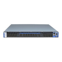
Mellanox Technologies TX6100 MetroX Series Hardware User Manual (89 pages)
Long Haul Systems
Brand:
Mellanox Technologies
| Category:
Switch
| Size: 3 MB
Table of Contents
Table of Contents
3
Revision History
7
Table 1: Revision History Table
7
About this Manual
8
Table 2: References
8
Chapter 1 Introduction to Mellanox TX6000/TX6100 Long Haul Systems
9
Overview
9
Figure 1: Long Haul TX6000/TX6100 Front Side View
9
Speed and Switching
10
Management Interfaces and Frus
10
Features
10
Network Management Features
10
Infiniband Features
10
Table 3: Speed and Switching Capabilities
10
Table 4: Management Interfaces and Frus
10
Long Haul Features
11
Certifications
11
Ordering Information
11
Table 5: Ordering Part Numbers (Opns)
11
Chapter 2 Installation
12
Safety Warnings
12
Air Flow
13
Table 6: Air Flow Label Legend
13
Figure 2: Air Flow Direction Marking - Connector Side Inlet to Power Side Outlet
14
Figure 3: Air Flow Direction Marketing - Power Side Inlet to Connector Side Outlet
14
Package Contents
15
Mounting Options
16
19" Systems Mounting
16
Figure 4: Rack Rail Kit Parts
16
Table 7: Installation Kit Options
16
Figure 5: Screwing on the Rail
17
Figure 6: Inserting the Caged Nuts
18
Figure 7: Slide the Rail into the Rail Slide
18
Figure 8: Installing the Slides
19
Figure 9: System Placement in the Rack
20
Figure 10: Installation Completed
20
Grounding
21
Cable Installation
22
Using a Breakout Cable
22
Figure 11: Cable Orientation
22
Initial Power on
23
Figure 12: Breakout or Fanout Cable
23
Figure 13: System Status Leds 5 Minutes after Power on
24
System Bring-Up
25
Configuring Network Attributes
25
Figure 14: Two Power Inlets - Electric Caution Notifications
25
Table 8: Serial Terminal Program Configuration
25
Table 9: Configuration Wizard Session - DHCP
26
Table 10: Configuration Wizard Session - Static IP Configuration
27
Remote Connection
28
FRU Replacements
29
Power Supply and Fans
29
Figure 15: Power Supply Unit Extraction
30
Figure 16: PS Unit Pulled out
30
Figure 17: Fan Module Latches
31
Chapter 3 Interfaces
33
Supported Interfaces
33
Data Interfaces
33
Speed
33
RS232 (Console)
33
Management
33
Usb
34
I2C
34
Reset Button
34
Leds
35
LED Notifications
35
Table 11: Status Leds
35
Status Leds
36
Figure 18: System Status Leds - Front and Rear Sides
36
Table 12: System Status LED Assignments
36
Figure 19: Fan Status LED - Front and Rear Sides
37
Table 13: Fan Status LED Assignments
37
Figure 20: Power Status LED
38
Figure 21: Rear Side Panel
38
Table 14: Power Supply Unit Status LED Assignments
38
Port Leds
39
Figure 22: Port Leds
39
Table 15: Bad Port LED Assignments
39
Table 16: Port Leds in Infiniband System Mode
39
Inventory Pull-Out Tab
41
Figure 23: Pull-Out Tab
41
Chapter 4 Software Management
42
Upgrading Software
42
Chapter 5 Troubleshooting
43
Troubleshooting Instructions
43
Table 17: Troubleshooting
43
Chapter 6 Specifications
45
TX6000 System
45
Table 18: TX6000 Specifications
45
TX6100 System
46
Table 19: TX6100 Specifications
46
Appendix A Accessory and Replacement Parts
47
Table 20: Opns for Replacement Parts
47
Appendix B Thermal Threshold Definitions
48
Appendix C Interface Specifications
49
QSFP Interface
49
Figure 24: QSFP Connector Male and Female Views
50
Table 21: RJ-45 CONSOLE Pinout
51
Table 22: RJ-45 I2C Pinout
51
Appendix D Disassembly and Disposal
52
Disassembly Procedure
52
Appendix E Safety Warnings (Multiple Languages)
53
Nordic Countries Notices
53
Installation Safety Warnings (English)
53
安裝安全性警告 (Chinese)
56
Avertissements de Sécurité pour L'installation (French)
61
Installation Sicherheitshinweise(German)
64
Advertencias de Seguridad de Instalación (Spanish)
67
Предупреждения По Технике Безопасности При Установке
71
(Russian)
71
Avertismente Privind Siguranţa la Instalare (Romanian)
74
Sigurnosna Upozorenja Za Instaliranje (Croatian)
78
Avvertenze DI Sicurezza Per L'installazione (Italiano)
81
Montaj Güvenlik Uyarıları (Türkçe)
86
Advertisement
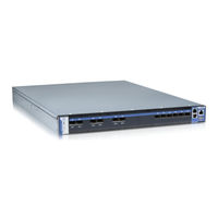
Mellanox Technologies TX6100 MetroX Series Hardware User Manual (71 pages)
InfiniBand Long Haul System
Brand:
Mellanox Technologies
| Category:
Switch
| Size: 1 MB
Table of Contents
Table of Contents
3
List of Figures
5
List of Tables
6
Revision History
7
Table 1: Revision History Table
7
About this Manual
8
Conventions
8
Intended Audience
8
Related Documentation
8
Table 2: Reference Documents and Web Sites
8
Abbreviations
9
Mellanox Part Numbering Legend
9
Chapter 1 Overview
10
Features
10
Full Feature List
10
Figure 1: Connector Side View of the Switch
10
Serial Number and Product Version Information
11
Figure 2: Pull out Tab
11
Chapter 2 Basic Operation
12
Switch Platform Hardware Overview
12
Status Leds
12
Figure 3: QSFP Switch System Power and Connector Side Panels
12
Figure 4: System Status Indicators
13
Figure 5: Fan Status LED Connector Side
14
Table 3: System Status LED Assignments
14
Figure 6: Fan Status LED Power Side
15
Table 4: Fan Status LED Assignments
15
Figure 7: Power Status LED Connector Side
16
Figure 8: Power Side Panel
16
Figure 9: PS Unit Status Leds
16
Figure 10: Bad Port LED
17
Table 5: PS Unit Status LED Assignments
17
Table 6: Bad Port LED Assignments
17
Air Flow
18
Figure 11: Port Leds
18
Table 7: Connector Physical and Logical Link Assignments for IB
18
Figure 12: All Components Need the same Air Flow
19
QSFP Cable Power Budget Classification
20
Interfaces
20
Port Connector Interfaces
20
Table 8: Air Flow Direction
20
Management and Firmware Updating Interfaces
21
Figure 13: Port Numbering
21
Figure 14: Top and Bottom QSFP Port Orientation
21
Figure 15: Management Interfaces
21
Reset Button
22
Figure 16: Reset Button
23
Chapter 3 Installation
24
Installation Safety Warnings
24
Installation Kits
27
Package Contents
27
Table 9: Installation Kit According to Rack Size
27
Mechanical Installation
28
Figure 17: Rack Rail Kit Parts
28
Figure 18: Placement of Switch in Rack
29
Figure 19: Mounting Options
30
Figure 20: Screwing on the Rail
30
Figure 21: Inserting the Caged Nuts
31
Figure 22: Slide the Rail into the Rail Slide
31
Grounding the Switch
32
Power Connections and Initial Power on
32
Figure 23: Status Leds 5 Minutes after Power on
32
Configuring the Switch the First Time
33
Figure 24: Two Power Inlets - Electric Caution Notifications
33
Figure 25: Console Port
34
Table 10: Serial Terminal Program Configuration
34
Table 11: Configuration Wizard Session - IP Configuration by DHCP
35
Table 12: Configuration Wizard Session - IP Zeroconf Configuration
37
Table 13: Configuration Wizard Session - Static IP Configuration
38
Rerunning the Wizard
39
Connecting to the Switch Platform
40
Starting a Remote Connection to the Switch
40
Starting an SSH Connection to the Switch (CLI)
40
Chapter 4 Extracting and Inserting Frus
41
Extracting and Inserting the Power Supply Unit
41
Figure 26: Fan and PS Unit Air Flow Direction
41
Figure 27: Power Supply Unit Extraction
41
Extracting and Inserting the Fan Unit
42
Figure 28: PS Unit Pulled out
42
Figure 29: Air Flow Labels
43
Figure 30: Fan Module Latches
43
Chapter 5 Cabling
44
Supported Approved Cables
44
Splitting the Data Stream Using Breakout (Fanout) Cables
44
Figure 31: Breakout or Fanout Cable
44
Figure 32: Port Splitting Options
44
Cable Installation
45
Chapter 6 Switch Shut down Procedure
46
Chapter 7 Disassembly of the Switch from the Rack
47
Disposal
47
Chapter 8 Resetting the Switch
48
Figure 33: Reset Button
48
Chapter 9 Management and Tools Overview
49
Switch Management Using the MLNX-OS™ Software
49
Switch Management
49
Infiniband Subnet Manager
50
Fabric Inspector (Diagnostics)
50
Upgrading Software
50
Chapter 10 Troubleshooting
51
Appendix A Specification
54
Table 14: TX6100 Specification Data
54
Approved Cables
55
EMC Certifications
55
China CCC Warning Statement
56
Appendix B QSFP Interface
57
Table 15: Infiniband QSFP Connector Pinout
57
Figure 34: QSFP Connector Male and Female Views
58
Appendix C RJ-45 CONSOLE and Ethernet Interfaces
59
Table 16: RJ-45 Pinout
59
Appendix D Accessory and Replacement Parts
60
Table 17: Replacement Parts Ordering Numbers
60
Appendix E Avertissements de Sécurité D'installation (French)
61
Appendix F Installation - Sicherheitshinweise (German)
65
Appendix G Advertencias de Seguridad para la Instalación (Spanish)
69
Advertisement
Related Products
Mellanox Technologies TX6000
Mellanox Technologies MetroX TX6240
Mellanox Technologies MetroX TX6280
Mellanox Technologies 1G Switch Air Duct Rail Kit
Mellanox Technologies Grid Director 2036
Mellanox Technologies Grid Director 4036
Mellanox Technologies Grid Director 4036E
Mellanox Technologies Grid Director 4200
Mellanox Technologies Grid Director 4700
Mellanox Technologies InfiniScale III
Mellanox Technologies Categories
Switch
Computer Hardware
Adapter
Network Card
Network Router
More Mellanox Technologies Manuals
Login
Sign In
OR
Sign in with Facebook
Sign in with Google
Upload manual
Upload from disk
Upload from URL