Table of Contents
Advertisement
Quick Links
Advertisement
Table of Contents

Related Manuals for Saluki S1132 Series


Summary of Contents for Saluki S1132 Series
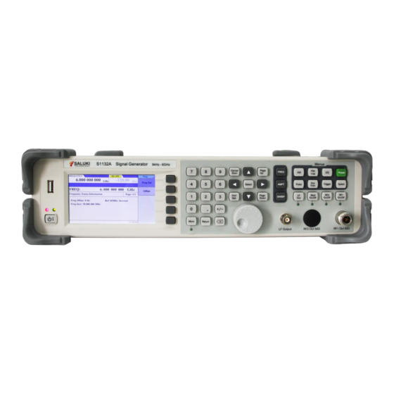
- Page 1 S1132 Series Multi-Standard Signal Generator User Manual Saluki Technology Inc.
- Page 2 1x Power Cord Assembly 1x Product Certificate 1x Coaxial Adapter Options of S1132 series signal generator in addition to standard accessories : Option No. Description S1132-02 RF Upper Conversion Device S1132-03 Analog External Audio Modulation S1132-05...
- Page 3 Saluki. Saluki Tech owns the copyright of this document which should not be modified or tampered by any organization or individual or reproduced or transmitted for the purpose of making profit without its prior permission, otherwise Saluki will reserve the right to investigate and affix legal liability of infringement.
-
Page 4: Table Of Contents
Tel: 886. 909 602 109 Email: sales@salukitec.com www.salukitec.com Content 1 Overview..................................5 1.1 Product Overview..............................5 1.2 Electrical Safety..............................5 1.3 Operation Precautions............................6 2 Interfaces & Buttons..............................8 2.1 Front Panel................................8 2.2 Rear Panel................................8 3 Operation Guide................................10 3.1 Continuous Wave Signal............................ 10 3.2 Sweep Signal...............................11 3.3 Analog Modulation Signal..........................15 3.4 Digital Modulation Signal.......................... -
Page 5: Overview
Each type of product has outstanding features in its function to characterize the focus of its testing field. S1132 series signal generator features a variety of key analog modulation functions (AM/FM/ФM/pulse modulation), standard digital modulation functions (ASK/PSK/FSK) and customizable dedicated modulation methods (SSB/DSB/CW modulation, etc.). -
Page 6: Operation Precautions
Tel: 886. 909 602 109 Email: sales@salukitec.com www.salukitec.com According to the power requirements of the real panel of the instrument, a three-core power cord should be adopted while ensuring reliable grounding of the ground wire during operation. Either floating ground or poor grounding may cause damage to the instrument and even cause injury to operators. - Page 7 Tel: 886. 909 602 109 Email: sales@salukitec.com www.salukitec.com or poor grounding may damage the signal generator and even cause personal injury. In order to prevent or reduce the mutual interference caused by multiple devices through the power supply, especially the spike interference generated by high-power devices may cause damage to the instrument hardware, it is best to use a 220V/110V AC stabilized power supply to power the adapter.
-
Page 8: Interfaces & Buttons
Tel: 886. 909 602 109 Email: sales@salukitec.com www.salukitec.com 2 Interfaces & Buttons This chapter introduces the front panel, rear panel and button of the S1132 signal generator. 2.1 Front Panel Figure 2-1 Front panel of S1132 signal generator Description Description USB interface Function button zone Soft menu... - Page 9 Tel: 886. 909 602 109 Email: sales@salukitec.com www.salukitec.com Description Description Power input TRIG IN 10MHz IN/OUT TRIG OUT AF IN Fan port SWEEP OUT USB interface Ext IF Input LAN interface PULSE IN RS232 interface PULSE OUT...
-
Page 10: Operation Guide
Tel: 886. 909 602 109 Email: sales@salukitec.com www.salukitec.com 3 Operation Guide This chapter introduces the function and usage of the S1132 signal generator through examples. The contents of this chapter are as follows: Continuous Wave Signal Sweep Signal Analog Modulation Signal ... -
Page 11: Sweep Signal
Tel: 886. 909 602 109 Email: sales@salukitec.com www.salukitec.com — Press【RF1】 button, make the【RF1】button backlight bright 3. Test result After setting the relevant parameters of the spectrum analyzer, a continuous wave signal can be observed on the screen, with a frequency of 1 GHz and an amplitude of -10.46 dBm, as shown in Figure 3-1. Figure 3-1 Test result of the CW signal 3.2 Sweep Signal The S1132 signal generator can output signals in three modes: frequency sweep, amplitude sweep, and frequency +... - Page 12 Tel: 886. 909 602 109 Email: sales@salukitec.com www.salukitec.com 1. Instrument connection Use a coaxial cable to connect the signal output end of the signal generator to the RF input port of the N9020A spectrum analyzer. 2. Parameter setting (1) Reset the signal generator —...
- Page 13 Tel: 886. 909 602 109 Email: sales@salukitec.com www.salukitec.com Figure 3-2 Test result of the frequency sweep signal 3.2.2 Frequency + Amplitude sweep signal Frequency sweep signal refers to the frequency and amplitude sweep from the start value to the end value at the same time.
- Page 14 Tel: 886. 909 602 109 Email: sales@salukitec.com www.salukitec.com — Press【AMPT】 button, input -10 dBm — Press【Sweep】 button — Select [SWP Mode] — Select [Freq & Ampl] — Select [CFG Step] — Select [Freq Start], input 1 GHz — Select [Freq Stop], input 2 GHz —...
-
Page 15: Analog Modulation Signal
Tel: 886. 909 602 109 Email: sales@salukitec.com www.salukitec.com Figure 3-3 Test result of the frequency + amplitude sweep signal 3.3 Analog Modulation Signal The S1132 signal generator can output AM/FM/PM analog modulation signals. The following introduces various modulation signals with carrier frequency of 1GHz and amplitude of -10dBm. 3.3.1 AM For example: modulation depth 50%, modulation rate 50kHz Operation steps:... - Page 16 Tel: 886. 909 602 109 Email: sales@salukitec.com www.salukitec.com — Press【FREQ】 button, input 1 GHz — Press【AMPT】 button, input -10 dBm — Press【RF1】 button, make the【RF1】button backlight bright — Select [Depth], input 50% — Select [Int Fctn] -- “Frequency”, input 50 kHz —...
- Page 17 Tel: 886. 909 602 109 Email: sales@salukitec.com www.salukitec.com 3.3.2 FM For example: frequency offset 500kHz, modulation rate 50kHz Operation steps: 1. Instrument connection Use a coaxial cable to connect the signal output end of the signal generator to the RF input port of the N9020A spectrum analyzer.
- Page 18 Tel: 886. 909 602 109 Email: sales@salukitec.com www.salukitec.com Figure 3-5 Test result of the FM modulation signal 3.3.3 ФM For example: phase offset 180°, modulation rate 100kHz Operation steps: 1. Instrument connection Use a coaxial cable to connect the signal output end of the signal generator to the RF input port of the N9020A spectrum analyzer.
- Page 19 Tel: 886. 909 602 109 Email: sales@salukitec.com www.salukitec.com — Press【RF1】 button, make the【RF1】button backlight bright — Press【FM/ФM】 button — Select [Mode] -- “ M” — Select [Phase Offset], input 180° — Select [Int Fctn] — Select [Freq], input 100 kHz —...
-
Page 20: Digital Modulation Signal
Tel: 886. 909 602 109 Email: sales@salukitec.com www.salukitec.com 3.4 Digital Modulation Signal The S1132 signal generator can output ASK/FSK/PSK digital modulation signals. The following introduces various modulation signals with carrier frequency of 1GHz and amplitude of -10dBm. 3.4.1 ASK Modulation For example: 2ASK mode, modulation depth 50%, rate 100kHz Operation steps: 1. - Page 21 Tel: 886. 909 602 109 Email: sales@salukitec.com www.salukitec.com — Press【Return】 button — Press【MOD】 button, make the【MOD】button backlight bright 3. Test result After setting the relevant parameters of the spectrum analyzer, the result is shown in Figure 3-7. Figure 3-7 Test result of the ASK modulation signal 3.4.2 FSK Modulation For example: 2FSK mode, rate 100kHz Operation steps:...
- Page 22 Tel: 886. 909 602 109 Email: sales@salukitec.com www.salukitec.com — Press【Preset】 button (2) Parameter setting — Press【FREQ】 button, input 1 GHz — Press【AMPT】 button, input -10 dBm — Press【RF1】 button, make the【RF1】button backlight bright — Press【AuxFctn】 button — Select [Digital Mod] —...
- Page 23 Tel: 886. 909 602 109 Email: sales@salukitec.com www.salukitec.com Figure 3-8 Test result of the FSK modulation signal 3.4.3 PSK Modulation For example: 2PSK mode, rate 100kHz Operation steps: 1. Instrument connection Use a coaxial cable to connect the signal output end of the signal generator to the RF input port of the N9020A spectrum analyzer.
- Page 24 Tel: 886. 909 602 109 Email: sales@salukitec.com www.salukitec.com — Press【RF1】 button, make the【RF1】button backlight bright — Press【AuxFctn】 button — Select [Digital Mod] — Select [State] -- “On” — Select [Mode] — Select [PSK] — Select [2PSK] — Press【Return】 button — Select [Parameter] —...
-
Page 25: Pulse Modulation Signal
Tel: 886. 909 602 109 Email: sales@salukitec.com www.salukitec.com Figure 3-9 Test result of the PSK modulation signal 3.5 Pulse Modulation Signal The S1132 signal generator can output pulse modulation signals. The following example introduces the pulse modulation signal with carrier frequency of 1GHz and amplitude of -10dBm. Operation steps: 1. - Page 26 Tel: 886. 909 602 109 Email: sales@salukitec.com www.salukitec.com — Press【AMPT】 button, input -10 dBm — Press【RF1】 button, make the【RF1】button backlight bright — Press【Pulse】 button — Select [Trig Mod] — Select [Free Run] — Select [Source] -- “INT” — Select [Period], input 200 ms —...
-
Page 27: Lf Output
Tel: 886. 909 602 109 Email: sales@salukitec.com www.salukitec.com Figure 3-10 Test result of the pulse modulation signal 3.6 LF Output The S1132 signal generator can output low frequency signals including Sine, Square, Triangle and Sawtooth. 3.6.1 Sine wave For example: to output LF signal with frequency of 100kHz and amplitude of 1Vpp. Operation steps: 1. - Page 28 Tel: 886. 909 602 109 Email: sales@salukitec.com www.salukitec.com — Press【AuxFctn】 button — Select [LF OUT] — Select [Wave] — Select [Sine] — Select [Freq], input 100 kHz — Select [AMPL], input 1 Vpp — Press【LF】 button, make the【LF】button backlight bright 3.
- Page 29 Tel: 886. 909 602 109 Email: sales@salukitec.com www.salukitec.com 2. Parameter setting (1) Reset the signal generator — Press【Preset】 button (2) Parameter setting — Press【AuxFctn】 button — Select [LF OUT] — Select [Wave] — Select [Square] — Select [Freq], input 20 kHz —...
- Page 30 Tel: 886. 909 602 109 Email: sales@salukitec.com www.salukitec.com 3.6.3 Triangle wave For example: to output LF signal with frequency of 100kHz and amplitude of 1Vpp. Operation steps: 1. Instrument connection Use a coaxial cable to connect the LF output port of the signal generator to the channel 1 input end of the MSO-X2020A oscilloscope.
- Page 31 Tel: 886. 909 602 109 Email: sales@salukitec.com www.salukitec.com Figure 3-13 Test result of the triangle wave signal 3.6.4 Sawtooth wave For example: to output LF signal with frequency of 100kHz and amplitude of 1Vpp. Operation steps: 1. Instrument connection Use a coaxial cable to connect the LF output port of the signal generator to the channel 1 input end of the MSO-X2020A oscilloscope.
-
Page 32: Up-Conversion Function
Tel: 886. 909 602 109 Email: sales@salukitec.com www.salukitec.com — Select [Freq], input 100 kHz — Select [AMPL], input 1 Vpp — Press【LF】 button, make the【LF】button backlight bright 3. Test result After setting the relevant parameters of the oscilloscope, the result is shown in Figure 3-14. Figure 3-14 Test result of the triangle wave signal 3.7 Up-conversion Function The S1132 signal generator has an up-conversion function, which is used to up-convert a signal from 25MHz to... - Page 33 Tel: 886. 909 602 109 Email: sales@salukitec.com www.salukitec.com — Press【Preset】 button (2) Parameter setting Signal generator 1: — Press【FREQ】 button, input 200 MHz — Press【AMPT】 button, input -9.82 dBm — Press【RF1】 button, make the【RF1】button backlight bright Signal generator 2: — Press【FREQ】 button, input 2.7 MHz —...
-
Page 34: Drg
Tel: 886. 909 602 109 Email: sales@salukitec.com www.salukitec.com Figure 3-16 Test result of the up-conversion function 3.8 DRG The S1132 signal generator has linear frequency modulation function. Operation steps: 1. Instrument connection Use a coaxial cable to connect the signal output end of the signal generator to the RF input port of the N9020A spectrum analyzer. - Page 35 Tel: 886. 909 602 109 Email: sales@salukitec.com www.salukitec.com — Select [DRG] — Select [State] -- “On” — Select [Upper Limit], input 1 GHz — Select [Points], input 100 — Select [Rate], input 0.1 μs — Press【More】 button — Select [Mode] —...
-
Page 36: Power Measurement
Tel: 886. 909 602 109 Email: sales@salukitec.com www.salukitec.com 3.8 Power Measurement The S1132 signal generator can perform power measurement by using SUP60 USB power sensor. Operation steps: 1. Instrument connection Use the USB cable to connect the power sensor to the USB port of the signal generator, then connect the signal input port of the power sensor to the RF signal output port of the signal generator. -
Page 37: Remote Control
Tel: 886. 909 602 109 Email: sales@salukitec.com www.salukitec.com 4 Remote Control Users can program and control S1132 signal generator through standard SCPI commands. Users can communicate with PC through instrument buses such as USB and LAN. This chapter introduces in detail how to remotely control the signal generator through various interfaces. -
Page 38: Via Lan Port
Tel: 886. 909 602 109 Email: sales@salukitec.com www.salukitec.com 4.2 Via LAN Port 1. Instrument connection Connect the signal generator to your local area network through the LAN interface. 2. Communication test Open the TCP control software, connect via IP (192.168.1.6) and port number (4060), send commands and read data. -
Page 39: Faults And Repair
Tel: 886. 909 602 109 Email: sales@salukitec.com www.salukitec.com 5 Faults and Repair This chapter lists the common faults and troubleshooting methods that may occur during the use of the signal generator. 5.1 Common Faults and Troubleshooting Methods 1. After powering on, the instrument has a black screen without any display. Check if the fan is spinning: (1) If the fan rotates normally, the connection line of the display screen may be loose. - Page 40 Tel: 886. 909 602 109 Email: sales@salukitec.com www.salukitec.com Service Tel: +886. 909 602 109 Website: www.salukitec.com Email: sales@salukitec.com Address: No. 367 Fuxing N Road, Taipei 105, Taiwan In case of any failure to the signal generator that is difficult to be eliminated, contact us by phone or fax. If it is confirmed by both parties that the signal generator has to be returned for repairing, pack the instrument with the original packing materials and case by following the steps below: 1) Prepare a detailed description of the failure of the signal generator and put it into the package along with the...
-
Page 41: Technical Specifications
Tel: 886. 909 602 109 Email: sales@salukitec.com www.salukitec.com 6 Technical Specifications Model S1132A S1132B Frequency Frequency Range 9kHz - 6GHz Frequency Resolution 0.23Hz Internal Reference Reference Frequency 10MHz Temperature Stability ±0.5ppm (option: ±5ppb) Internal Reference Output 10MHz, +2dBm (typ.) Spectral Purity Harmonic ≤... - Page 42 Tel: 886. 909 602 109 Email: sales@salukitec.com www.salukitec.com Modulation Rate 20Hz - 1MHz 1Hz - 1MHz Modulation Phase 0° - 360° 0° - 360° ФM Modulation Rate 20Hz - 1MHz 1Hz - 1MHz Digital modulation: support internal/external modulation source IQ modulator Nonsupport Support ASK/2FSK/4FSK/8FSK/2...
Need help?
Do you have a question about the S1132 Series and is the answer not in the manual?
Questions and answers