Table of Contents
Advertisement
Quick Links
Advertisement
Table of Contents

Related Manuals for Saluki S1465 Series


Summary of Contents for Saluki S1465 Series
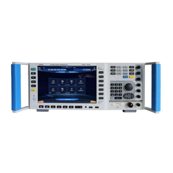
- Page 1 S1465 Series Signal Generator User Manual Saluki Technology Inc.
- Page 2 Name Main machine User manual Power cable assembly Certificate of quality Options of the S1465(-V) series signal generator in addition to standard accessories: (1) S1465 series options: Option ID Description Function Match 115dB programmable step To expand output power dynamic...
- Page 3 Tel: 886.909 602 109 Email: sales@salukitec.com www.salukitec.com Additional pulse modulation, with the All models, including S1465-H02C Narrow pulse modulation minimum pulse width of 20ns H02B S1465-H03 Analog sweep Additional analog sweep (slope sweep) All models To reduce phase noise, S1465-H04 Ultra low phase noise All models 10GHz@10kHz: -120dBc/Hz...
- Page 4 Tel: 886.909 602 109 Email: sales@salukitec.com www.salukitec.com (2) S1465-V series options: Option ID Description Function Match 115dB programmable step To expand output power dynamic For model S1465V-H01A attenuator range S1465C/D/F-V To expand output power dynamic For model S1465V-H01B 90dB programmable step attenuator range S1465H/L-V Additional analog modulation, including...
- Page 5 Tel: 886.909 602 109 Email: sales@salukitec.com www.salukitec.com For power measurement and S1465V-H82 S87232 USB power probe All models calibration (50MHz-26.5GHz) For power measurement and S1465V-H83 S87233 USB power probe All models calibration (50MHz-40GHz) As specified in GJB-151A (touch S1465V-H90 Electromagnetic compatibility All models screen disabled) S1465V-H91...
- Page 6 Tel: 886.909 602 109 Email: sales@salukitec.com www.salukitec.com multiple pulses, repetition frequency jitter, repetition jitter, and repetition frequency slip. (Need option H02B/C)
- Page 7 Manual rests with Saluki. Saluki Tech owns the copyright of this User Manual which should not be modified or tampered by any organization or individual, or reproduced or transmitted for the purpose of making profit without its prior permission, otherwise Saluki will reserve the right to investigate and affix legal liability of infringement.
-
Page 8: Table Of Contents
Tel: 886.909 602 109 Email: sales@salukitec.com www.salukitec.com Content 1 Overview.................................. 9 1.1 General................................9 1.2 Safety guide..............................16 2 Start Guide................................21 2.1 Preparation before use..........................21 2.2 Description of front and rear panels......................36 2.3 Basic configuration method......................... 40 2.4 Data management............................62 3 Operation Guides.............................. -
Page 9: Overview
1.1 General The S1465 series signal generator has a frequency range of 100kHz - 67GHz, excellent spectrum purity and output power, with SSB phase noise of 10GHz carrier @ 10kHz frequency offset of - 126dBc/Hz, max. - Page 10 1.1.1.2 High performance Excellent spectrum purity The S1465 series signal generator can generate high-purity signal spectrum, of SSB phase noise 10GHz carrier@10kHz frequency offset (typical value) -126dBc/Hz, 1GHz carrier@10kHz frequency offset (typical value) -142dBc/Hz, making it applicable for testing of Doppler radar, high-performance receiver blocking and adjacent channel selectivity, and an ideal alternative of local oscillator and low-jitter clock.
- Page 11 Tel: 886.909 602 109 Email: sales@salukitec.com www.salukitec.com S1465F Max. Output Power (Option H05) Frequency /GHz Fig. 1.3 Max. Output Power of S1465F+H05 S1465F-V Max . Output Power(Option H05) frequency/GHz Fig. 1.4 Max. Output Power of S1465F-V+H05 High-vector modulation bandwidth The S1465-V series can generate vector signals of modulation bandwidth 200MHz and 2GHz external (>...
- Page 12 Tel: 886.909 602 109 Email: sales@salukitec.com www.salukitec.com Fig. 1.6 60GHz Carrier 200MHz Modulation Bandwidth Multi-tone Signal 4) Download of high-compatibility arbitrary waveform data format The S1465-V series supports downloading and playing of arbitrary waveform data in storage formats of Mat-File 5, ASCII, Binary, cap, csv and up to the depth of 2G sampling point. Fig.
- Page 13 Large-screen TFT LED gives graphical display and supports operation by screen touch and front-panel keys. The S1465 series signal generator is applied with self-designed software, a large screen and a Chinese/English operation interface to provide a panoramic view of current status information. The interface is of a window-type operation structure, allowing easy operation by keys and screen touch for efficient, flexible and convenient use.
- Page 14 Through the combination of both, users can generate trigger signals according to actual needs of the test. Fig. 1.12 Baseband Gating (Low Effective) Abundant remote interfaces There are multiple remote interfaces available for the S1465 series signal generator, including source module port, GPIB port, network port, for easy remote control and network upgrading.
- Page 15 High-performance receiver test With ultra-low SSB phase noise and excellent anharmonic suppression, the S1465 series signal generator can produce ideal pure signals for testing the phase noise, blocking, adjacent channel selectivity of high-performance receivers used in radars, electronic wars and communication equipment.
-
Page 16: Safety Guide
Excitation signal and local oscillator substitution The S1465 series signal generator has extremely pure signal quality and high output power, making it suitable for signal excitation of various amplifiers and an ideal substitution as a local oscillator for the one in devices under test such as the transmitter, receiver, etc. - Page 17 Tel: 886.909 602 109 Email: sales@salukitec.com www.salukitec.com Table 1.1 Safety Signs on the Product Symbol Meaning Symbol Meaning CAUTION, which indicates information that requires special Power ON/OFF attention from the user, or operation information or instructions require attention from the user. ATTENTION, which represents...
- Page 18 Tel: 886.909 602 109 Email: sales@salukitec.com www.salukitec.com DANGER indicates a situation which, if not being avoided, will lead to ! DANGER personal injury or equipment damage. WARNING indicates a situation which, if not being avoided, will lead to WARNING personal injury or equipment damage. CAUTION indicates a situation which, if not being avoided, will lead to CAUTION minor or moderate personal injury or equipment damage.
- Page 19 Tel: 886.909 602 109 Email: sales@salukitec.com www.salukitec.com The outlet should be kept clean and tidy, and the plug and outlet should be contacted properly and firmly. The outlet and power cord should not be overloaded; otherwise, fire or electric shock will be caused.
- Page 20 Tel: 886.909 602 109 Email: sales@salukitec.com www.salukitec.com 1.2.6 Transportation If the instrument is heavy, please move it carefully, and if necessary, use an aid (such as crane) to move the instrument so as to avoid body damage. The instrument handle is suitable for personal handling, and it should not be used to fix the instrument on the carrier for transportation.
-
Page 21: Start Guide
This chapter contains precautions before use, overview of front and rear panels, common basic configuration methods and data file management of S1465 series signal generator, so that the user can have a preliminary knowledge about the instrument and configuration process. The content contained in this chapter is consistent with that in relevant chapters of Quick Start Guide. - Page 22 CAUTION Handling: As the instrument and its packing carton are heavy, they should be moved by two persons at the same time and be handled with care. Model confirmation Table 2.1 Packing List of S1465 Series Name Quantity Function Main unit: ...
- Page 23 Tel: 886.909 602 109 Email: sales@salukitec.com www.salukitec.com 2.1.1.2 Environmental requirements The operating place of the S1465 series signal generator should meet the following environmental requirements: Operating environment The operating environment should satisfy the following requirements: Table 2.2 Requirements for Operating Environment of Series S1465 Temperature 0°C - 50°C...
- Page 24 220 V or 110 V AC regulated power supply to power the signal generator. Confirmation and connection of power cord The S1465 series signal generator uses a 3-core power cord interface that complies with the national safety standard. Before the signal generator is powered on, it must be confirmed that the protective ground wire of the power cord has been reliably grounded.
- Page 25 Tel: 886.909 602 109 Email: sales@salukitec.com www.salukitec.com First power-on The methods and precautions for instrument power-on/power-off are as follows: Connection of power supply Before power-on for the first time, please conform the power supply parameters and power cord. For details, please refer to the section ―2.3.1.1.3 Precautions before power “on” in this manual. Step 1: Connect the power cord.
- Page 26 Tel: 886.909 602 109 Email: sales@salukitec.com www.salukitec.com CAUTION System startup Windows + x86 control platform is adopted to eliminate the need for user intervention, turning off the power and modifying the settings in BIOS during BIOS self test and Windows loading. ii.
- Page 27 Tel: 886.909 602 109 Email: sales@salukitec.com www.salukitec.com CAUTION Check the connectors so as not to damage the instrument ports Any damaged connector may damage the good one connected to it even if it is connected for the first time. To protect the ports of the signal generator, it is necessary to check the connectors before operating them.
- Page 28 Tel: 886.909 602 109 Email: sales@salukitec.com www.salukitec.com Keep unmoved Fig.2.6 Completion of Final Connection with a Torque Wrench Disconnection Step 1. Support the connectors to prevent any of the connectors from being twisted, shaken or bent; Step 2. Use one open end wrench to prevent the main body of the connectors from rotating; Step 3.
- Page 29 Tel: 886.909 602 109 Email: sales@salukitec.com www.salukitec.com Use and preservation of connectors Protect the connectors with a protective sheath when not used; Do not place the various connectors, air lines and calibration standards disorderly in a box; otherwise the connectors will be damaged; Keep the connector and analyzer at the same temperature.
- Page 30 N type (male) Fig.2.8 Calibration Surface 2.1.1.5 User checks After the initial power-up of the S1465 series signal generator, it is necessary to check whether the instrument is functioning properly in order to continue measurements. NOTE Instructions on using the hard keys on the front panel and the soft menu keys.
- Page 31 2.1.2 Configuration of operating system This chapter introduces the operating system and methods of configuration and maintenance of the S1465 series signal generator. To ensure that software is functional properly, please refer to the following notes about the operating system: 2.1.2.1 Description of instrument software...
- Page 32 Configuring USB equipment The S1465 series signal generator is provided with USB ports on front and rear panels for connecting USB devices directly. If there are no enough USB ports, USB hubs may be used to meet the demands.
- Page 33 Configuring network Changing host name The host name (computer name) of S1465 series signal generator is preset as 41-PC before delivery. To avoid duplication of name in a network, users can change the host name at their own discretion when multiple instruments are connected in a network. The host name shall be changed by following the steps below: (or by reference to Microsoft Windows 7 help document.)
- Page 34 Tel: 886.909 602 109 Email: sales@salukitec.com www.salukitec.com Configuration of IP Address, Subnet Mask and Default Gateway The IP address and gateway are preset to be automatically obtained as default before delivery. The IP address, subnet mask and default gateway can be changed manually. The IP address, subnet mask and default gateway can be changed in the dialog shown in Fig.2.10, as detailed in the steps in the above “a) Changing the host name”...
- Page 35 Step 6. After system recovery, we recommend that users do a self test on the instrument after it runs steadily 30 min after startup to check for errors. 2.1.3 Routine maintenance This section introduces the routine maintenance method of the S1465 series signal generator. 2.1.3.1 Cleaning method Cleaning of instrument surface Clean the instrument surface as per the following steps: Step 1.
-
Page 36: Description Of Front And Rear Panels
2.1.3.2 Maintenance of testing port The front panel of S1465 series signal generator has a type N (female) or 3.5mm/ 2.4mm/ 1.85mm (male) port and several BNC ports (female). A damaged connector or dust inside will affect RF band test result. Therefore, maintain such connectors in a manner as described below: Connectors shall be kept clean and away from dust;... - Page 37 Tel: 886.909 602 109 Email: sales@salukitec.com www.salukitec.com Fig.2.11 Front panel Table 2.5 Description of Front Panel Name Description LED display, used for showing all the measurement results, states and setup information, allowing switching between different measurement tasks. For Display screen more information of the operating interface, please refer to “3.3.1.1 Main features of operating interface”.
- Page 38 2.2.2 Description of rear panel This section introduces the composition and function of rear panel for the S1465 series signal generator, which is illustrated below (Fig.2.12) and itemized in Table 2.6. Fig.2.12 Rear Panel Table 2.6 Description of Rear Panel...
- Page 39 It is used for millimeter-wave SPSP, supporting frequency multiplier Source module port source module of S82406 series produced by Saluki. GPIB Standard IEEE488 interface, support SCPI language. BNC female, outputting voltage proportional to sweep frequency, 0V...
-
Page 40: Basic Configuration Method
Trigger input frequency hopping in list sweep. 2.3 Basic configuration method This section presents basic settings and configuration methods of the S1465 series signal generator. 2.3.1 Description of basic settings This section introduces the main features of UI and basic methods of configuration settings of S1465 series siginal generator, which will be used in subsequent different configuration tasks. - Page 41 The instrument supports operation by screen touch or front panel. The GUI of S1465 series signal generator can be operated by screen touch or front panel, and the following sections describe the operation of common settings. Method 1 is operation by screen touch, and method 2 is by front panel.
- Page 42 Tel: 886.909 602 109 Email: sales@salukitec.com www.salukitec.com Selecting a configuration dialog Method 1: Click a corresponding button in the instrument configuration area on the screen to open the corresponding configuration dialog. For example, clicking the [Power] function area will open the Ampl Config Dialog.
- Page 43 Editing list The S1465 series signal generator has a list editing function whereby the list of information needs to be...
- Page 44 Tel: 886.909 602 109 Email: sales@salukitec.com www.salukitec.com manually edited. The list is illustrated in Fig.2.14. The list has embedded input and switch controls. Drop-down box control, button control. Method 1: A list cell can be edited by clicking it on the screen, which can be input box control or switch control.
- Page 45 Tel: 886.909 602 109 Email: sales@salukitec.com www.salukitec.com Fig.2.15 Shortcut Operations Schematic 2.3.2 Example of operation This section gives step-by-step instructions on common but important basic settings and functions of the instrument and aims to enable quicker learning of instrument features and basic configuration methods.
- Page 46 Tel: 886.909 602 109 Email: sales@salukitec.com www.salukitec.com NOTE Instrument reset state The instrument reset condition can be set on request to the user-specified state. But the manufacturer-specified state shall be used in the following example. For details, refer to “3.4.1.1 Instrument reset state”. Step 2.
- Page 47 Tel: 886.909 602 109 Email: sales@salukitec.com www.salukitec.com Fig.2.16 Setting CW to 500MHz at a Step of 1MHz NOTE Focus order of CW/Power input box To facilitate user input, the CW/Power input box automatically becomes editable when the Frequency/Ampl Config Dialog is opened. NOTE Step-by-step change of parameters in input box When the input box is editable, step-by-step change of input parameters is possible by front...
- Page 48 Tel: 886.909 602 109 Email: sales@salukitec.com www.salukitec.com RPG to select the Freq Ref input box. Make the Freq Ref input box editable by pressing the knob or touching the screen; the frequency reference shown in the current edit box is the system default or the value set during the last frequency reference operation.
- Page 49 RF output frequency. Setting RF output power The S1465 series signal generator provides power output of fixed amplitude in CW and sweep mode, with power ranging from -20dBm to +30dBm (-130dBm ~ +30dBm for signal generators with a step attenuator ).
- Page 50 Tel: 886.909 602 109 Email: sales@salukitec.com www.salukitec.com Fig.2.19 Power Level of 0dBm NOTE Power level entered out of power setting range of the instrument The power input box has a preset range of input and displays the upper and lower limits closest to the input value.
- Page 51 Tel: 886.909 602 109 Email: sales@salukitec.com www.salukitec.com the actual RF output power. Fig.2.20 Power Level of 0dBm with Reference of 10dBm Step 4. RF ON. Press the 【RF ON/OFF】 key to switch on RF and output RF signals. Now the RF ON/OFF status area on the front panel operating interface shows “RF ON”. Step 5.
- Page 52 RF output power. 2.3.2.2 Modulation signal The modulating pulse of the S1465 series signal genereator supports AM, FM/PM and pulse modulation. This section presents how to turn on and set the modulating signal by taking AM and pulse modulation for example.
- Page 53 Fig.2.22 Setting of Amplitude-modulated Signals Pulse modulation The S1465 series signal generator produces modulating pulse supporting PRF jittered, staggered and sliding, and can generate complex pulse-modulated RF signals. Example: Generate a pulse-modulated signal with local frequency of 3.5GHz, power of 0dBm, width of 50µ...
- Page 54 Fig.2.23 Setting of Pulse-modulated Signals 2.3.3 Description of main configuration scenarios The function configuration modules of S1465 series signal generator correspond to their respective configuration dialogs and centrally manage the relevant parameter information to facilitate parameter setting and editing for specific functions.
- Page 55 Tel: 886.909 602 109 Email: sales@salukitec.com www.salukitec.com Fig.2.25 Frequency Configuration Dialog (other settings) As seen above: In all functions relating to frequency, parameters are in Hz, digital inputs end with a frequency unit like GHz, MHz, kHz or Hz and the currently shown values and units are accepted by pressing Enter (terminator key).
- Page 56 Tel: 886.909 602 109 Email: sales@salukitec.com www.salukitec.com Fig.2.26 Ampl Config Dialog...
- Page 57 Tel: 886.909 602 109 Email: sales@salukitec.com www.salukitec.com Fig.2.27 Ampl Config Dialog (other settings) 2.3.3.3 Sweep The instrument has three sweep modes including step sweep, list sweep and ramp sweep. Pressing the 【Sweep】 key on the front panel or clicking the [Sweep] function area on the screen will display a pop-up Sweep Configuration Dialog as shown in Fig.2.28.
- Page 58 Tel: 886.909 602 109 Email: sales@salukitec.com www.salukitec.com Fig.2.30 List Sweep Configuration Dialog Fig.2.31 Ramp Sweep Configuration Dialog 2.3.3.4 Simulation modulation The instrument supports basic simulation modulation including amplitude modulation (AM), frequency modulation (FM) and phase modulation (PM). The instrument also allows pulse modulation to be enabled by using internal or external signal through digital and analog switches.
- Page 59 Tel: 886.909 602 109 Email: sales@salukitec.com www.salukitec.com Fig.2.32 Amplitude Modulation Configuration Dialog Fig.2.33 Frequency Modulation Configuration Dialog Fig.2.34 Phase Modulation Configuration Dialog...
- Page 60 Tel: 886.909 602 109 Email: sales@salukitec.com www.salukitec.com Fig.2.35 Pulse Modulation Configuration Dialog 2.3.3.5 Base Fig.2.36 Baseband Configuration Dialog The instrument can output real-time baseband signals. Pressing the 【Base】 key on the front panel or clicking the [Base] function area on the screen will display a pop-up configuration dialog as shown in Fig.2.36.
- Page 61 Tel: 886.909 602 109 Email: sales@salukitec.com www.salukitec.com Fig.2.37 List of Data Source Fig.2.38 List of Modulation Type 2.3.3.6 System The System Configuration Dialog is used for setting basic functions of the instrument. Pressing the 【 System 】 key on the front panel or clicking the [System] function area on the screen will display a pop-up System Configuration Dialog (Fig.2.39) which includes Base Config, GPIB Port, LAN Port, Instrument Self Test, Manual Test, etc.
-
Page 62: Data Management
S1465 series signal generator. 2.4.1.1 Reset state of instrument The S1465 series signal generator provides the user with the option of power-on reset state (Factory, User and Last State) as the initial state of start-up configuration. In case of an instrument configuration error, the initial state of instrument during normal operation usually can be recovered by resetting the instrument state. - Page 63 Fig.2.41 (b) Saving/Loading Configuration Window NOTE Maximum number of saving/loading instrument state The S1465 series signal generator can save/load up to 100 instrument states with file serial numbers of 0 - 99. 2.4.2 File management The S1465 series signal generator has file management function, providing: File input/output function, file browsing, and copying, cutting, pasting and deleting operations of directory (files).
- Page 64 Tel: 886.909 602 109 Email: sales@salukitec.com www.salukitec.com Table 2.8 Data File Type Table Default file storage Data file type Data storage description directory and suffix Storing the instrument state data saved by the user (instrument operating state parameters D:\S1465data\user\urset. such as frequency, amplitude, sweeping and User instrument modulation).
- Page 65 2.4.2.2 File input/output method The S1465 series signal generator provides data file input/output function. File input refers to opening the selected data file and refreshing the parameter display of controls (including list, etc.), for ease of observation and evaluation;...
- Page 66 “Save as” dialog box, enter the name (*.bmp) of the screenshot graph file, and click “Save” to complete this operation. 2.4.3.2 Printing screenshots NOTE Install printer driver Before the printing, the S1465 series signal generator needs to be installed with a supporting printer driver.
- Page 67 Tel: 886.909 602 109 Email: sales@salukitec.com www.salukitec.com NOTE Install printer driver Before the printing, the S1465 series signal generator needs to be installed with a supporting printer driver.
-
Page 68: Operation Guides
Tel: 886.909 602 109 Email: sales@salukitec.com www.salukitec.com 3 Operation Guides 3.1 Basic operation guides This section describes the operation of different configuration functions of S1465 series vector signal generator, including: modulation, sweep, etc. The configuration steps are detailed by examples. 3.1.1 Digital modulation The signal generator has the function of configuring real-time digital modulation signal output. - Page 69 Tel: 886.909 602 109 Email: sales@salukitec.com www.salukitec.com Fig.3.1 Baseband Config Dialog NOTE Instructions for Fix 4 and filters If the data source is selected as Fix4, Fix4 Data is required, of which the range is 0000 (binary) - 1111 (binary), displayed and input (0-15) by decimal notation in the configuration dialog. If the modulation type is selected as FSK (2FSK, 4FSK, 8FSK, 16FSK) or MSK, the filter shall be selected as Gauss in order to achieve better output.
- Page 70 Tel: 886.909 602 109 Email: sales@salukitec.com www.salukitec.com Step 5. Set modulation rate: Select [FM Config] in the frequency modulation dialog, rotate the knob clockwise (or counterclockwise) to select FM Rate input box and press the knob or tap FM Rate input box on the touchscreen to make the input box editable.
- Page 71 Tel: 886.909 602 109 Email: sales@salukitec.com www.salukitec.com Select [PM Config] in the phase modulation dialog, rotate the knob clockwise (or counterclockwise) to select PM Waveform combo box, press the knob to activate the option, and press Up/Down button to select [Sinc],or tap PM Waveform combo box on the touchscreen and select [Sinc] option.
- Page 72 Tel: 886.909 602 109 Email: sales@salukitec.com www.salukitec.com Mutex relationship between modulation modes NOTE AM, FM, PM and LF (low frequency) outputs are incompatible and only one of these signals can be output at a time. FM and PM are incompatible and either FM or PM signal can be output at a time. When the simulation modulation is turned on, the signal flow diagram will be display in the instrument status configuration section while the associated modulation mode is shown in the main information display.
- Page 73 Tel: 886.909 602 109 Email: sales@salukitec.com www.salukitec.com Step 3. Configure step sweep parameters: Select [Step Sweep] in the Sweep Config Dialog, as shown in Fig.3.5, and then make the following settings: Freq Start: 1GHz, Freq Stop: 10GHz; Step Counts: 10; Step Dwell: 10ms; Step Trig: Auto;...
- Page 74 Tel: 886.909 602 109 Email: sales@salukitec.com www.salukitec.com The list sweep parameters include: CW rate at current frequency, offset and dwell time. Insert counts continuously until the sweep list is completed. Method 2: Auto fill. Rotate the knob clockwise (or counterclockwise) to select Freq Start input box, press the knob to make the box editable and input 1GHz;...
-
Page 75: Advanced Operation Guides
Tel: 886.909 602 109 Email: sales@salukitec.com www.salukitec.com configuration dialog, make the following settings: Freq Start: 1GHz, Freq Stop: 10GHz; Sweep Dwell Time Type: Auto. After all settings are completed, press key or press 【 Back】 key repeatedly to close the current dialog. - Page 76 Tel: 886.909 602 109 Email: sales@salukitec.com www.salukitec.com Step 3. Set the frequency interval Select [Base Config] in the Multi Tone Config Dialog, rotate the knob clockwise (or counterclockwise) to select the Freq Interval input box and press the knob or tap Freq Interval input box on the touchscreen to make the box editable.
- Page 77 The arbitrary waveform function is available in two modes: sequence and arbitrary waveform. The S1465 Series Signal Generator supports sequence and arbitrary waveform playback functions. In the sequence mode, you can generate waveform segment files as needed, and play the waveform segments arbitrarily.
- Page 78 Tel: 886.909 602 109 Email: sales@salukitec.com www.salukitec.com Fig.3.10 Custom Wav Seg Dialog Step 4. Set the Wave Segment name: Before generating a Wave Segment, you shall first set the name of the Wave Segment to be generated. Select the “Output File Name” button, pop up the “ Save As” dialog, enter the name (example) of the Wave Segment to be generated in the dialog with the file suffix of seg.
- Page 79 Tel: 886.909 602 109 Email: sales@salukitec.com www.salukitec.com A Wave Segment file with sample counts of 40,000 is to be generated according to the formula: Sample Counts = Length of Wave Segment (Symbol) × Over Sample Count, where the Over Sample Count is the number of interpolations of each symbol at the time of shaping filtering. The software automatically calculates the Over Sample Count by default, whose maximum is 32;...
- Page 80 Tel: 886.909 602 109 Email: sales@salukitec.com www.salukitec.com Fig.3.12 Wave Segment Scale Setting Dialog NOTE Instructions for use of markers: When the user does not select the output file name of the Wave Segment, the “Generate Marker File” button in the Marker Edit dialog is ineffective. A marker file with the same name as the Wave Segment can be generated only if the name of the Wave Segment file isset.
- Page 81 Tel: 886.909 602 109 Email: sales@salukitec.com www.salukitec.com Set the Work Pattern: Seq. Rotate front panel clockwise counterclockwise) select “Work Pattern”, press the knob to set Work Pattern as Seq (sequence); or tap “Work Pattern” on the touchscreen and set Work Pattern as Seq. Set the Clock Type: Invariant.
- Page 82 Tel: 886.909 602 109 Email: sales@salukitec.com www.salukitec.com Table 3.1 Sequence Playback Extension Sample Description Set the repetitions of 400KSin_16MClk as 2, check the Arb Seq ON and redownload; through an oscilloscope, it can be seen that two sine waves and a triangle wave are played in loop. Change the clock type to Highest and check the Arb Seq ON, then these two waveform segments are played at the maximum frequency of them (32MHz in this sample);...
- Page 83 Tel: 886.909 602 109 Email: sales@salukitec.com www.salukitec.com Step 5. Select the file format Press “File Format Config” and set the type as the matrix list data. Rotate RPG on the front panel clockwise (or counterclockwise) or tap File Format Config on the touchscreen to automatically read the matrix list in the current mat file.
- Page 84 Tel: 886.909 602 109 Email: sales@salukitec.com www.salukitec.com 3.2.4 External level control 3.2.4.1 Introduction In level control regulation mode, the generator‘s output amplitude will be detected by external probes, the detected voltage will be sent back to the generator‘s level control circuit and the output amplitude will be automatically corrected to keep the amplitude constant at detection points.
- Page 85 Tel: 886.909 602 109 Email: sales@salukitec.com www.salukitec.com Depending on frequency, it is possible for most of this LO feedthrough energy to enter the detector. Because the detector will respond to its input amplitude regardless of frequency, this energy causes the ALC to reduce the output amplitude. In this example, the reverse power across the detector is actually greater than the ALC level, therefore the amplitude output of the generator is actually shut down.
- Page 86 Tel: 886.909 602 109 Email: sales@salukitec.com www.salukitec.com Signal Generator With optional step attenuator RF output Frequency mixer 10dB attenuator RF amplitude control Detector measures Detector measures amplitude -15dBm LO feedback +2dBm ALC level feedback LO level Fig.3.12 Effects of Reverse Power (-8dBm Non-coupling Output) 3.2.6 Creating and applying a user flatness correction array The basic operations for creating flatness correction array is to implement correction by connecting the GPIB port to a power meter.
- Page 87 Tel: 886.909 602 109 Email: sales@salukitec.com www.salukitec.com turn ON the [User Flatness ON/OFF]。 Step 7. Press the 【Calibration】key and select [User Flatness], the “User Calibration” dialog pops up. Step 8. In the “User Calibration” dialog, select [Delete All Counts] to ensure all calibration data has been cleared.
- Page 88 Tel: 886.909 602 109 Email: sales@salukitec.com www.salukitec.com times of about 0.2μs. This pulse is used for AC detection of scalar network analyzer. Fig.3.15 Internal Scalar Pulse Pulse input “Auto” Press the 【Pulse】 key or tap [Pulse] on the touchscreen, and Pulse Modu Config Dialog pops up;...
- Page 89 Tel: 886.909 602 109 Email: sales@salukitec.com www.salukitec.com In the Pulse Modu Config Dialog, select the “Delay” input box to set the pulse delay of internal pulse generator. Use the external pulse input signal leading edge to delay the pulse output of the internal pulse generator (Fig.3.17).
- Page 90 Tel: 886.909 602 109 Email: sales@salukitec.com www.salukitec.com Pulse input “Dual Pulse” Press the【Pulse】key or tap [Pulse] on the touchscreen, the Pulse Modu Config Dialog pops up; rotate the knob clockwise (or counterclockwise) to select “Source” option, press knob to select [D-Pulse] under [M-Pulse]; or tap “Source” on the touchscreen to select [D-Pulse] under [M-Pulse].
- Page 91 Tel: 886.909 602 109 Email: sales@salukitec.com www.salukitec.com I output Vector signal generator tested Q output Digital storage oscilloscope Fig.3.20 Trigger Test Step 2. Press the 【 Base 】 key or tap [Base] on the touchscreen to open Baseband Config Dialog (Fig.3.1). Step 3.
- Page 92 Tel: 886.909 602 109 Email: sales@salukitec.com www.salukitec.com Step 1. Connect the instrument as shown in Fig.3.20. Connect I/Q signal output on the rear panel to two input ports of a oscilloscope via the BNC cables, set another signal generator to the pulse modulation output mode and use it as the external trigger source (pulse width: 50ms, period: 200ms).
- Page 93 Tel: 886.909 602 109 Email: sales@salukitec.com www.salukitec.com Fig.3.23 Diagram of Baseband Triggering (Gate/Low) NOTE Status of signal generator when the baseband trigger mode is set as “Gate” The trigger source will be set as Ext automatically and the polarity will change with the gate status. In Gate mode, the baseband signal will be played continuously.
- Page 94 Tel: 886.909 602 109 Email: sales@salukitec.com www.salukitec.com time an external trigger signal arrives, the waveform segment starts to play; when next trigger signal arrives, the waveform segment responds in real time and starts to replay. Fig.3.24 Diagram of Arbitrary Trigger (Continue/Realtime) Example 2: Work pattern: Sequence, Add Wave Seg: 4KTri_2MClk (sine wave), clock: customized 200MHz, Trig Style: Single (Ignore Repeated Trig), Trig Source: Ext;...
- Page 95 Tel: 886.909 602 109 Email: sales@salukitec.com www.salukitec.com Step 1. Connect the instrument as shown in Fig.3.20. Connect I/Q signal output on the rear panel to two input ports of a oscilloscope via the BNC cables, set another signal generator to the pulse modulation output mode and use it as the external trigger source;...
- Page 96 Tel: 886.909 602 109 Email: sales@salukitec.com www.salukitec.com Fig.3.27 Diagram of Arbitrary Trigger (Single/Real-time Repeated Trig) Example 5: Work pattern: Sequence, Add Wave Seg: 4KSin_2MClk, 4kTir_2MClk, clock: customized 200MHz, Trig Style: Wave Seg (Single), Trig Source: external, polarity: Pos. Operation steps: Step 1.
- Page 97 Tel: 886.909 602 109 Email: sales@salukitec.com www.salukitec.com Fig.3.28 Diagram of Arbitrary Trigger (Wave Seg Single) Example 6: Work pattern: Sequence, Add Wave Seg: 4kTir_2MClk, Clock Type: customized 200MHz, Trig Style: Gate (High), Trig Source: external, polarity: Pos. External trigger source: Pulse width: 10μs, Period: 15μs. The operations are the same as above with the trigger mode changed to Gate (High), and the oscilloscope output is shown in Fig.3.29.
-
Page 98: Menu
4 Menu The menu of S1465 series signal generator includes: Frequency, Amplitude, Sweep, Modulation, Base, I/Q, System, File, Save/Recall, Print. As the number of soft keys on the front panel of the instrument is limited, the manufacturer sets the common function menu as boot menu by default, including: Frequency, Amplitude, Sweep, Modulation, Base, I/Q, RF ON/OFF. - Page 99 Tel: 886.909 602 109 Email: sales@salukitec.com www.salukitec.com 4.1.1.3 Sweep Sin Fig.4.3 Sweep Sin Dialog Sweep Sin Dialog, shown in Fig.4.3, enables you to set parameters such as Freq Start, Freq Stop and Sweep Time of Sweep Sin. 4.1.1.4 Dual Freq Fig.4.4 Dual Freq Dialog Dual Freq Dialog, shown in Fig.4.4, enables you to set parameters such as Frequency1, Frequency2 and Freq 2 Ampl Percent of Dual Sin.
- Page 100 Tel: 886.909 602 109 Email: sales@salukitec.com www.salukitec.com 4.1.2.1 Ampl Config Fig.4.5 Base Config Dialog Base Config Dialog, shown in Fig.4.5, enables you to set parameters such as Amplitude, Ampl Step, Ampl Offset, Ampl Ref and Output Ampl Limit. 4.1.2.2 Atten Config Fig.4.6 Atten Config Dialog Atten Config Dialog, shown in Fig.4.6, enables you to set parameters such as Attenuation Style, ALC and Attenuation.
- Page 101 Tel: 886.909 602 109 Email: sales@salukitec.com www.salukitec.com 4.1.2.4 Level Control Fig.4.8 Level Control Dialog Level Control Dialog, shown in Fig.4.8, enables you to set Level Control, including INT and EXT. EXT Detector Couple can be set in EXT mode. 4.1.2.5 ALC Band Fig.4.9 ALC Band Dialog ALC Band Dialog, shown in Fig.4.9, enables you to set ALC Band to Manu and Auto modes.
- Page 102 Tel: 886.909 602 109 Email: sales@salukitec.com www.salukitec.com 4.1.3.1 Sweep Mode Fig.4.11 Sweep Mode Dialog Sweep Mode Dialog, shown in Fig.4.11, enables you to set parameters such as Current Sweep Type, Trig Style of Start, Sweep Type and RTC Switch. Current Sweep Type includes Close (CW), Step Sweep, List Sweep and Ramp Sweep.
- Page 103 Tel: 886.909 602 109 Email: sales@salukitec.com www.salukitec.com Fig.4.13 List Sweep Dialog List Sweep Dialog, shown in Fig.4.13, enables you to set list sweep parameters, including Freq Start, Freq Stop, Insert Counts, All List Dwell Time, All List Ampl Offset, List Trig and Step Sweep Indirection.
- Page 104 Tel: 886.909 602 109 Email: sales@salukitec.com www.salukitec.com Fig.4.15 Base Config Dialog Base Config Dialog, shown in Fig.4.15, enables you to set parameters such as AM Waveform, AM Rate, Depth, AM Type and AM Depth ON/OFF. AM Type includes EXP and Linear. 2) Am Source Fig.4.16 Am Source Dialog Am Source Dialog, shown in Fig.4.16, enables you to set AM Source and EXT Couple Type.
- Page 105 Tel: 886.909 602 109 Email: sales@salukitec.com www.salukitec.com Fig.4.18 Dual Sin Dialog Dual Sin Dialog, shown in Fig.4.18, enables you to set Frequency1, Frequency2 and Freq 2 Ampl Percent of Dual Sin. 4.1.4.2 Frequency Modulation Press 【 FM/ФM】 key on the front panel or click [Frequency Modulation] under [Modulation] menu item in user interface, and an FM-related menu will pop up to enable you to set FM-related parameters.
- Page 106 Tel: 886.909 602 109 Email: sales@salukitec.com www.salukitec.com 3) Sweep Sin Fig.4.21 Sweep Sin Dialog Sweep Sin Dialog, shown in Fig.4.21, enables you to set Freq Start, Freq Stop and Sweep Time. 4) Dual Sin Fig.4.22 Dual Sin Dialog Dual Sin Dialog, shown in Fig.4.22, enables you to set Frequency1, Frequency2 and Freq 2 Ampl Percent of Dual Sin.
- Page 107 Tel: 886.909 602 109 Email: sales@salukitec.com www.salukitec.com 2) PM Source Fig.4.24 Pm Source Dialog Pm Source Dialog, shown in Fig.4.24, enables you to set PM source and EXT Couple Type PM Source includes INT, EXT (Input 50 Ω), EXT (Input 600 Ω) and EXT (Input 1 MΩ). EXT Couple Type includes AC-Couple and DC-Couple.
- Page 108 Tel: 886.909 602 109 Email: sales@salukitec.com www.salukitec.com 1) Pulse Modu Config Fig.4.27 Base Config Dialog Base Config Dialog, shown in Fig.4.27, enables you to set parameters such as Pulse Modulation ON/OFF, Source, Width, Delay, Period, PRF and Input Direction ON/OFF. 2) Pulse Train Fig.4.28 Pulse Train Dialog Pulse Train Dialog, shown in Fig.4.28, enables you to set Width, Period and Fill Point Counts, as...
- Page 109 Tel: 886.909 602 109 Email: sales@salukitec.com www.salukitec.com Fig.4.29 Staggered Dialog Staggered Dialog, shown in Fig.4.29, enables you to set Dither Style and Dither Percent of pulse. Dither Style includes Random and Gaussion. Jittered Fig.4.30 Jittered Dialog Jittered Dialog, shown in Fig.4.30, enables you to set Auto Fill and Edit Stagg List. Auto Fill includes Period and Fill Point Counts.
- Page 110 Tel: 886.909 602 109 Email: sales@salukitec.com www.salukitec.com 4.1.5 Base Press 【 Base 】 key on the front panel or click [Base] menu item in user interface, and a base-related menu will pop up to enable you to set base-related parameters. The main operation dialogs are as follows: 4.1.5.1 Base Config Fig.4.32 Base Config Dialog...
- Page 111 Tel: 886.909 602 109 Email: sales@salukitec.com www.salukitec.com 4.1.5.4 Trigger Fig.4.35 Trigger Dialog Trigger Dialog, shown in Fig.4.35, enables you to set parameters such as Trig Style and Trig Source. Trig Style includes Continue (Auto, Trig, Realtime), Single and Gate (Hight, Low). Trig Source includes Key, Bus and Ext.
- Page 112 Tel: 886.909 602 109 Email: sales@salukitec.com www.salukitec.com 4.1.6.2 I/Q Input Adj Fig.4.38 I/Q Input Adj Dialog I/Q Input Adj Dialog, shown in Fig.4.38, enables you to set parameters such as I/Q Adjust ON/OFF, Gain Balance, I Offset, Q Offset and Orthority Offset. 4.1.6.3 Attenuation Fig.4.39 Attenuation Dialog Attenuation Dialog, shown in Fig.4.39, mainly includes Modulation Attenuation.
- Page 113 Tel: 886.909 602 109 Email: sales@salukitec.com www.salukitec.com 4.1.7 ARB Click [Arb] under [Signal] menu item in user interface, and an Arb-related menu will pop up to enable you to set Arb-related parameters. The main operation dialogs are as follows: 4.1.7.1 Base Config Fig.4.41 Base Config Dialog Base Config Dialog, shown in Fig.4.41, enables you to set Arb Seq ON/OFF, Work Pattern, Clock Type, Clock Freq, and Add Wave Seg, Del Cur Seg and Del All Seg.
- Page 114 Tel: 886.909 602 109 Email: sales@salukitec.com www.salukitec.com Fig.4.43 Custom Wav Seg Dialog The Custom Wav Seg Dialog is shown in Fig.4.43. The dialog is mainly used to generate user-customized wave segments. The main setting options include wave segment (symbol) length, over sample counts auto on/off, data source, symbol rate, modulation type, and filter selection.
- Page 115 Tel: 886.909 602 109 Email: sales@salukitec.com www.salukitec.com Base Config Fig.4.44 Base Config Dialog Base Config Dialog, shown in Fig.4.44, enables you to set Multi Tone, including parameters such as Multi Tone ON/OFF, Initial Phase, Tone Count, Phase Rela, Freq Interval and Initial Phase. Initial Phase includes Random and Fixed.
- Page 116 Tel: 886.909 602 109 Email: sales@salukitec.com www.salukitec.com 4.1.9.2 Pure Noise Fig.4.47 Pure Noise Dialog Pure Noise Dialog, shown in Fig.4.47, enables you to set Noise Bandwidth in Pure Noise mode. 4.1.9.3 Add Noise Fig.4.48 Add Noise Dialog Add Noise Dialog, shown in Fig.4.48, enables you to set parameters such as System Bandwidth, Noise/System Bandwidth Ratio, Noise Bandwidth and Noise Power in Add Noise mode.
- Page 117 Tel: 886.909 602 109 Email: sales@salukitec.com www.salukitec.com Fig.4.50 System Dialog System Dialog, shown in Fig.4.50, enables you to set four main modules: System Config, Port Config, Self Test and Instrument Self Test. 4.1.10.1 System Config 1) Ref Config Fig.4.51 Ref Config Dialog Ref Config Dialog, shown in Fig.4.51, mainly includes Ref Config, INT REF accuracy Adj, Ref Manual Config when Ref Config is Manual, EXT Ref Freq when Ref Manual Config is EXT and Back to Default.
- Page 118 Tel: 886.909 602 109 Email: sales@salukitec.com www.salukitec.com 2) Reset Fig.4.52 Reset Dialog Reset Dialog, shown in Fig.4.52, mainly includes Reset Type and Save User State after user setting. Reset Type includes Factory, User and Last State. 3) Lang Fig.4.53 Lang Dialog Lang Dialog, shown in Fig.4.53, enables you to set Lang.
- Page 119 Tel: 886.909 602 109 Email: sales@salukitec.com www.salukitec.com 2) LAN Fig.4.55 LAN Port Config Dialog LAN Port Config Dialog, shown in Fig.4.55, mainly includes options such as Local Machine Name, Local Machine IP Addr, NET MASK, Default Gate, PowMeter IP Address, DHCP ON/OFF and Apply Net Config.
- Page 120 Fig.4.58 File Dialog File Dialog, shown in Fig.4.58, enables you to copy, cut, paste and delete the system files related to S1465 series signal generator. 4.1.12 Save/Recall Press 【Save】 on the front panel, and a menu related to Save/Recall will pop up to enable you...
- Page 121 Tel: 886.909 602 109 Email: sales@salukitec.com www.salukitec.com 4.1.12.1 Save Fig.4.59 Save Dialog Save Dialog, shown in Fig.4.59, enables you to set parameters such as CW, Freq Step, Freq Offset, Freq Ref and Freq Mul. 4.1.12.2 Recall Fig.4.60 Recall Dialog Recall Dialog, shown in Fig.4.60, enables you to set parameters such as LF Out, LF, LF Ampl, LF DC Offset and LF Waveform.
-
Page 122: Menu Description
Tel: 886.909 602 109 Email: sales@salukitec.com www.salukitec.com Fig.4.61 Ampl Flatness Dialog Ampl Flatness Dialog, shown in Fig.4.61, enables you to set parameters such as LF Out, LF, LF Ampl, LF DC Offset and LF Waveform. 4.2 Menu Description This section introduces menu item functions, parameters and other information. 4.2.1 Frequency 4.2.1.1 CW Functional Description:... - Page 123 Tel: 886.909 602 109 Email: sales@salukitec.com www.salukitec.com 4.2.1.2 Freq Step Functional Description: Set each frequency step. When the signal generator CW frequency is set after the above value is set, each frequency variation will vary with the current step quantity setting when frequency is changed using UP|DOWN.
- Page 124 Tel: 886.909 602 109 Email: sales@salukitec.com www.salukitec.com Parameter specification: <State> Boolean data is as follows: ON | 1:Freq Ref Switch is turned on, OFF | 0: Freq Ref Switch is turned off. Programmable command: [:SOURce]:FREQuency:REFerence:STATe ON|OFF|1|0 [:SOURce]:FREQuency:REFerence:STATe? Example: :FREQuency:REFerence:STATe 1 Freq Ref of the signal generator is turned on.
- Page 125 Tel: 886.909 602 109 Email: sales@salukitec.com www.salukitec.com Example: :FREQuency: MULTiplier 8Freq Mul of the signal generator is 8. 4.2.1.7 Set LF Generator This menu enables you to set LF generator of the signal generator. Click the menu to enter the lower menu 1) LF Output ON/OFF Functional Description:...
- Page 126 Tel: 886.909 602 109 Email: sales@salukitec.com www.salukitec.com <Ampl> LF output signal amplitude. Range: 2.000VPP[0.002VPP,4.000VPP]. Programmable command: [:SOURce]:LFOutput:AMPLitude <val>(unit:VPP|Mvpp|VRMS) [:SOURce]:LFOutput:AMPLitude? Example: :LFOutput:AMPLitude 1VPP LF output signal amplitude is set to 1 VPP. 4) LF DC Offset Functional Description: Not supported 5) LF Waveform Functional Description: This command sets LF signal output waveform.
- Page 127 Tel: 886.909 602 109 Email: sales@salukitec.com www.salukitec.com [:SOURce]:POWer[:LEVel][:IMMediate][:AMPLitude] <value> [:SOURce]:POWer[:LEVel][:IMMediate][:AMPLitude]? Example: :POWer 0dBm The output amplitude level is 0 dBm. 4.2.2.2 Ampl Offset Functional Description: The command is the actual output amplitude offset of the signal generator. When the value is non-zero, an offset indicator “*”...
- Page 128 Tel: 886.909 602 109 Email: sales@salukitec.com www.salukitec.com [:SOURce]:POWer:REFerence? Example: :POWer:REFerence -10dBm Ampl Ref is -10 dBm. 4.2.2.5 Attenuation 1) ALC Functional Description: This command sets ALC level when Attenuation Style is set to Manual mode. Parameter specification: <AlcLevel> ALC level. Range: 0dBm[-20dBm,+30dBm].
- Page 129 Tel: 886.909 602 109 Email: sales@salukitec.com www.salukitec.com Programmable command: [:SOURce]:POWer:ATTenuation <value> [:SOURce]:POWer:ATTenuation? Example: :POWer:ATTenuation 15dB Attenuation is 15 dB. 4) Attenuation Through [ON/OFF] Functional Description: Set Attenuation Through to OFF by default. 4.2.2.6 Ampl Step Functional Description: Set each Ampl Step. When the signal generator CW amplitude is set after the above value is set, each amplitude variation will vary with the currently set step quantity when amplitude is changed using UP|DOWN.
- Page 130 Tel: 886.909 602 109 Email: sales@salukitec.com www.salukitec.com when ALC loop is turned on. Amplitude search will enable amplitude to stabilize the signal generator on the output amplitude selected by users and keep the internal modulator in drive state when ALC Loop is turned off. Parameter specification: <Mode>...
- Page 131 Tel: 886.909 602 109 Email: sales@salukitec.com www.salukitec.com ON | 1: ALC Band is in Auto mode, OFF | 0: ALC Band is in Manu mode. Programmable command: [:SOURce]:POWer:ALC:BANDwidth|BWIDth:AUTO ON|OFF|1|0 [:SOURce]:POWer:ALC:BANDwidth|BWIDth:AUTO? Example: [:SOURce]:POWer:ALC:BANDwidth|BWIDth:AUTO 1 ACL Band is in Auto mode. 2)Select ALC Band Functional Description: This command sets ALC (automatic leveling control) Band which enables the signal generator to output different frequency bands.
- Page 132 Tel: 886.909 602 109 Email: sales@salukitec.com www.salukitec.com Functional Description: This command sets the state of RF Blank. When RF Blank is turned on, if the signal generator is in spot frequency state, RF output signal will be turned off during frequency switching; if the signal generator is in sweep state, RF output signal will be turned off during frequency band switching and RTC.
- Page 133 Tel: 886.909 602 109 Email: sales@salukitec.com www.salukitec.com S1465B [100kHz - 6GHz] S1465C [100kHz - 10GHz] S1465D [100kHz - 20GHz] S1465E [100kHz - 40GHz] S1465H [100kHz - 50GHz] S1465L [100kHz - 67GHz] Programmable command: [:SOURce]:FREQuency:STARt <val> [:SOURce]:FREQuency:STARt? Example: :FREQuency:STARt 1MHz Freq Start of Step/Analog Sweep of the signal generator is 1 MHz. 2)Freq Stop Functional Description: This command sets Freq Stop of Step Sweep.
- Page 134 Tel: 886.909 602 109 Email: sales@salukitec.com www.salukitec.com Functional Description: This command sets Step Dwell. It refers to the pause time when the current step frequency point is swept. Step Dwell set by users works when Step Trig is in Auto mode. Parameter specification: <Val>...
- Page 135 Tel: 886.909 602 109 Email: sales@salukitec.com www.salukitec.com IMMediate Auto, the trigger signal is always true, when a sweep is completed, the system automatically triggers the next sweep. Bus, the trigger source is from GPIB group execute trigger, or triggered by *TRG command.
- Page 136 Tel: 886.909 602 109 Email: sales@salukitec.com www.salukitec.com S1465E [100kHz - 40GHz] S1465H [100kHz - 50GHz] 1465L [100kHz - 67GHz] Programmable command: [:SOURce]:LIST:FILL:STARt <val> [:SOURce]:LIST:FILL:STARt? Example: :LIST:FILL:STARt 300MHz Set Freq Start of List Sweep to 300 MHz. 2)Freq Stop Functional Description: This command sets Freq Stop of List Sweep, which is used with Freq Start and Insert Counts in list to automatically generate list sweep points and set Freq Start and Insert Counts.
- Page 137 Tel: 886.909 602 109 Email: sales@salukitec.com www.salukitec.com 4)All List Dwell Time Functional Description: This command sets the dwell time of each sweep point in current list. If users need to set different dwell time, it is necessary to enter the corresponding dwell time for each point in list, i.e. the dwell time parameter value of list sweep points in turn, separated by commas.
- Page 138 Tel: 886.909 602 109 Email: sales@salukitec.com www.salukitec.com EXTernal Ext, the trigger signal is from the trigger input connector on the rear panel. Key, the trigger signal is from the trigger key on the front panel. Programmable command: [:SOURce]:LIST:TRIGger:SOURce IMMediate|BUS|EXTernal|KEY [:SOURce]:LIST:TRIGger:SOURce? Example: :LIST:TRIGger:SOURce BUS Set List Trig to Bus mode.
- Page 139 Tel: 886.909 602 109 Email: sales@salukitec.com www.salukitec.com When sweep frequency is selected, the trigger mode is Manual. When the menu [Sweep Mode Single | Continue] is selected to switch (Single) or (Continue), and the instrument receives rising edge triggered signal input from external trigger, sweep frequency is started. 4.2.3.8 RTC Switch Functional Description: Not supported.
- Page 140 Tel: 886.909 602 109 Email: sales@salukitec.com www.salukitec.com STAGger Source is Staggered. SLIDing Source is Sliding. Programmable command: [:SOURce]:PULM:SOURceEXTernal|SCALar|INTernal|SQUare|DOUBlet|PTRain|GATEd|TRIGger ed|JITTered|STAGger|SLIDing [:SOURce]:PULM:SOURce? Example: :PULM:SOURce SQUare Set Source to Square. 4.2.4.3 Width Functional Description: This command sets Width of pulse signal generated inside the signal generator. If the set pulse width is greater than or equal to the current pulse period, the pulse width will be automatically adjusted to be smaller than the current pulse period.
- Page 141 Tel: 886.909 602 109 Email: sales@salukitec.com www.salukitec.com <DelayTime> Pulse delay time of pulse modulation. Range: Non-Trig Mode: 0s [0ns,42.000000000s], Trig Style: 0s [100ns,42.000000000s]. Programmable command: [:SOURce]:PULM:INTernal:DELay <val> [:SOURce]:PULM:INTernal:DELay? Example: :PULM:INTernal:DELay 1ms Set pulse delay to 1 ms 4.2.4.6 PRF Functional Description: This command sets PRF of pulse modulation.
- Page 142 Tel: 886.909 602 109 Email: sales@salukitec.com www.salukitec.com Functional Description: This command sets the AM signal output state of the signal generator. Parameter specification: <State> Boolean data is as follows: ON | 1: AM output is turned on, OFF | 0: AM output is turned off. Programmable command: [:SOURce]:AM:STATe ON|OFF|1|0 [:SOURce]:AM:STATe?
- Page 143 Tel: 886.909 602 109 Email: sales@salukitec.com www.salukitec.com Programmable command: [:SOURce]:AM:TYPE EXPonential|LINear [:SOURce]:AM:TYPE? Example: :AM:TYPE EXP EXP AM. 4.2.4.12 AM (FM, PM) Source Functional Description: This command selects AM (FM, PM) Source, including: INT and EXT, you need to connect the external AM (FM, PM) signal to the AM (FM, PM) input ports on the front panel of the signal generator in EXT mode.
- Page 144 Tel: 886.909 602 109 Email: sales@salukitec.com www.salukitec.com Parameter specification: <Frequency> AM (FM, PM) Rate. Range: 1kHz[5mHz,1MHz]. Freq Start of SweepSinc. Range: 10mHz[10mHz,0.99999999MHz] DualSinc frequency1. Range: 1kHz[10mHz,1MHz]. Programmable command: [:SOURce]:AM(FM、PM):INTernal:FREQuency <val> [:SOURce]:AM(FM、PM):INTernal:FREQuency? Example: :AM(FM、PM):INTernal:FREQuency 100kHz Internal AM (FM, PM) Rate is 100 kHz.
- Page 145 Tel: 886.909 602 109 Email: sales@salukitec.com www.salukitec.com Example: :FM:STATe 0 FM is in turned off. 4.2.4.18 FM Dev Functional Description: This command sets FM Dev of the signal generator. It should be noted that FM Dev varies in different frequency band. Parameter specification: <Deviation>...
- Page 146 Tel: 886.909 602 109 Email: sales@salukitec.com www.salukitec.com <Deviation> The relationship between PM Bias and PM BandWidth is as follow: S1465 Current frequency PM BandWidth Normal PM BandWidth HighBand 100kHz - 250MHz 0 - 2.000rad 0 – 0.200rad 250MHz-500MHz 0 - 1.000rad 0 –...
- Page 147 Tel: 886.909 602 109 Email: sales@salukitec.com www.salukitec.com Programmable command: [:SOURce]:RADio:CUSTom:DATAPN9|PN11|PN15|PN16|PN20|PN21|PN23|FIX4|P4|P8|P16|P32| P64|EXT [:SOURce]:RADio:CUSTom:DATA? Example: :RADio:CUSTom:DATA FIX4 Baseband Data Source is Fix 4. 4.2.5.3 Symbo Rate Functional Description: This command sets the baseband signal symbol rate of the signal generator in sps, ksps, Msps and Gsps.
- Page 148 Tel: 886.909 602 109 Email: sales@salukitec.com www.salukitec.com 4.2.5.5 Filter Select Functional Description: This command selects the baseband pre-modulation filter types of the signal generator, including: RNYQuist, NYQuist, GAUSsian, RECTangle. Parameter specification: <Mode> Discrete data. Baseband pre-modulation filter types are as follows: RNYQuist Root Nyquist filter, NYQuist...
- Page 149 Tel: 886.909 602 109 Email: sales@salukitec.com www.salukitec.com Functional Description: This command sets the baseband signal trigger source of the signal generator, including: KEY, BUS and EXT. Parameter specification: <Mode> Discrete data. Baseband signal trigger source is as follows: KEY |0: The trigger source is from the trigger key on the front panel of the instrument, BUS |1: The trigger source is from GPIB group execute trigger, or triggered when “*TRG”...
- Page 150 Tel: 886.909 602 109 Email: sales@salukitec.com www.salukitec.com Parameter specification: <State> Boolean data is as follows: ON | 1: Turn on Differential Encode, OFF | 0: Turn off Differential Encode. Programmable command: [:SOURce]:RADio:CUSTom:DENCode ON|OFF|1|0 [:SOURce]:RADio:CUSTom:DENCode? Example: [:SOURce]:RADio:CUSTom:DENCode 1 Differential Encode is turned on. 4.2.5.14 Hardware Config 1) Base Sample Clock [INT/EXT] Functional Description:...
- Page 151 Tel: 886.909 602 109 Email: sales@salukitec.com www.salukitec.com It is valid when Base Data Clock is EXT. When Data Source is EXT, data clock frequency is automatically calculated by Symbo Rate or data clock frequency is set here. Parameter specification: None Programmable command: Not supported 4.2.6 I/Q...
- Page 152 Tel: 886.909 602 109 Email: sales@salukitec.com www.salukitec.com ON | 1: Ext WideBand I/Q input is turned on, OFF | 0: Ext WideBand I/Q input is turned off. Programmable command: [:SOURce]:DM:EXTernal:BWIDth[:STATe] ON|OFF|1|0 [:SOURce]:DM:EXTernal:BWIDth[:STATe]? Example: :DM:EXT:BWID:STATe 1 Ext WideBand I/Q Input is turned on. 4.2.6.4 Modulation Attenuation Manual Functional Description: This command sets the Manual state of the signal generator I/Q channel attenuator.
- Page 153 Tel: 886.909 602 109 Email: sales@salukitec.com www.salukitec.com adjusted: Gain Balance, I Offset, Q Offset and Orthority Offset are superimposed on adjustment circuit; after this function is turned off, the above parameter values are not used, but the modulation attenuation is not affected by the ON/OFF state of I/Q Adjust. Parameter specification: <State>...
- Page 154 Tel: 886.909 602 109 Email: sales@salukitec.com www.salukitec.com parameter completes the suppression of carrier leakage signal. Carrier leakage increases after users completes other adjustments, such as orthority and modulation attenuation. It is necessary to adjust DC offset after other adjustments are completed. Parameter specification: <Offset>...
- Page 155 Tel: 886.909 602 109 Email: sales@salukitec.com www.salukitec.com generator on the output amplitude selected by users and keep the internal modulator in drive state when ALC Loop is turned off. Parameter specification: <Mode> Discrete data. Auto amplitude search state is as follows: OFF | 0: This command terminates Auto mode, and Search Style is Manual.
- Page 156 Tel: 886.909 602 109 Email: sales@salukitec.com www.salukitec.com Programmable command: [:SOURce]:DM:SOURce EXTernal| INTernal [:SOURce]:DM:SOURce? Example: [:SOURce]:DM:SOURce EXT Set I/Q Data Source as EXT. 4.2.6.12 Output Adj 1) Output Adj ON/OFF Functional Description: This command sets I/Q Output Adj to ON/OFF state. Parameter specification: <State>...
- Page 157 Tel: 886.909 602 109 Email: sales@salukitec.com www.salukitec.com [:SOURce]:DM:IQADjustment:OUTPut:GAIN <val> [:SOURce] :DM:IQADjustment:OUTPut:GAIN? Example: :DM:IQADjustment:OUTPut:GAIN 2dB Set Gain Balance of I/Q Output Adj to 2 dB. 4) I Offset Functional Description: This command sets I Offset of I/Q Output Adj. This command works when I/Q Output Adj is turned Parameter specification: <offset>...
- Page 158 Tel: 886.909 602 109 Email: sales@salukitec.com www.salukitec.com 7) Q/ Offset Functional Description: This command sets Q/ Offset of I/Q Output Adj. This command works when I/Q Output Adj is turned on. Parameter specification: <offset> Q/ Offset of I/Q Output Adj. Range: 0V [-1V,1V].
- Page 159 Tel: 886.909 602 109 Email: sales@salukitec.com www.salukitec.com 4.2.7.2 Work Pattern Functional Description: This command sets Arb modes. There are two modes for selection, Arb and Seq. Arb mode enables users to load Arb data file in custom format for playback; Seq mode enables users to generate waveform segment files as needed and combine waveform segments into a sequence.
- Page 160 Tel: 886.909 602 109 Email: sales@salukitec.com www.salukitec.com [:SOURce]:RADio:ARB:SCLock:RATE <val><freq unit> [:SOURce]:RADio:ARB:SCLock:RATE? Example: [:SOURce]:RADio:ARB:SCLock:RATE 50MHz ARB Clock Freq is 50 MHz. 4.2.7.5 New Seq Functional Description: Clear the current sequence list and create an empty list in Seq mode. This function is valid in Seq mode.
- Page 161 Gate: Waveform sequence is continuously played during the effective period of gate signal. 1) Continue Continue function of S1465 series signal generator is for the entire waveform sequence, i.e. auto start or each time a valid trigger event is received, the waveform sequence in memory is completely played once.
- Page 162 Tel: 886.909 602 109 Email: sales@salukitec.com www.salukitec.com Single function of S1465 series signal generator is for the entire waveform sequence, i.e. each time a valid trigger event is received, the waveform sequence in memory is completely played once. For the case where the trigger event generation period is less than the play time of the entire waveform...
- Page 163 Tel: 886.909 602 109 Email: sales@salukitec.com www.salukitec.com ARB is in Wave Segment mode,The values are as follows: SINGle | 0: Single waveform segment trigger, CONTinuous | 1: Continue waveform segment, trigger. Programmable command: [:SOURce]:RADio:ARB:TRIGger:TYPE:SADVance:TYPE SINGle|CONTinuous [:SOURce]:RADio:ARB:TRIGger:TYPE:SADVance:TYPE? Example: [:SOURce]:RADio:ARB:TRIGger:TYPE:SADVance:TYPE SING When ARB is in Wave Segment mode, set the mode in which sequence file responds to trigger signal to Single.
- Page 164 Tel: 886.909 602 109 Email: sales@salukitec.com www.salukitec.com Set Trig Source to Bus. 4.2.7.10 Samp Clock [Int/Ext] Functional Description: This command sets ARB Samp Clock. When Samp Clock is Int, the clock frequency is 200 MHz. It cannot be changed. When Int is Ext, the clock frequency can be set by the external clock frequency command.
- Page 165 Tel: 886.909 602 109 Email: sales@salukitec.com www.salukitec.com Functional Description: Not supported 4.2.8 Tone 4.2.8.1 Dual Tone/Multi Tone Modulation ON Functional Description: This command sets Multi Tone ON/OFF state of the signal generator. When Multi Tone is turned on, the main information display area in user interface of the signal generator will display the indication of IQ Modulate and Multi Tone.
- Page 166 Tel: 886.909 602 109 Email: sales@salukitec.com www.salukitec.com Programmable command: [:SOURce]:RADio:MTONe:ARB:SETup:TABLe:PHASe:INITialize:SEED RANDom|FIXed [:SOURce]:RADio:MTONe:ARB:SETup:TABLe:PHASe:INITialize:SEED? Example: [:SOURce]:RADio:MTONe:ARB:SETup:TABLe:PHASe:INITialize:SEED FIX Set Phase Rela to Fixed. 4.2.8.4 Freq Interval Functional Description: This command sets Freq Interval, which takes effect only after Multi Tone is turned on. Parameter specification: <FreqSpacing>...
- Page 167 Tel: 886.909 602 109 Email: sales@salukitec.com www.salukitec.com Programmable command: [:SOURce]:RADio:MTONe:ARB:SETup <file_name> Example: [:SOURce]:RADio:MTONe:ARB:SETup “mtone1.mtn” Load mtone1.mtn file to the signal generator memory. 4.2.8.7 Save File Functional Description: This command stores the waveform data in the current multi tone table to the multi tone file of the signal generator.
- Page 168 Functional Description: As an option of S1465 series signal generator, AWGN (Additional Gaussian White Noise) module is a stand-alone functional module that performs AWGN output functions. Base, ARB, Dual Tone (Multi Tone) and AWGN (White noise) in the signal generator are mutually exclusive. Others will be turned off automatically when any one is turned on.
- Page 169 Tel: 886.909 602 109 Email: sales@salukitec.com www.salukitec.com PUREnoise: Pure Noise CWDisturb: CW disturbance Programmable command: [:SOURce]:RADio:AWGN:ARB:MODE ADDNoise|PUREnoise|CWDisturb [:SOURce]:RADio:AWGN:ARB:MODE? Example: RAD:AWGN:ARB:MODE PURE 3)CW disturbance Functional Description: The noise mode is used with Band, ARB and Tone. After the generated base, ARB and dual tone/multi tone signals are added with interference, the interference signal which is sine signal with a certain turned frequency at this time is output.
- Page 170 Tel: 886.909 602 109 Email: sales@salukitec.com www.salukitec.com The software provides C/N and Eb/No modes to calculate and display noise power. In C/N mode, SNR configuration item is valid; in Eb/No mode, Eb/No configuration item is valid. In ARB and Tone modes, this configuration item only provides Noise Power Calculation Mode of C/N mode.
- Page 171 Tel: 886.909 602 109 Email: sales@salukitec.com www.salukitec.com Functional Description: The selection in the box to the left of this option indicates Manual reference, otherwise Auto reference. In Auto mode, the instrument automatically selects frequency reference. If there is external frequency reference, it is selected as the frequency reference of the instrument; if there is no external frequency reference, the internal reference is selected as the frequency reference of the instrument.
- Page 172 Tel: 886.909 602 109 Email: sales@salukitec.com www.salukitec.com Save User State in User Reset mode. Programmable command: Not supported Example: None 4.2.10.4 Remote Control Port Config 1) GPIB Port Config Functional Description: For GPIB Port Config, please refer to "5.2.2 GPIB". 2) LAN Port Config Functional Description: For LAN Port Config, please refer to "5.2.1 LAN".
- Page 173 Tel: 886.909 602 109 Email: sales@salukitec.com www.salukitec.com 4.2.11.4 Cut Functional Description: Cut the selected file on the right of the window. 4.2.11.5 Paste Functional Description: Paste the file in the currently specified directory. 4.2.11.6 Delete Functional Description: Delete the selected file on the right of the window. 4.2.11.7 Refresh File Directory Functional Description: When the hardware (disk) structure is changed, press this button to refresh file directory.
- Page 174 Tel: 886.909 602 109 Email: sales@salukitec.com www.salukitec.com 4.2.13.2 Insert Freq Point Functional Description: Insert Freq Point in the current user calibration list. 4.2.13.3 Frequency Following [ON/OFF] Functional Description: The function is not implemented. 4.2.13.4 Auto Fill 1) Fill Freq Start Functional Description: Set Freq Start for Auto Fill.
- Page 175 Tel: 886.909 602 109 Email: sales@salukitec.com www.salukitec.com Calibrate all frequency points in list. 4.2.13.7 Calibrate Undefined Points Functional Description: Calibrate all undefined points of power offset in calibration list. 4.2.13.8 Calibrate Current Points Functional Description: Calibrate all currently selected points in calibration list.
-
Page 176: Remote Control
The specific content includes: 5.1 Remote Control Basis 5.1.1 Remote Interface S1465 series signal generator supports four kinds of remote interfaces: LAN and GPIB, It is shown in the table below: Table 5.1 Types and VISA Addressing Strings of Remote Control Interfaces... - Page 177 Tel: 886.909 602 109 Email: sales@salukitec.com www.salukitec.com the computer and the signal generator shall generally not exceed 100 m (100Base-T and 10Base-T). For more information about LAN communication, refer to: http://www.ieee.org。 The knowledge of LAN interface is introduced hereinafter. IP address When the signal generator is remotely controlled via LAN, the physical network connection shall be guaranteed to be smooth.
- Page 178 Tel: 886.909 602 109 Email: sales@salukitec.com www.salukitec.com program issues command. The socket port number of the signal generator must be set before LAN socket is used. For the signal generator, the socket port number is set to 5,000. 5.1.1.2 GPIB interface The GPIB interface is a widely-used instrument remote interface currently, which can be connected with different kinds of instruments through the GPIB cable and can establish the test system with the main control computer.
- Page 179 Commands for Use with ANSI/IEEE Std488.1-1987. New York, NY, 1998 Standard Commands for Programmable Instruments (SCPI) VERSION 1999.0. For the collection of SCPIs, classification and description of S1465 series signal generator, please refer to: 1) “Appendix B SCPI Lookup Table” in the manual;...
- Page 180 Tel: 886.909 602 109 Email: sales@salukitec.com www.salukitec.com The equipment is any device that supports SCPI. Most equipment is electronic measuring or excitation equipment and use the GPIB interface for communication. Remote control message The response message is a data set that specifies the SCPI format. It is always sent from the equipment to the controller or listener to remind the controller of the internal condition or measured value of the equipment.
- Page 181 Tel: 886.909 602 109 Email: sales@salukitec.com www.salukitec.com Table 5.2 Special Characters in Command Syntax Symbol Meaning Example [:SOURce]:AM: The vertical line between the keyword and the SOURce EXTernal|INTernal parameter represents a variety of options. EXTernal and INTernal alternative choices Keywords or parameters in square brackets are [:SOURce]:AM[:DEPTh]:E7onential? optional when composing the command.
- Page 182 Tel: 886.909 602 109 Email: sales@salukitec.com www.salukitec.com Command tree Most remote control programming tasks involve instrument-specific commands. When such a command is parsed, the SCPI will use a structure similar to the file structure, and it is called as a command tree, as shown in Fig.5.2: Fig.5.2 Simplified Command Tree command...
- Page 183 Tel: 886.909 602 109 Email: sales@salukitec.com www.salukitec.com Table 5.4 Types of SCPI Parameter and Response Parameter Type Response Data Type Numeric Real or Integer Extended Numeric Integer Discrete Discrete Boolean Numeric Boolean String String Definite Length Block Block Indefinite Length Block Hexadecimal Non-decimal numeric Octal...
- Page 184 Tel: 886.909 602 109 Email: sales@salukitec.com www.salukitec.com Discrete parameter When there are a finite number of parameter values to be set, discrete parameters are used for identification. A discrete parameter uses mnemonics to represent each valid setting. Like the SCPI mnemonics, the discrete parameter mnemonics can be set in long and short formats, with both capitalized and lowercase characters.
- Page 185 Tel: 886.909 602 109 Email: sales@salukitec.com www.salukitec.com Discrete response data The discrete response data and discrete parameters are basically the same. The main difference is that the discrete response data can only be returned in the short format with capitalized characters.
- Page 186 Tel: 886.909 602 109 Email: sales@salukitec.com www.salukitec.com Commands in command line are separated by semicolons, and commands for different subsystems begin with a colon. For example: MMEM:COPY "Test1", "MeasurementXY";:HCOP:ITEM ALL The command line contains two commands of which the first one belongs to the MMEM subsystem and the second one belongs to the HCOP subsystem.
- Page 187 Tel: 886.909 602 109 Email: sales@salukitec.com www.salukitec.com Controller program uses multiple threads Multi threads are used to wait for completion of the command and achieve synchronization of GUI and program control, that is, a single thread waits for completion of *OPC?, without impeding the execution of the GUI or remote control thread.
- Page 188 Tel: 886.909 602 109 Email: sales@salukitec.com www.salukitec.com Fig.5.3 Hierarchy Diagram of Status Registers The register classification is described as follows: STB, SRE Status Byte (STB) register and its associated mask register, Service Request Enable (SRE) register, constitute the top-level register of the status reporting system. The STB saves the general working status of the instrument by collecting low-level register information.
-
Page 189: Remote Interface And Its Configuration
Tel: 886.909 602 109 Email: sales@salukitec.com www.salukitec.com IST, PPE Similar to the SRQ, an individual bit of the IST mark ("Individual STatus") is a combination of all statuses of the instrument. The associated parallel query enable register (PPE) determines which data bits of the STB act on the IST mark. - Page 190 Use of USB main control port connector on front panel Type-A connector on the front panel is the connector of USB master control port. In S1465 series signal generator, this port is used to connect the flash disk of USB interface to upgrade the instrument TSR software.
-
Page 191: Basic Programming Method Of The Visa Interface
Tel: 886.909 602 109 Email: sales@salukitec.com www.salukitec.com Fig.5.5 GPIB Interface Connection 5.2.2.2 Interface configuration The GPIB interface settings consist of two parts: GPIB address and programming language. GPIB address is set by the menu “GPIB Address Setting”, which contains two menu items “Local” and “Power Meter”. - Page 192 Tel: 886.909 602 109 Email: sales@salukitec.com www.salukitec.com Development environment/programming language Visual Studio, Visual Basic, Agilent VEE, and CVI/LabWindows, etc. VISA Interface driver GPIB interface Signal Generator Fig.5.6 Programmable Software and Hardware Layers 5.3.2 Initialization and default status setting When the program starts, firstly initialize VISA resource manager, and then enable and establish the communication connection between VISA library and the instrument.
- Page 193 = viWrite(analyzer, "*CLS", 4, &retCnt); //reset status registers status = viWrite(analyzer, "*RST", 4, &retCnt); //reset the instrument 5.3.3 Sending of set command The following example shows how to set the continuous wave and amplitude of S1465 series signal generator. void SimpleSettings() ViStatus status;...
- Page 194 Tel: 886.909 602 109 Email: sales@salukitec.com www.salukitec.com status = viDisableEvent(analyzer, VI_EVENT_SERVICE_REQ, VI_QUEUE); //Continue running the main program…… 5.3.5 Synchronization of command The methods for command synchronization are illustrated hereinafter by taking sweep as an example. void SweepSync() ViStatus status; long retCn; ViEventType etype;...
-
Page 195: I/O Library
Tel: 886.909 602 109 Email: sales@salukitec.com www.salukitec.com Status = viDistableEvent(analyzer, VI_EVENT_SERVICE_REQ, VI_QUEUE); //Continue running the main program..5.4 I/O library 5.4.1 Overview of I/O library As a library of software programs pre-written for the instrument, the I/O library is called an instrument driver. - Page 196 Tel: 886.909 602 109 Email: sales@salukitec.com www.salukitec.com support libraries including database and FFT function. When the instrument driver needs to recall other software modules, operating systems, program code libraries and analysis function libraries to complete its task, the subprogram interface will be used. 5.4.2 Installation and configuration of I/O library With the development of the test field application from the traditional instrument to the virtual instrument, the instrument driver has experienced different development processes in order to solve...
-
Page 197: Fault Diagnosis & Repair
This chapter aims to help you to identify a problem and receive after-sales service. Error information of the signal generator is also introduced. If you have any doubt about operating the S1465 series signal generator, or if you need to purchase any parts or accessories related, refer to this chapter for perfect after-sales service. -
Page 198: Fault Diagnosis And Troubleshooting
NOTE Fault diagnosis and guide This section provides a simple method to determine and handle with a faulty S1465 series signal generator (if any). Please feed back the problem accurately to the factory when necessary, so that we can provide service for you as soon as possible. - Page 199 Tel: 886.909 602 109 Email: sales@salukitec.com www.salukitec.com the signal generator is started in non-ready mode (i.e. cold start), transient unlocked reference loop may occur. The alarm information should disappear 10 minutes after power on, if this is disregarded, otherwise there must be a fault. When a fault occurs, carry out the following steps for troubleshooting: Operation steps: Step 1.
- Page 200 Tel: 886.909 602 109 Email: sales@salukitec.com www.salukitec.com Processing sequence of unlocked loop Unlocked local oscillator can cause unlocked YO loop. So when two alarm indications are shown, troubleshoot the unlocked local oscillator, and then the unlocked YO loop. 6.2.2.4 Unlocked PLL When user interface state indicator displays “Unlocked PLL”, carry out the following steps: Operation steps: Step 1.
- Page 201 Tel: 886.909 602 109 Email: sales@salukitec.com www.salukitec.com CAUTION Cold timebase indication When the signal generator‘s 10M crystal oscillator is unstable, the “Cold timebase” indication may occur immediately after the instrument is turned on. Otherwise, the 10M crystal oscillator may be damaged.
- Page 202 Maximum number of saving/loading instrument state For the S1465 series signal generator, up to 100 instrument states can be saved/loaded, with the register serial numbers of 0 - 99. When a serial number of more than 99 is input, the state will be saved to 99# register automatically.
-
Page 203: Error Information
SCPI (in remote control mode) error information queue, which are stored and managed separately. 6.3.1 Error information file In the current version of S1465 series signal generator, error information file can not be viewed. 6.3.2 Error information description 6.3.2.1 Local error information... -
Page 204: Repair Methods
6.4 Repair methods 6.4.1 Contact us When the S1465 series signal generator is faulty, first view the error information and store it, find possible causes and refer to the methods provided in the section “6.2 Fault diagnosis and troubleshooting”, so as to troubleshoot the signal generator in advance. Please contact our service center according to the contact information below in the case of fault unsolved, and provide collected error information, so that we can help you to solve your problem as early as possible. - Page 205 Tel: 886.909 602 109 Email: sales@salukitec.com www.salukitec.com The packaging box should be sealed up by adhesive tape, and then fastened by nylon tape. Words “Fragile! Do not touch! Handle with care!“ should be marked on the box. The instrument should be consigned as a precise instrument. The copies of all transport documents should be retained.
-
Page 206: Test Methods
Tel: 886.909 602 109 Email: sales@salukitec.com www.salukitec.com www.salukitec.com 7 Test Methods This chapter introduces the main test methods of the S1465 series signal generator. 7.1 Performance Characteristics Test 7.1.1 Recommended test method 7.1.1.1 Frequency characteristics Frequency range Test description The frequency range, also known as frequency coverage, is the frequency range over which the signal generator can provide acceptable signals. - Page 207 Tel: 886.909 602 109 Email: sales@salukitec.com www.salukitec.com www.salukitec.com When the frequency is 40 GHz and below, the output frequency value of the signal generator under test is directly measured with a frequency meter. When the frequency is between 50 GHz and 67 GHz, the frequency mixer and the local oscillator source are connected as shown in the figure.
- Page 208 Tel: 886.909 602 109 Email: sales@salukitec.com www.salukitec.com www.salukitec.com This test is used to check the daily aging rate index of the internal time base. Under the preheating time and environmental conditions meeting the requirements, measure the frequency drift of the internal time base of the instrument with the standard time base and the frequency comparator once every 12 h, continuously measure 3 numbers, and take the arithmetic mean as the test result at the time of t .
- Page 209 Tel: 886.909 602 109 Email: sales@salukitec.com www.salukitec.com www.salukitec.com Where, Yi --- the frequency value measured for the i measurement in Hz; YP --- the average frequency measured for N measurements in Hz; ti --- the time for the i measurement in h; tp --- the time of the N measurement in h;...
- Page 210 Tel: 886.909 602 109 Email: sales@salukitec.com www.salukitec.com www.salukitec.com Non-harmonic parasitism Test description This test is used to verify whether the non-harmonic indexes are acceptable within the entire frequency range of the signal generator. Non-harmonics are undesired parasitic or residual signals generated by the frequency synthesis section and appear as fixed signal outputs or signal outputs with some frequency offset.
- Page 211 Tel: 886.909 602 109 Email: sales@salukitec.com www.salukitec.com www.salukitec.com Step 1. Power on and reset it, and warm it up for at least 30 minutes. Step 2. Connect the device as shown in Fig.7.5. Step 3. Set the signal generator to the fixed frequency mode, the output frequency to 100 kHz (10 MHz for the H06 option), the output power to 3 dB above the maximum indicated power, and the RF on.
- Page 212 Tel: 886.909 602 109 Email: sales@salukitec.com www.salukitec.com www.salukitec.com Step 5. Set the output frequency of the signal generator to 10 MHz, 1 GHz, 3/6/10 GHz, 20 GHz, 40 GHz, 50 GHz, and 67 GHz respectively and repeat the steps 1) to 3). Step 6.
- Page 213 Tel: 886.909 602 109 Email: sales@salukitec.com www.salukitec.com www.salukitec.com Signal generator (tested) Digital oscilloscope RF output Detector RF cable Fig.7.7 Pulse Modulation On-off Ratio Test c) Test equipment Digital storage oscilloscope 1 set Coaxial detector 1 set Test procedures Step 1. Connect the device as shown in Fig.7.5 and start and warm up for at least 30 minutes.
- Page 214 Tel: 886.909 602 109 Email: sales@salukitec.com www.salukitec.com www.salukitec.com Signal generator (tested) Spectrum analyzer RF output RF input RF cable Fig.7.8 Pulse Modulation Rise/Fall Test Test equipment Spectrum analyzer 1 set RF coaxial cable 1 piece d) Test procedures Step 1. Power on and reset it, and warm it up for at least 30 minutes. Step 2.
- Page 215 Tel: 886.909 602 109 Email: sales@salukitec.com www.salukitec.com www.salukitec.com Step 1. Power on and reset it, and warm it up for at least 30 minutes. Step 2. Connect the device as shown in Fig.7.9. Step 3. Set the vector signal generator: Continuous wave 900 MHz and power level 0 dBm. Step 4.
- Page 216 Tel: 886.909 602 109 Email: sales@salukitec.com www.salukitec.com www.salukitec.com generator is acceptable. A sweep frequency signal is input in the I channel of the vector signal generator. The I/Q modulation generates a double-sideband modulation signal, and the signal analyzer is used to observe the frequency response of the double-sideband signal. When testing, the vector signal generator is set to ALC open loop.
- Page 217 Tel: 886.909 602 109 Email: sales@salukitec.com www.salukitec.com www.salukitec.com Test block diagram Power meter Signal generator under test Directional Air line Sliding short coupler circuiter Fig.7.11 Source Standing Wave Test Test equipment Power meter 1 set Power meter probe 1 piece Directional coupler 1 set Directional coupler...
-
Page 218: Appendix A Explanations Of Terms
Tel: 886.909 602 109 Email: sales@salukitec.com www.salukitec.com www.salukitec.com Appendix A Explanations of Terms Frequency accuracy The deviation between the frequency value displayed by the signal generator and the true value, which is usually expressed as a relative error: Where f is the signal generator scale value and f is the true value. - Page 219 Tel: 886.909 602 109 Email: sales@salukitec.com www.salukitec.com www.salukitec.com Speech coding can be classified into three categories: 1) Waveform coding (such as pulse code modulation PCM), whose transmitted source data is the sampling quantized value of the speech signal waveform. Waveform coding truly reflects the waveform changes of the speech signals and retains all intrinsic features of the speech, so its intelligibility and naturalness are good.
- Page 220 Tel: 886.909 602 109 Email: sales@salukitec.com www.salukitec.com www.salukitec.com Constellation: It is the combination of all symbol points of the modulation signal on the I/Q plane. The constellation defines the mapping relation between the signal distribution of the modulation technique and the modulated digital bits. The characteristics of a modulation technique can be fully defined by signal distribution and mapping, that is, they can be fully defined by the constellation.
- Page 221 Tel: 886.909 602 109 Email: sales@salukitec.com www.salukitec.com www.salukitec.com namely φ=0, π. The BPSK modulation signals can be generated by using the conventional analog modulation method (using the NRZ signal double-sideband DSB amplitude modulation) or by using the keying method. In modern communication devices, they are generally generated by using I/Q modulators.
- Page 222 Tel: 886.909 602 109 Email: sales@salukitec.com www.salukitec.com www.salukitec.com Attached Fig.3 8PSK Diagram Quadrature amplitude modulation QAM QAM performs suppressed carrier double-sideband amplitude modulation for two quadrature carriers with the same frequency by using two independent baseband signals and realizes transmission of two parallel digital information by using the orthogonality of the frequency spectrum of such modulated signals in the same bandwidth.
- Page 223 Tel: 886.909 602 109 Email: sales@salukitec.com www.salukitec.com www.salukitec.com Attached Figure 7 Synthesized Constellation QPSK modulation method QPSK modulation I and Q bit streams are transformed at the same time, namely the two symbol clocks are provided synchronously. OQPSK modulation is another solution to solve the problem of the vector crossing zero point and has been adopted in narrowband CDMA systems.
- Page 224 Tel: 886.909 602 109 Email: sales@salukitec.com www.salukitec.com www.salukitec.com 1 bit per symbol Attached Figure 9 MSK Modulation Method 3π/8 rotation 8PSK modulation (EDGE) 3π/8 rotation 8PSK is a digital modulation method used in EDGE systems. The EDGE system is a technology for upgrading GSM developed in Europe and is mainly used to improve the air interface transmission rate of the GSM system.
- Page 225 Tel: 886.909 602 109 Email: sales@salukitec.com www.salukitec.com www.salukitec.com symbols. Filters with rectangular frequency responses are not possible in reality and filters with infinitely steep responses require infinite number of poles. However, we can use the raised cosine filter (RCF) to complete the zero-crossing Nyquist criterion. When these filters are used, the roll-off between the passband and the stopband is a cosinc function.
-
Page 226: Appendix B Lookup Table Of Scpis
Tel: 886.909 602 109 Email: sales@salukitec.com www.salukitec.com Appendix B Lookup Table of SCPIs Attached Table 1 Lookup Table of S1465 SCPIs (Classified by Subsystem) Index Command Function *IDN? General instruction *RCL General instruction *RST General instruction *SAV General instruction :OUTPut:BLANking[:STATe](?) Set the output blanking :OUTPut[:STATe](?) Set the RF output on-off... - Page 227 Tel: 886.909 602 109 Email: sales@salukitec.com www.salukitec.com list sweep [:SOURce]:LIST:FREQuency frequency [:SOURce]:LIST:FILL:POINts(?) Set the list sweep points Set the list sweep start frequency [:SOURce]:LIST:FILL:STARt(?) Set the list sweep stop frequency [:SOURce]:LIST:FILL:STOP(?) [:SOURce]:LIST:POWer Set the list sweep power Set the list sweep retrace on-off [:SOURce]:LIST:RETRace(?) Set the list sweep trigger source [:SOURce]:LIST:TRIGger:SOURce(?)
- Page 228 Tel: 886.909 602 109 Email: sales@salukitec.com www.salukitec.com [:SOURce]:SWEep:GENeration(?) Set the sweep type Set the step sweep trigger source [:SOURce]:SWEep:TRIGger:SOURce(?) [:SOURce]:PULM:INTernal:DELay(?) Set the pulse delay Set the pulse repetition [:SOURce]:PULM:INTernal:FREQuency(?) frequency Set the pulse modulation period [:SOURce]:PULM:INTernal:PERiod(?) Set the pulse modulation input [:SOURce]:PULM:INTernal:POLarity(?) invert on-off Set the pulse width of the pulse...
- Page 229 Tel: 886.909 602 109 Email: sales@salukitec.com www.salukitec.com Set the percent of amplitude [:SOURce]:FM:INTernal:FREQuency:ALTernate:AMPLitude occupied double-sine :PERC ent(?) frequency [:SOURce]:FM:INTernal:NOISe(?) Set the FM noise type [:SOURce]:FM:INTernal:RAMP(?) Set the FM zigzag direction [:SOURce]:FM:INTernal:SHAPe(?) Set the FM waveform Set the sweep frequency sine [:SOURce]:FM:INTernal:SWEep:TIME(?) sweep time [:SOURce]:FM:SOURce(?)
- Page 230 Tel: 886.909 602 109 Email: sales@salukitec.com www.salukitec.com signal [:SOURce]:DM:MODulation:ATTenuation:AUTO(?) attenuation on-off state modulation on-off [:SOURce]:DM:STATe(?) baseband filter factor [:SOURce]:RADio:CUSTom:ALPHa(?) Set the baseband modulation [:SOURce]:RADio:CUSTom:DATA(?) signal data source [:SOURce]:RADio:CUSTom:FILTer(?) Set the baseband filter type Set the FM offset when the [:SOURce]:RADio:CUSTom:MODulation:FSK[:DEViation]( baseband modulation type is FSK mode Set the phase modulation offset...
- Page 231 Tel: 886.909 602 109 Email: sales@salukitec.com www.salukitec.com S1465A [:SOURce]:FREQuency[: 9.999875GHz S1465A [100kHz-20GHz] CW|FIXed] S1465 S1465 [100kHz-67GHz] 22.000125GHz S1465A [1mHz – 19.99975GHz] [:SOURce]:FREQuency:S Freq Step 100MHz S1465 [1mHz – 43.99975GHz] [:SOURce]:FREQuency: Freq Offset [-325GHz-+325GHz] O FFSet [:SOURce]:FREQuency:R Freq Ref Switch OFF\ON EFerence:STATe S1465A [100kHz –...
- Page 232 Tel: 886.909 602 109 Email: sales@salukitec.com www.salukitec.com POWER Ref ON [:SOURce]:POWer:REFe OFF\ON ence:STATe [:SOURce]:POWer:REFe POWER Ref 0dBm [-135dB-+30dB] ence Attenuation/ [:SOURce]:POWer:ATTe Attenuation Style Auto Auto\Manual Auto Manual nuation:AUTO Attenuation/ [:SOURce]:POWer:ALC:L 0dBm [-20dB-+30dB] EVel Attenuation/ [:SOURce]:POWer:ATTe 115dB [0dB-+115dB] Set Attenuation nuation Loop Config/ALC Loop [:SOURce]:POWer:ALC[:...
- Page 233 Tel: 886.909 602 109 Email: sales@salukitec.com www.salukitec.com :INITiate:CONTinuous[: Sweep mode Continue Single/Continue ALL] [:SOURce]:SWEep:MOD Manual Sweep AUTO AUTO/MANual S1465A [100kHz-20GHz] [:SOURce]:FREQuency:S Step/Freq Start 100kHz TARt S1465 [100kHz-67GHz] S1465A 20GHz S1465A [100kHz-20GHz] [:SOURce]:FREQuency:S Step/Freq Stop S1465 S1465 [100kHz-67GHz] 67GHz Step Sweep [:SOURce]:SWEep:DIRe Forward Forward/Backward...
- Page 234 Tel: 886.909 602 109 Email: sales@salukitec.com www.salukitec.com al:DELay [:SOURce]:PULM:INTer Period [40ns-42s] al:PERiod [:SOURce]:PULM:INTer 1kHz [0.023Hz-25MHz] al:FREQuency Input Direction [:SOURce]:PULM:INTer ON/OFF ON OFF al:POLarity Pulse [:SOURce]:PULM:INTer Source/Pulse [0-1023] Train al:PTRain:DATA Pulse Source/Pulse [:SOURce]:PULM:INTer [0-1023] Train/Delete Current Point al: PTRain:DELete Pulse Source/Pulse [:SOURce]:PULM:INTer Train/Delete Points...
- Page 235 Tel: 886.909 602 109 Email: sales@salukitec.com www.salukitec.com AM ON ON/OFF [:SOURce]:AM:STATe AM Waveform Sinc Sinc/Square/Triangle/Zigzag/White [:SOURce]:AM:INTernal noise/SweepSinc and DualSinc : SHAPe Type Linear EXP/Linear [:SOURce]:AM:TYPE Linear Am Source Internal INT/EXT [:SOURce]:AM:SOURce Depth ON/OFF [:SOURce]:AM:MODE AM Rate 1kHz [:SOURce]:AM:INTernal [5mHz-1MHz] FREQuency Linear AM Depth [:SOURce]:AM:DEPth[:L [0-100%]...
- Page 236 Tel: 886.909 602 109 Email: sales@salukitec.com www.salukitec.com Bandwidth [:SOURce]:FM[:BANDwi 100kHz 100kHz/1MHz 100kHz 1MHz dth]|BWIDth SweepSinc/DualSinc [0.01Hz 1MHz] [:SOURce]:FM:INTernal: AM Rate 1kHz Other waveforms [0.005Hz-1MHz] FREQuency S1465A 0-32MHz [:SOURce]:FM:DEViatio FM Dev 1MHz S1465 0-48MHz Waveform/Zigzag [:SOURce]:FM:INTernal: Zigzag-Up Zigzag-up Zigzag-down /Zigzag-up RAMP Zigzag-down Waveform/White [:SOURce]:FM:INTernal:...
- Page 237 Tel: 886.909 602 109 Email: sales@salukitec.com www.salukitec.com Waveform/Zigzag [:SOURce]:PM:INTernal Zigzag-Up Zigzag-up Zigzag-down /Zigzag-up : RAMP Zigzag-down Waveform/White [:SOURce]:PM:INTernal White noise White noise/Gauss noise/White noise : NOISe Gauss [:SOURce]:PM:INTernal Waveform/Swee 1kHz [5mHz-1MHz] : FREQuency pSinc/Freq Start [:SOURce]:PM:INTernal Waveform/Swee 1kHz [5mHz-1MHz] : FREQuency:ALTernate pSinc/Freq Stop Waveform/Swee [:SOURce]:PM:INTernal...
- Page 238 Tel: 886.909 602 109 Email: sales@salukitec.com www.salukitec.com [:SOURce]:RADio:CUST Modulation 4kHz [0.4kHz-20MHz] Type/FSK m:MODulation:FSK[:DE Viation] [:SOURce]:RADio:CUST Modulation 100% [0%-100%] Type/ASK m:MODulation:ASK:DE P Th:PERCent Differential Code [:SOURce]:RADio:CUST ON/OFF m:DENCode Phase Polary [:SOURce]:RADio:CUST Normal Normal/Reverse Normal Reverse m:POLarity[:ALL] [:SOURce]:RADio:CUST Trig Source/Ext External Trig EXT1 EXT1/EXT2 Source...
- Page 239 Tel: 886.909 602 109 Email: sales@salukitec.com www.salukitec.com [:SOURce]:RADio:MTO Multi Tone/Freq 1MHz [1MH-80MHz] Interval e:ARB:SETup:TABLe:FS acing [:SOURce]:RADio:MTO Multi Tone/Tone [2-64] Count e:ARB:SETup:TABLe:NO TNes [:SOURce]:RADio:MTO Multi Tone/Initial Phase Random Fixed Random/Fixed Fixed e:ARB:SETup:TABLe:PH Se:INITialize [:SOURce]:RADio:MTO Multi tone/Phase Fixed Random/Fixed Rela e:ARB:SETup:TABLe:PH Se:INITialize:SEED [:SOURce]:RADio:TTON Dual Tone ON ON/OFF...
- Page 240 Tel: 886.909 602 109 Email: sales@salukitec.com www.salukitec.com I/Q Adj/EXT600Ω [:SOURce]:DM:IQADjus [-5V-5V] Q Offset ment:EXTernal:QOFFset I/Q Data Source EXT50Ω EXT50Ω/EXT600Ω/INT/OFF [:SOURce]:DM:SOURce Auto Manu/Auto Modulation [:SOURce]:DM:MODula Attenuation tion:ATTenuation:AUT Manual Auto Modulation [:SOURce]:DM:MODula 12dB [0dB-40dB] attenuation t ion:ATTenuation Phase Polary [:SOURce]:DM:POLarity Normal Normal Normal/Reverse [:ALL] Reverse...
- Page 241 Tel: 886.909 602 109 Email: sales@salukitec.com www.salukitec.com [:SOURce]:RADio:ARB:S Clock Type Invariant Invariant/Highest/User Defined EQuence:CLOCk [:SOURce]:RADio:ARB:S Clock Freq 100MHz [0.01MHz-200MHz] CLock:RATE Custom Wave [:SOURce]:RADio:ARB:S Seg/Wave 10000 [1-268435456] EGMent:LENGth Length [:SOURce]:RADio:ARB:S Custom Wave [1-32] Seg/Over Sample EGMent:OVERsample Count Custom Wave [:SOURce]:RADio:ARB:S Seg/Over Sample Auto Auto/manual EGMent:OVERsample:A...
-
Page 242: Appendix C Lookup Table Of Error Information
Tel: 886.909 602 109 Email: sales@salukitec.com www.salukitec.com GPIB Port :SYSTem:COMMunicate Config/Local GPIB [0-30] : GPIB:ADDRess Addr Port Config/Local :SYSTem:COMMunicate Machine IP Addr : LAN:IP Port :SYSTem:COMMunicate Config/NET MASK :LAN:SUBNet Port :SYSTem:COMMunicate Config/Defau lt Gate : LAN:GATeway RS232 Port 300/2400/4800/9600/19200/38400/5 :SYSTem:COMMunicate Config/Baud Rate 9600 7600... -
Page 243: Appendix D Lookup Table Of Pc Keyboard In Function Configuration Windows
Tel: 886.909 602 109 Email: sales@salukitec.com www.salukitec.com -107 Set command without parameters -108 Discrete parameter format error -120 Command type mismatch -121 The file to be renamed does not exist -130 The parameter unit does not match -131 The value has an illegal value -132 There is an illegal value in the value of the value block -133...
Need help?
Do you have a question about the S1465 Series and is the answer not in the manual?
Questions and answers