
Related Manuals for Teknik Elstree 5426909


Summary of Contents for Teknik Elstree 5426909
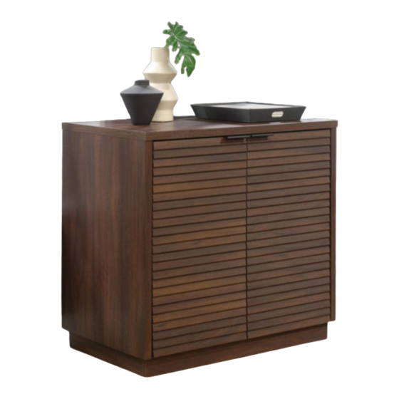
- Page 1 It stands. You sleep. Storage Cabinet NOTE: THIS INSTRUCTION BOOKLET CONTAINS IMPORTANT SAFETY INFORMATION. Elstree | Model 5426909 PLEASE READ AND KEEP FOR FUTURE REFERENCE.
- Page 2 Table of Contents Assembly Tools Required Part Identification No. 2 Phillips Screwdriver Tip Shown Actual Size Hardware Identification Assembly Steps 5-21 Français 22-25 Tape Measure Español 26-29 Safety Warranty Page 2...
- Page 3 Now you know Part Identification our ABCs. å While not all parts are labeled, some of the parts will have a label or an inked letter on the edge to help distinguish similar parts from each other. Use this part identification to help identify similar parts. RIGHT END (1) LARGE BASE (2) RIGHT DOOR (1)
-
Page 4: Table Of Contents
Hardware Identification å Screws are shown actual size. You may receive extra hardware with your unit. HIDDEN CAM - 4 CAM DOWEL - 4 WOOD DOWEL -4 36F TWIST-LOCK FASTENER - 4 ® 31G CORNER BRACKET - 4 14H HINGE - 4 BACK CONNECTOR - 8 METAL BRACKET - 6 189K... -
Page 5: Hidden Cam
Hardware Usage Guide HOW TO USE A TWIST-LOCK FASTENER ® Push a TWIST-LOCK® FASTENER 1. Insert the dowel end of the FASTENER into the into the large hole in the part. hole of the adjoining part. NOTE: The dowel end of the FASTENER must remain fully inserted in the hole of the adjoining part while locking the FASTENER. - Page 6 Step 1 å Assemble your unit on a carpeted floor or on the empty carton to avoid scratching your unit or the floor. å Push four TWIST-LOCK FASTENERS (36F) into the large holes in the ENDS (A and B). å Insert four WOOD DOWELS (15F) into the ENDS (A and B) using the exact holes shown.
- Page 7 Step 2 å Push four HIDDEN CAMS (1F) into the BOTTOM (C). Then, insert the metal end of a CAM DOWEL (2F) into each HIDDEN CAM. Arrow Do not tighten the HIDDEN CAMS in this step. Metal end Arrow Metal end Page 7...
- Page 8 Step 3 å Fasten the BOTTOM (C) to the LEFT END (B). Tighten two Caution HIDDEN CAMS. Do not stand the unit upright without the BACK fastened. The unit may collapse. i t h ® f a c S u r - L O I S T E R S...
- Page 9 Step 4 å Fasten the RIGHT END (A) to the BOTTOM (C). Tighten two HIDDEN CAMS. S u r f a c H I D i t h D E N i t h o ® f a c S u r - L O I S T E R S...
- Page 10 Step 5 å Carefully stand unit upright. å Slide the BACK (G) into the grooves in the ENDS (A and B) and the BOTTOM (C). If fastening a Hutch to this unit, the unit MUST be placed against a wall. F i n i s h e p l a...
- Page 11 Step 6 å Fasten the TOP (K) to the ENDS (A and B). Tighten four TWIST-LOCK FASTENERS. å NOTE: Be sure the BACK (G) inserts into the groove in Meet Part (K). This component has been engineered to be lighter, stronger, the TOP (K).
- Page 12 Step 7 å If you are not placing this unit against a wall, skip this step and go straight to Step 8. å Carefully turn your unit onto its front edges. Use two BACK CONNECTORS per side. 2-3" in from each corner. å...
- Page 13 Step 8 å Carefully turn your unit onto its back edges. å Fasten eight BACK CONNECTORS (39F) to the ENDS (A and B), BOTTOM (C), TOP (K), and BACK (G). Tighten the SCREW in each BACK CONNECTOR. 2" 3" Use two BACK CONNECTORS per side.
-
Page 14: Black 9/16" Large Head Screw
Step 9 å Carefully set your unit on its top. å Fasten four CORNER BRACKETS (31G) to the BOTTOM (C) exactly as shown. Use eight BLACK 9/16" LARGE HEAD SCREWS (1S). BLACK 9/16" LARGE HEAD SCREW (8 used in this step) Page 14... - Page 15 Step 10 å Fasten six METAL BRACKETS (4G) to the LARGE BASES (E) and SMALL BASES (F). Use six BLACK 9/16" LARGE HEAD SCREWS (1S). å NOTE: Be sure the BRACKETS are even with the edges of the LARGE BASES and SMALL BASES. BLACK 9/16"...
- Page 16 Step 11 å Fasten the SMALL BASES (F) to the BOTTOM (C). Use two BLACK 9/16" LARGE HEAD SCREWS (1S) through the METAL BRACKETS on the SMALL BASES and into the BOTTOM. å Fasten the SMALL BASES (F) to the CORNER BRACKETS.
- Page 17 Step Step 12 å Fasten the LARGE BASES (E) to the BOTTOM (C). Use four BLACK 9/16" LARGE HEAD SCREWS (1S) through the METAL BRACKETS on the SMALL BASES and into the BOTTOM. å Fasten the LARGE BASES (E) to the CORNER BRACKETS.
-
Page 18: Black 1/2" Flat Head Screw
Step Step 13 å Fasten two HINGES (14H) to each of the DOORS (H and J). Use eight BLACK 1/2" FLAT HEAD SCREWS (11S). BLACK 1/2" FLAT HEAD SCREW (8 used in this step) Page 18... -
Page 19: Hinge
Step Step 14 å Carefully stand your unit upright. å Push the RUBBER SLEEVES (2R) over the METAL PINS (1R). Insert the METAL PINS (1R) into the hole locations of your choice in the ENDS (A and B). Set the ADJUSTABLE Stop SHELF (D) onto the METAL PINS. - Page 20 Step Step 15 å Refer to the enlarged diagram to identify the parts on Mounting screw (depth) the HINGES. Adjusting screw (horizontal) å The DOORS may need some adjustments. Follow the text below to make needed adjustments. å DOOR ADJUSTMENTS: To adjust the DOORS from side to side (horizontal), turn the adjusting screw in or out.
- Page 21 Step Step 16 å NOTE: Please read the back pages of the instruction booklet for important safety information. å This completes assembly. Clean with a damp cloth. Wipe dry. Page 21...
Need help?
Do you have a question about the Elstree 5426909 and is the answer not in the manual?
Questions and answers