
Subscribe to Our Youtube Channel
Related Manuals for Teknik Hampstead 5426504


Summary of Contents for Teknik Hampstead 5426504
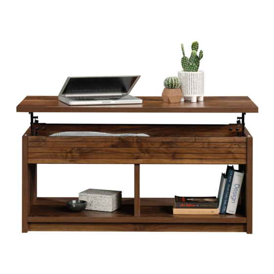
- Page 1 Teknik Guaranteed to hold other beverages, too. Hampstead Park Lift Up Table Model 5426504...
- Page 2 Table of Contents Assembly Tools Required Part Identification No. 2 Phillips Screwdriver Tip Shown Actual Size Hardware Identification Assembly Steps 5-19 Adjustable Wrench Tape Measure Page 2...
-
Page 3: Part Identification
Now you know Part Identification our ABCs. å While not all parts are labeled, some of the parts will have a label or an inked letter on the edge to help distinguish similar parts from each other. Use this part identification to help identify similar parts. RIGHT END (1) LOUVERED PANEL (2) BASE (2) -
Page 4: Hardware Identification
Hardware Identification å Screws are shown actual size. You may receive extra hardware with your unit. HIDDEN CAM - 18 CAM DOWEL - 12 CAM SCREW - 6 WOOD DOWEL - 4 METAL BLACK WASHER - 8 SUPPORT BRACKET - 2 BUMPER - 4 BRACKET - 10 74M LIFT TABLE... - Page 5 Hardware Usage Guide HOW TO USE A HIDDEN CAM & CAM DOWEL Insert the metal end of the CAM DOWEL into the HIDDEN CAM. Cam Dowel Arrow Hole Push a HIDDEN CAM into Metal end the part. The arrow in the HIDDEN CAM must point toward the hole in the edge Hidden Cam...
- Page 6 Step 1 å Assemble your unit on a carpeted floor or on the empty carton to avoid scratching your unit or the floor. å Push four HIDDEN CAMS (1F) into the short edges of the SHELF (E). Then, insert the metal end of a CAM DOWEL (2F) into each HIDDEN CAM.
- Page 7 Step 2 å Push four HIDDEN CAMS (1F) into the LOUVERED PANELS (D). Then, insert the metal end of a CAM DOWEL (2F) into each HIDDEN CAM. å Turn six CAM SCREWS (8F) into the LOUVERED PANELS (D). å Fasten the LOUVERED PANELS (D) to the SHELF (E). Tighten six HIDDEN CAMS. Metal end Arrow Arrow...
- Page 8 Step 3 å Fasten the UPRIGHT (F) to the SHELF (E). Use two BLACK 1-15/16" FLAT HEAD SCREWS (113S). 113S BLACK 1-15/16" FLAT HEAD SCREW (2 used in this step) S u r f a c H I D D E N i t h Page 8...
-
Page 9: Hidden Cam
Step 4 å Push four HIDDEN CAMS (1F) into the BOTTOM (J). Then, insert the metal end of a CAM DOWEL (2F) into each HIDDEN CAM. Meet Part (J). This component has Metal end been engineered to be lighter, stronger, faster…... - Page 10 Step 5 å Fasten ten METAL BRACKETS (4G) to the BASES (G). Use ten BLACK 9/16" LARGE HEAD SCREWS (1S). å NOTE: Be sure the BRACKETS are even with the edges of the BASES. å Fasten the BASES (G) to the BOTTOM (J). Use six BLACK 9/16" LARGE HEAD SCREWS (1S). (10 used) BLACK 9/16"...
- Page 11 Step 6 å Fasten the BOTTOM (J) to the UPRIGHT (F). Use two BLACK 1-15/16" FLAT HEAD SCREWS (113S). S u r f a c H I D D E N i t h 113S BLACK 1-15/16" FLAT HEAD SCREW (2 used in this step) Page 11...
- Page 12 Step 7 å Insert four WOOD DOWELS (15F) into the short edges of the LOUVERED PANELS (D). å Fasten the ENDS (A and B) to the LOUVERED PANELS (D), SHELF (E), and BOTTOM (J). Tighten twelve HIDDEN CAMS. å NOTE: Be sure the WOOD DOWELS in the LOUVERED PANELS insert into the ENDS.
- Page 13 Step 8 å Carefully stand your unit upright. å Push four BUMPERS (2M) into the top edges of the ENDS (A and B). Page 13...
- Page 14 Step 9 å Fasten the front edge of the LIFT TABLE MECHANISM (74M) to the TOP (H) as shown. Use two BLACK 9/16" LARGE HEAD SCREWS (1S). å IMPORTANT: You will need a tape measure to be sure the holes in the TOP (H) are the correct distance from the long edges as shown.
- Page 15 Step 10 å Fasten the SUPPORT BRACKETS (37G) to the LIFT TABLE MECHANISMS (74M). Use four BLACK WASHERS (13M), four NUTS (24M), and four BLACK 3/4" MACHINE SCREWS (92S). å NOTE: Position the SUPPORT BRACKETS exactly as shown. BLACK 3/4" MACHINE SCREW (4 used in this step) Page 15...
- Page 16 Step 11 å IMPORTANT: You will need someone's help in this step. å Fasten the LIFT TOP MECHANISMS (74M) to the ENDS (A and B). Use ten BLACK 9/16" LARGE HEAD SCREWS (1S) through the LIFT TABLE MECHANISMS (74M) and into the BLACK 9/16"...
- Page 17 Step 12 å Fasten the BUSHINGS (91M) to the ENDS (A and B). Use two BLACK 3/4" PAN HEAD SCREWS (85S) through the BUSHINGS, through two SILVER WASHERS (80M), through the LIFT TABLE MECHANISMS (74M), and into the ENDS. å NOTE: Do not overtighten the SCREWS.
- Page 18 Step 13 å Fasten the STRETCHER (C) to the SUPPORT BRACKETS (37G) on the LIFT TABLE MECHANISMS (74M). Use four BLACK WASHERS (13M), four NUTS (24M), and four BLACK 1-1/4" MACHINE SCREWS (93S). å NOTE: Use an Adjustable Wrench and a Phillips Screwdriver in this step.
- Page 19 Step 14 å IMPORTANT: Do not place valuables in the storage space. å NOTE: Please read the back pages of the instruction booklet for important safety information. å This completes assembly. Clean with a damp cloth. Wipe dry. Page 19...
- Page 20 WARNING Please use your furniture correctly and safely. Improper use can cause safety hazards, or damage to your furniture or household items. Carefully read the following chart. Look out for: What can happen: How to avoid the problem: • Overloaded shelves. •...
Need help?
Do you have a question about the Hampstead 5426504 and is the answer not in the manual?
Questions and answers