
Related Manuals for Teknik Elstree 5426908


Summary of Contents for Teknik Elstree 5426908
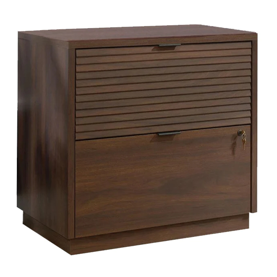
- Page 1 Teknik www.teknikoffice.co.uk Congratulations. You are now an adult. Elstree 2 Drawer Lateral Filer Model 5426908...
- Page 2 Table of Contents Assembly Tools Required Part Identification No. 2 Phillips Screwdriver Tip Shown Actual Size Hardware Identification Assembly Steps 6-29 Hammer Français 30-34 Not actual size Español 35-39 Safety 40-42 Adjustable Wrench Warranty Page 2...
-
Page 3: Part Identification
Now you know Part Identification our ABCs. å While not all parts are labeled, some of the parts will have a label or an inked letter on the edge to help distinguish similar parts from each other. Use this part identification to help identify similar parts. RIGHT END (1) D551 LEFT DRAWER SIDE (2) BACK (2) -
Page 4: Hardware Identification
Hardware Identification (EXTENSION SET SHOWN SEPARATED) EXTENSION RAIL - 4 EXTENSION SLIDE - 4 10A SLIDE CAM - 4 FILE GLIDE - 4 35MA 35MC SMALL FILE HIDDEN CAM - 6 FILE ROD - 4 FILE BAR - 4 BRACKET - 2 CAM DOWEL - 6 36F TWIST-LOCK WOOD DOWEL - 4... - Page 5 Hardware Identification å Screws are shown actual size. You may receive extra hardware with your unit. 3S GOLD 5/16" FLAT HEAD SCREW - 16 BLACK 9/16" LARGE HEAD SCREW - 48 BROWN 7/16" LARGE HEAD SCREW - 4 BLACK 1-1/8" PAN HEAD SCREW - 4 BLACK 1/2"...
- Page 6 Hardware Usage Guide HOW TO USE A TWIST-LOCK FASTENER ® Push a TWIST-LOCK® FASTENER 1. Insert the dowel end of the FASTENER into the into the large hole in the part. hole of the adjoining part. NOTE: The dowel end of the FASTENER must remain fully inserted in the hole of the adjoining part while locking the FASTENER.
- Page 7 Step 1 å Assemble your unit on a carpeted floor or on the empty carton to avoid scratching your unit or the floor. Some assembly å To begin assembly, push four SAUDER TWIST-LOCK® (and snacks) required. FASTENERS (36F) into the large holes in the ENDS (A and B). Do not tighten the TWIST-LOCK®...
- Page 8 Step 2 å Separate the EXTENSION SLIDES (35MC) from the EXTENSION RAILS (35MA) as shown in the upper diagram below. Be prepared, the parts are greasy. å Fasten the EXTENSION RAILS (35MA) to the ENDS (A and B). Use eight GOLD 5/16" FLAT HEAD SCREWS (3S) through holes #1 and #3.
- Page 9 Step 3 å Fasten the INTERLOCK MECHANISM (34G) to the RIGHT END (A). Use three BLACK 9/16" PAN HEAD SCREWS (51S). å Fasten the L - LOCK BRACKET (76G) to the RIGHT END (A). Use two BLACK 9/16" LARGE HEAD SCREWS (1S). BLACK 9/16"...
- Page 10 Step 4 å To begin assembly, push eight SAUDER TWIST-LOCK® FASTENERS (36F) into the large holes in the BACKS (G). Do not tighten the TWIST-LOCK® FASTENERS in this step. Page 10...
- Page 11 Step 5 å Fasten the RIGHT END (A) to the BACKS (G). Tighten four TWIST-LOCK® FASTENERS. Open end Unfinished edge Unfinished edge Page 11...
-
Page 12: Hidden Cam
Step 6 å Push four HIDDEN CAMS (1F) into the BOTTOM (D). Then, insert the metal end of a CAM DOWEL (2F) into each HIDDEN CAM. Arrow Metal end Do not tighten the HIDDEN CAMS in this step. Arrow Metal end Page 12... - Page 13 Step 7 å Fasten the BOTTOM (D) to the RIGHT END (A). Tighten two HIDDEN CAMS. D E N H I D i t h f a c S u r These edges must be even. Page 13...
- Page 14 Step 8 å Fasten the LEFT END (B) to the BOTTOM (D) and BACKS (G). Tighten two HIDDEN CAMS and tighten four TWIST-LOCK® FASTENERS. Open end Page 14...
- Page 15 Step 9 å Insert four WOOD DOWELS (15F) into the ENDS (A and B). å Fasten the TOP (C) to the ENDS (A and B). Tighten four TWIST-LOCK® FASTENERS. å NOTE: Be sure the WOOD DOWELS in the ENDS insert into the TOP.
- Page 16 Step 10 å Carefully turn your unit onto its top. å Fasten the CORNER BRACKETS (31G) to the BOTTOM (D). Use eight BLACK 9/16" LARGE HEAD SCREWS (1S). BLACK 9/16" LARGE HEAD SCREW (8 used in this step) Page 16...
- Page 17 Step 11 å Fasten six METAL BRACKETS (4G) to the BASES (E and F). Use six BLACK 9/16" LARGE HEAD SCREWS (1S). å NOTE: Be sure the BRACKETS are even with the edges of the BASES. BLACK 9/16" LARGE HEAD SCREW (6 used in this step) Page 17...
- Page 18 Step 12 å Fasten SMALL BASES (F) to the BOTTOM (D). Use eight BLACK 9/16" LARGE HEAD SCREWS (1S) through the CORNER BRACKETS on the BOTTOM and into the holes in the SMALL BASES. å Fasten the BOTTOM (D) to the METAL BRACKETS on the SMALL BASES (F).
- Page 19 Step 13 å Fasten LARGE BASES (E) to the BOTTOM (D). Use eight BLACK 9/16" LARGE HEAD SCREWS (1S) through the Now might be a CORNER BRACKETS on the BOTTOM and into the holes good time to refresh in the LARGE BASES. your drink.
- Page 20 Step 14 å Fasten the BALLAST (J) to the BOTTOM (D). Use four BLACK 1-1/8" PAN HEAD SCREWS (9S). BLACK 1-1/8" PAN HEAD SCREW (4 used in this step) Page 20...
- Page 21 Step 15 å Fasten the Z - LOCK BRACKET (77G) to the SMALL DRAWER FRONT (K). Use two BLACK 9/16" LARGE HEAD SCREWS (1S). BLACK 9/16" LARGE HEAD SCREW (2 used in this step) Page 21...
- Page 22 Step 16 The tabs should insert freely With the palm of your hand, into the slots. Gently tilt the tap the DRAWER BOTTOM DRAWER SIDES side to side down into the groove. until the tabs slip into the slots. U n fi n i s h s u r f a c...
- Page 23 Step 17 å Fasten a LARGE FILE BRACKET (57G) to the SMALL DRAWER FRONT (K). Use two BLACK 9/16" LARGE HEAD SCREWS (1S). å Fasten the SMALL FILE BRACKET (11B) to the DRAWER BACK (D552). Use two BROWN 7/16" LARGE HEAD SCREWS (6S).
- Page 24 Step 18 å Insert a SLIDE CAM (10A) into the DRAWER SIDES (D550 and D551). å Fasten the EXTENSION SLIDES (35MC) to the DRAWER SIDES (D550 and D551). Use four GOLD 5/16" FLAT HEAD SCREWS (3S) through holes #1 and #3. å...
- Page 25 Step 19 å Fasten the DRAWER ACTUATORS (62G) to the RIGHT DRAWER SIDES (D550) as shown. Use six BLACK 1/2" FLAT HEAD SCREWS (11S). å Fasten the PULLS (189K) to the DRAWER FRONTS (H and K). Use four BLACK 9/16" LARGE HEAD SCREWS (1S). BLACK 9/16"...
- Page 26 Step 20 å Press one of the FILE GLIDES (4B) over the RIGHT DRAWER SIDE (D550) on the drawer. The FILE GLIDES are necessary to hang files. å Slide the FILE RODS (9B) through a FILE BAR (14B) and into the holes shown in the SMALL FILE BRACKET (11B) and LARGE FILE BRACKETS (57G), other FILE BAR (14B) and FILE GLIDE (6B) on the RIGHT DRAWER SIDE (D550).
- Page 27 Step 21 å Fasten the LOCK PACK (21J) to the LARGE DRAWER FRONT (H) in the exact order shown. It is If you're doing this to important to be sure the CAM points as shown. help a friend, don't leave without a bite. å...
- Page 28 Step 22 å Carefully stand your unit upright. å Pull the lower wing of the INTERLOCK MECHANISM (34G) forward until it clicks into place as shown in diagram 1. å To insert the lower drawer into your unit, line up the EXTENSION SLIDES on the drawers with the EXTENSION RAILS on the unit and push the drawer into the unit until the drawer it is fully inserted.
- Page 29 Step 23 å To make adjustments to the drawer, loosen SCREW #3 in the SLIDES a 1/4 turn, then turn the cam clockwise or counter- clockwise. Notice how the drawer raises or lowers as you turn the cam. By adjusting the drawer this way, it will help the DRAWER FRONT line up better when closed.
- Page 30 CAUTION Please use your furniture correctly and safely. Improper use can cause safety hazards, or damage to your furniture or household items. Carefully read the following chart. Look out for: What can happen: How to avoid the problem: • Overloaded file cabinet drawers. •...
Need help?
Do you have a question about the Elstree 5426908 and is the answer not in the manual?
Questions and answers